
Related Manuals for Jafar 2312


Summary of Contents for Jafar 2312
- Page 1 OPERATING MANUAL Flanged gate valves with soft seals P/N 2312, 2314, OPERATING MANUAL 11-2020...
- Page 2 TABLE OF CONTENTS INTENDED USE ............................3 TECHNICAL DESCRIPTION ........................3 PRODUCT IDENTIFICATION MARKING .................... 4 STORAGE & TRANSPORT ........................6 INSTALLATION ............................6 OPERATION AND MAINTENANCE ....................... 6 SAFETY ................................ 8 WARRANTY ..............................8 OPERATING MANUAL 11-2020...
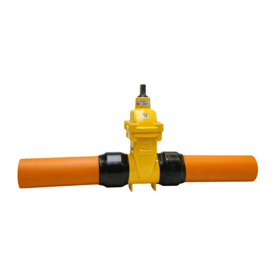
- Page 3 T-socket wrench. The valve body 2312 features bell socket ends with transverse grooves cut along the outer surface on which PE pipe ends are slid over. The pipes at the grooved bell socket length are press fit with pressed steel rings that provide sure and tight joint.
- Page 4 3. PRODUCT IDENTIFICATION MARKING The gate valve marking meets the following standards: EN 19 (Industrial valves. Marking metal fittings), Marking of metallic valves), EN 1074-1 (Valves for water supply. Fitness for purpose requirements and appropriate verification tests. Part 1: General requirements). The gate valve bodies feature markings on the front and back walls of the body chamber.
- Page 5 The location on the valve specified in the documentation features the nameplate which contains the following data: Manufacturer's company and country of origin Manufacturer's company logo Polish construction mark (for the full range of diameter values) Alphanumerical reference designation for the bolt hole pattern drilling on the flange to be connected to the piping (PN) CE marking Maximum permitted pressure (PS) Maximum / minimum permissible temperature (TS)
- Page 6 The Type 2312 gas gate valves are intended for installation between resistance-welded pipeline ends. The Type 2314 gas gate valves are intended for installation between fusion-welded pipeline ends.
- Page 7 If all the actions above have been completed with a good result, visually inspect the corrosion protection. If the paint coat is damaged, rebuild it with the paint kits available from JAFAR. Replacing the seal in the cover: Fully open the valve (until you clearly sense that the wedge closure (7) resists further movement; this will seal the spindle under the flange (6)).
- Page 8 Operating Manual may cause death, severe bodily injury or substantial property damage. Fabryka Armatur Jafar S.A. shall not be liable for any accidents or emergencies related to incorrect installation or operation of the product. Note that the valve installation could be pressurized or contain various type of stray gas or aggressive liquids.
Need help?
Do you have a question about the 2312 and is the answer not in the manual?
Questions and answers