Table of Contents
Advertisement
Quick Links
Approved for use by
Failure to comply with the guidelines and instructions in this Operation and
Maintenance Manual releases the manufacturer from all obligations, liability and guarantee.
Due to continuous business development, we reserve the right to introduce
modifications and structural changes to the presented product.
Operation and maintenance
manual for
FLANGED
GATE VALVES
WITH SOFT SEALS
P/N
2112
President of Factory, JAFAR S.A.
OPERATION AND MAINTENANCE MANUAL
12-2016
Advertisement
Table of Contents

Related Manuals for Jafar 2112


Summary of Contents for Jafar 2112
- Page 1 WITH SOFT SEALS 2112 Approved for use by President of Factory, JAFAR S.A. Failure to comply with the guidelines and instructions in this Operation and Maintenance Manual releases the manufacturer from all obligations, liability and guarantee. Due to continuous business development, we reserve the right to introduce modifications and structural changes to the presented product.
-
Page 2: Table Of Contents
CONTENTS 1 TECHNICAL DESCRIPTION ........................... 3 1.1 PRODUCT DESIGNATION AND IDENTIFICATION ................3 1.2 USE ................................3 1.3 TECHNICAL SPECIFICATION ........................3 2 DESIGN ................................3 2.1 DESCRIPTION OF THE VALVE DESIGN ....................3 2.2 MATERIALS ..............................4 2.3 DIMENSIONS .............................. 5 2.4 REFERENCE STANDARDS ........................ -
Page 3: Technical Description
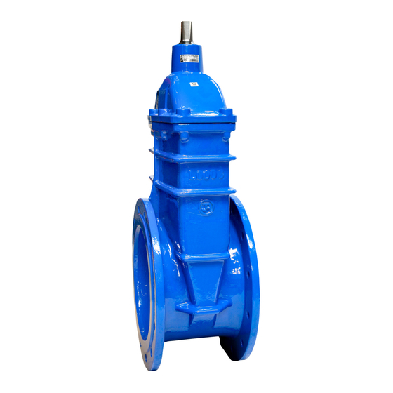
2.1 DESCRIPTION OF THE VALVE DESIGN Type 2112 gate valves with soft seals manufactured by F.A. „JAFAR”S.A. feature a smooth walled bore, a non-ring spindle, and an o-ring spindle seal installed in a head-type valve cover. The stem is guided by a bushing in the valve cover neck and a sealing plug. -
Page 4: Materials
cap screws mounted flush with the valve cover and preserved with a paraffin compound. The valve cover to body seal is a rubber gasket which also seals the bolt penetration points to prevent any leaks from their leads. All inner and outer cast-iron surfaces of the valve are epoxy powder coated. -
Page 5: Dimensions
2.3 DIMENSIONS No. of turns for Mass PN16 (PN10) PN16 (PN10) PN16 (PN10) opening [mm] [mm] [kg] 13,5 10,5 15,0 19,5 26,0 33,5 48,2 12 (8) 34,5 73,3 355 (350) 28 (23) 42,5 97,0 410 (400) 28 (23) 134,5 OPERATION AND MAINTENANCE MANUAL 12-2016... -
Page 6: Reference Standards
2.4 REFERENCE STANDARDS EN 1074-1 Valves for water supply. Fitness for purpose requirements and appropriate verification tests. General requirements EN 1074-2 Valves for water supply. Fitness for purpose requirements and appropriate verification tests. Isolating valves. 89/H-02650 Valves and pipelines. Pressure and temperature ratings. EN 1092-2 Flanges and their joints. -
Page 7: Production And Acceptance
2.6 PRODUCTION AND ACCEPTANCE Type 2112 gate valves are accepted and produced in accordance with EN 1074-2 (Valves for water supply. Fitness for purpose requirements and appropriate verification tests. Isolating valves) and EN 12266-1 (Industrial valves. Testing of valves). All valves (100%) are subject to tightness testing. -
Page 8: Transport
4 ASSEMBLY AND INSTALLATION 4.1 ASSEMBLY GUIDELINES The Type 2112 flanged cast iron gate valves can be installed in underground or overground pipelines both in horizontal or vertical orientation. The listed products are suitable for joining with the flanged ends of pipelines with the size equal to that of the valve flanges. -
Page 9: Assembly Instructions
4.2 ASSEMBLY INSTRUCTIONS Before attempting to install the valve, check the technical and commercial documents delivered with the product to verify that the media and pipeline operating parameters comply with the manufacturer's declaration. Any change in the operating conditions must be consulted with the valve manufacturer beforehand. Before attempting to assemble the valve, remove the main bore plugs, check the inner surfaces of the valve and thoroughly flush with water, if necessary.
Need help?
Do you have a question about the 2112 and is the answer not in the manual?
Questions and answers