Table of Contents
Advertisement
Quick Links
Approved for use by
Failure to comply with the guidelines and instructions in this Operation and
Maintenance Manual releases the manufacturer from all obligations, liability and guarantee.
Due to continuous business development, we reserve the right to introduce
modifications and design changes to the presented product.
OPERATION AND MAINTENANCE MANUAL
Operation and maintenance
manual for
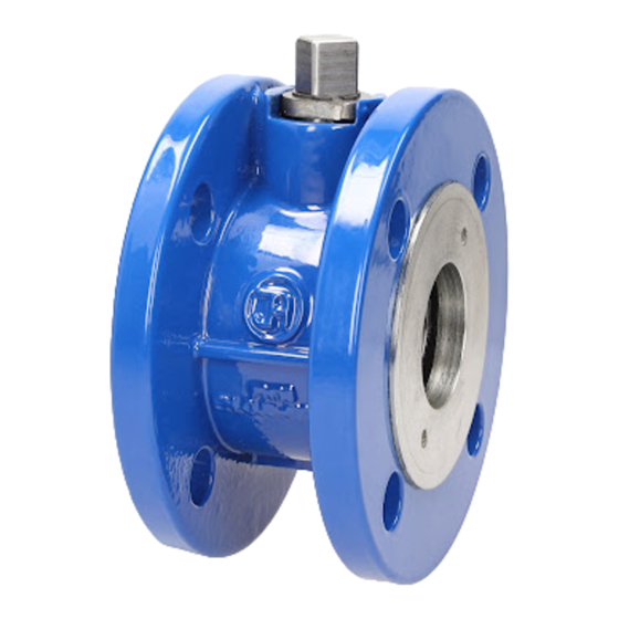
BALL
VALVES
P/N
5220
5320
5321
President of Factory, JAFAR S.A.
01-2016
1
Advertisement
Table of Contents

Summary of Contents for Jafar 5220
- Page 1 5320 5321 Approved for use by President of Factory, JAFAR S.A. Failure to comply with the guidelines and instructions in this Operation and Maintenance Manual releases the manufacturer from all obligations, liability and guarantee. Due to continuous business development, we reserve the right to introduce modifications and design changes to the presented product.
-
Page 2: Table Of Contents
CONTENTS 1 TECHNICAL DESCRIPTION ........................... 3 1.1 PRODUCT DESIGNATION AND IDENTIFICATION ................3 1.2 USE ................................3 1.3 TECHNICAL SPECIFICATION ........................3 2 DESIGN ................................5 2.1 DESCRIPTION OF THE VALVE DESIGN ....................5 2.2 MATERIALS ..............................5 2.3 DIMENSIONS .............................. 7 2.4 REFERENCE STANDARDS ........................ -
Page 3: Technical Description
- optional drive actuator ready 1.2 USE The TYPE 5220 & 5320 flanged and TYPE 5321 welded ends ball valves are intended for isolation of medium flow in industrial systems, heating systems and other systems. (Group 2 fluids, ref. Directive 97/23/EC). The valves can be operated both in underground and overground installations as installed in vertical or horizontal pipelines. - Page 4 - TYPE 5220 with flanged ends, diameter range: DN40-125[mm] - 16/25/40PN; - TYPE 5220, cast iron, with flanged ends, diameter range: DN4-125[mm] - 16PN; - TYPE 5320 with flanged ends, diameter range: DN15-50[mm] - 16/25/40PN; DN50-300[mm] - 16/25PN; - TYPE 5321 with welded ends, diameter range: DN15-50[mm] - 16/25/40PN;...
-
Page 5: Design
2.1 DESCRIPTION OF THE VALVE DESIGN F.A. JAFAR S.A manufactures the TYPE 5220, 5320 & 5321 water ball valves, with the TYPE 5220 full bore valves and the TYPE 5320 & 5321 reduced bore valves. The valve body is a welded structure with a free-floating ball up to DN200 (larger sizes have trunnion balls), an internal compensation system, and a closure seal in the form of a ball set in a seat, made by two seals. - Page 6 TYPE 5320 Item Part designation Material Reference standard Body Steel grade 1.0425 PN-EN 10028-2:2010 Spring Steel grade 1.8159 PN-EN 10270-3:2011 Steel grade 1.4541 Ball PN-EN 10088-1: 2014 Steel grade 1.4301 Ball seal PTFE+C PN-EN ISO 13000-1:2007 Seal mount Steel grade 1.0425 PN-EN 10028-2: 2010 Steel, Fe/Zn5 PN-EN ISO 4032:2013...
-
Page 7: Dimensions
2.3 DIMENSIONS - TYPE 5220 (flanged ball valve) TYPE 5220 table OPERATION AND MAINTENANCE MANUAL 01-2016... - Page 8 Weight m3/h Steel 4x18 4x18 16/25/40 8x18 8x18 25/40 8xM20 16,6 25/40 8xM24 1023 23,5 Cast iron 4x19 4x19 8x19 8x19 11,2 8xM16 17,3 8xM16 1023 24,5 - TYPE 5320 (reduced bore flanged ball valve) TYPE 5320 table OPERATION AND MAINTENANCE MANUAL 01-2016...
- Page 9 Weight [mm] [bar] [mm] [pcs.] [mm] [kg] 16 / 25 / 40 16 / 25 / 40 16 / 25 / 40 16 / 25 / 40 16 / 25 / 40 16 / 25 / 40 8 (4) 11,0 11,6 13,2 14,7...
-
Page 10: Reference Standards
Weight [mm] [bar] [mm] [kg] 21,3 50,7 26,9 53,5 33,7 56,9 42,4 60,2 48,3 83,2 60,3 89,2 76,1 109,1 88,9 121,5 114,3 149,2 139,7 164,9 14,5 168,3 187,2 1070 23,5 219,1 224,5 1420 56,0 273,1 267,5 2620 100,0 323,9 5820 152,0 2.4 REFERENCE STANDARDS PN-EN 1074-2:2003... -
Page 11: Production And Acceptance
3 PROTECTION, STORAGE & TRANSPORT 3.1 PROTECTIVE COATINGS All outer surfaces of the valve body, except for the interface surfaces of TYPE 5220 & 5320 flanged valves and TYPE 5320 valve welded end surfaces are preserved with a RAL 1023 coat. -
Page 12: Assembly And Installation
The ball valves: - with flanged ends (TYPE 5220 & 5320), adapted for flanged connection with the pipeline ends that meet the valve flange dimensions per PN-EN 1092-1:2013 and PN-EN 1092-2:1999; - with welded ends (TYPE 5321), adapted for welded connection with the pipeline ends that meet the valve welded end dimensions per PN-EN 12627:2002. - Page 13 down, bolt the ball valve between the pipe end flanges. Add more gaskets if the flange to flange gap is too wide. Pressure test and strength test the pipeline with the valve fully open. Caution! If the product has mechanical damage, do not install it in the pipeline. The assembly method is shown in the following figure: OPERATION AND MAINTENANCE MANUAL 01-2016...
- Page 14 TYPE 5220 (DN40/50/65/80) 1. Ball valve; 2. Gasket; 3. Pipeline flange; 4. Washer; 5. Fastening bolt; 6. Nut. TYPE 5220 (DN100/125) 1. Ball valve; 2. Gasket; 3. Pipeline flange; 4. Washer; 5. Fastening bolt. TYPE 5320 1. Ball gate; 2. Pipeline flange; 3. Fastening bolt; 4. Washer; 5. Nut; 6. Seal.
-
Page 15: Operation
TYPE 5321 1. Valve; 2. Steel pipeline; 3. Joint. Caution! If the product has mechanical damage, do not install it in the pipeline. Caution! Keep the cut-off valve closed during the system pressure test. 4.3 OPERATION The ball valve shall be operated according to all relevant requirements for cut-off valves, i.e. either in fully open or fully closed positions.


Need help?
Do you have a question about the 5220 and is the answer not in the manual?
Questions and answers