Table of Contents
Advertisement
Quick Links
Approved for use by
Failure to comply with the guidelines and instructions in this Operation and
Maintenance Manual releases the manufacturer from all obligations, liability and guarantee.
Due to continuous business development, we reserve the right to introduce
modifications and structural changes to the presented product.
Operation and maintenance
manual for
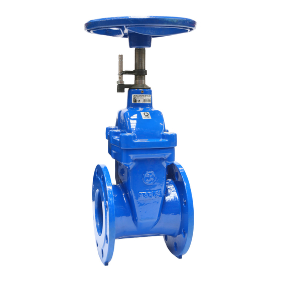
GATE VALVES
WITH SOFT SEALS
AND OPENING INDICATOR
P/N
2502; 2511
President of Factory, JAFAR S.A.
OPERATION AND MAINTENANCE MANUAL
12-2016
Advertisement
Table of Contents


Need help?
Do you have a question about the 2502 and is the answer not in the manual?
Questions and answers