Table of Contents
Advertisement
Quick Links
Approved for use by
Failure to comply with the guidelines and instructions in this Operation and
Maintenance Manual releases the manufacturer from all obligations, liability and warranty.
Due to the continuous development of the company, we reserve the right to
modifications and design changes in the product presented herein.
Operation
and Maintenance Manual
CHECK
BALL
VALVES
P/N
6516
President of Factory, JAFAR S.A.
OPERATION AND MAINTENANCE MANUAL
09-2015
Advertisement
Table of Contents

Related Manuals for Jafar 6516


Summary of Contents for Jafar 6516
- Page 1 VALVES 6516 Approved for use by President of Factory, JAFAR S.A. Failure to comply with the guidelines and instructions in this Operation and Maintenance Manual releases the manufacturer from all obligations, liability and warranty. Due to the continuous development of the company, we reserve the right to modifications and design changes in the product presented herein.
-
Page 2: Table Of Contents
CONTENTS 1 TECHNICAL DESCRIPTION ..........................3 1.1 PRODUCT DESIGNATION AND IDENTIFICATION ................3 1.2 USE ................................3 1.3 TECHNICAL CHARACTERISTICS ......................3 2 DESIGN ................................3 2.1 DESCRIPTION OF THE VALVE DESIGN ....................3 2.2 MATERIALS ..............................4 2.3 DIMENSIONS .............................. 5 2.4 REFERENCE STANDARDS ........................ -
Page 3: Technical Description
0.03 0.04 0.05 The Type 6516 valve connection flange design is acc. to PN-EN 1092-2: 1999 with the sizes compliant with the nominal pressure values. Installation length of (Type 6516) flange valves is acc. to PN-EN 558+A1: 2012, series 48. -
Page 4: Materials
2.2 MATERIALS The table below lists the structural materials of the check ball valves. Part designation Material Reference standard Spheroidal cast iron Body PN-EN 1563: 2012 EN-GJS-400-15 Spheroidal cast iron Cover PN-EN 1563: 2012 EN-GJS-400-15 PN-EN 1563: 2012 Cast iron or aluminium alloy Rubber-embedded ball PN-EN 1706: 2010 in rubber coating: NBR (or EPDM) -
Page 5: Dimensions
2.3 DIMENSIONS Series 48 Weight [mm] [mm] [bar] [kg] 1100 OPERATION AND MAINTENANCE MANUAL 09-2015... -
Page 6: Reference Standards
2.4 REFERENCE STANDARDS PN-EN 1074-1: 2002 Valves for water supply. Fitness for purpose requirements and appropriate verification tests. General requirements PN-EN 1074-3: 2002 Valves for water supply. Fitness for purpose requirements and appropriate verification tests. Check valves. PN-89/H-02650 Valves and pipelines. Pressure and temperature ratings. PN-EN 1092-2: 1999 Flanges and their joints. -
Page 7: Protection, Storage & Transport
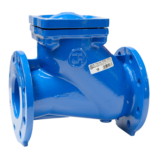
The valve bodies feature markings on the front and back walls of the body chamber. The marking contains the following data: - valve type (defined by the product reference standard number) - nominal diameter - nominal pressure - body material type - manufacturer trademark The location on the valve specified in the documentation features the nameplate which contains the following data:... -
Page 8: Assembly And Installation
4 ASSEMBLY AND INSTALLATION 4.1 ASSEMBLY GUIDELINES The Type 6516 check ball valves can be installed in underground or overground pipelines both in horizontal or vertical orientation as shown in the following figure. The flanged valves are suitable for joining with the flanged ends of pipelines with the size equal to that of the valve flanges. -
Page 9: Occupational Health And Safety
seconds. If the problem persists, stop all installation pumps, isolate the medium flow on the valve's pressure side, open the valve cover and free the ball. 4.4 OCCUPATIONAL HEALTH AND SAFETY The valves are eligible for the OHS guidelines and recommendation concerning installation of pipelines and devices for water supply stations, heat power plants, water treatment plants, sewage treatment plants, pumping stations and other facilities, and eligible for the Polish Regulation concerning general OHS laws (use of personal protective equipment for hands, legs and head, and safety garment), especially at work with low or high...
Need help?
Do you have a question about the 6516 and is the answer not in the manual?
Questions and answers