
Subscribe to Our Youtube Channel
Related Manuals for Yamaha VIKING


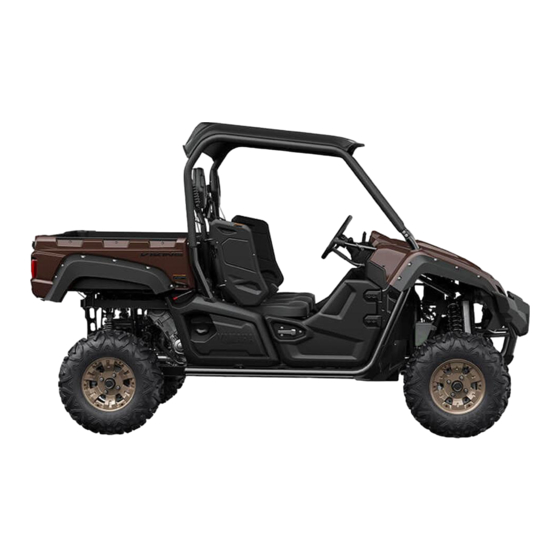
Summary of Contents for Yamaha VIKING
- Page 1 READ THIS MANUAL CAREFULLY! It contains important safety information. OWNER’S MANUAL YXM700PSE 1XP-F8199-7B...
- Page 2 Read this manual carefully before operating this vehicle. This manual should stay with this ve- hicle if it is sold. EC Declaration of Conformity conforming to Directive 2006/42/EC We, YAMAHA MOTOR CO., LTD. 2500 Shingai, Iwata, Japan, declare in sole responsibility, that the product YXM700E (YXM700PSE) (5Y4AM73W0D0500101–) (Make, model)
- Page 3 Yamaha experience in the production of fine sporting, touring, and pace-setting racing vehicles. With the purchase of this Yamaha, you can now appreciate the high degree of crafts- manship and reliability that have made Yamaha a leader in these fields.
- Page 4 EVU00021 IMPORTANT MANUAL INFORMATION FAILURE TO FOLLOW THE WARNINGS CONTAINED IN THIS MANUAL CAN RESULT IN SE- RIOUS INJURY OR DEATH. Particularly important information is distinguished in this manual by the following notations: This is the safety alert symbol. It is used to alert you to potential personal injury hazards.
- Page 5 ● It is illegal to operate this vehicle on public lands where vehicles its size are prohibited. YXM700PSE OWNER’S MANUAL ©2014 by Yamaha Motor Co., Ltd. 1st edition, January 2014 All rights reserved. Any reprinting or unauthorized use without the written permission of Yamaha Motor Co., Ltd.
-
Page 6: Table Of Contents
EVU00050 Adjusting the driver seat position...4-19 CONTENTS Seat belts ........4-20 Glove compartment .......4-21 LOCATION OF THE WARNING Storage compartments ....4-21 AND SPECIFICATION LABELS..1-1 Cup holders........4-23 Cargo bed ........4-24 SAFETY INFORMATION....1-2 The front and rear shock absorber assemblies ........4-27 DESCRIPTION ......... - Page 7 LEARNING TO OPERATE YOUR VEHICLE ........7-14 OPERATION........6-1 Personal protective equipment..7-14 Engine break-in....... 6-1 Practice for new Yamaha Viking Starting the engine......6-2 users ..........7-15 Drive select lever operation and Getting ready to ride ...... 7-16 reverse driving....... 6-4 Turning...........7-16...
- Page 8 Rough terrain......... 7-24 Cleaning the air filter case/duct Pavement ........7-24 check hose........8-29 Water ..........7-24 V-belt case drain plug ....8-30 Loose terrain/slippery terrain..7-25 Cleaning the spark arrester ...8-30 Brush or wooded areas ....7-26 Valve clearance ......8-31 Encountering obstacles....7-26 Brakes..........8-32 Checking the front and rear brake PERIODIC MAINTENANCE AND...
- Page 9 Wheel removal ......8-39 Tire replacement ......8-40 Wheel installation ......8-41 Battery ........... 8-41 Jump-starting ........ 8-45 Fuse replacement ......8-47 Replacing a headlight bulb ... 8-49 Headlight beam adjustment ..8-52 Tail/brake light bulb replacement ........ 8-53 Troubleshooting ......8-55 Troubleshooting charts ....
-
Page 10: Location Of The Warning And Specification Labels
EVU00060 L OCATION OF THE WARNING AND SPECIFICATION LABELS... - Page 11 Read and understand all of the labels on your vehicle. They contain important information for safe and proper operation of your vehicle. Never remove any labels from your vehicle. If a label becomes difficult to read or comes off, a re- placement label is available from your Yamaha dealer.
- Page 12 1 For Europe 4 For Europe AVERTISSEMENT YXM700ES 2014 35.0 kW WARNING WARNING YAMAHA MOTOR CO.,LTD. 635 kg 2500 SHINGAI,IWATA,JAPAN 1XD-F155A-10 Any part of your Any part of your Toute partie du corps body (arms, legs, body (arms, legs, (bras, jambes, tête) se...
- Page 13 7 For Europe WARNING Do not rest hands or arms on door or shoulder bolster. To avoid Injury, keep hands and arms completely Inside the vehicle by holding the steering wheel or handhold. YAMAHA 1XD-K8483-00 6 For Europe WARNING AVERTISSEMENT Ne pas appuyer les mains ni les bras sur la portiè...
- Page 14 (if applicable) du passager, des accessoires, de l’équipement, et trailer tongue weight. (le cas échéant) du timon. YAMAHA 1XD-F1696-10 YAMAHA 1XD-F1696-20...
- Page 15 A For Europe WARNING Fuel vapors can be a fire or explosion hazard. To avoid injury or death, never store fuel or flammable liquids in this storage compartment. Storage should not exceed 10 lbs (4.5 kg) 1XP-F151F-00 1HP-F2259-21 B For Europe AVERTISSEMENT Les vapeurs d’essence peuvent provoquer un icendie ou une explosion.
- Page 16 • Avoid hills and rough terrain. – Éviter les pentes et les terrains accidentés. Lire le Manuel du propriétaire avant de charger le véhicule, • Read Owner’s Manual before loading, towing, or pulling de tirer ou de remorquer une charge. objects. YAMAHA 1XD-F4897-10 YAMAHA 1XD-F4897-00...
- Page 17 • Tow or pull only from hitch bracket. Ne jamais tenter d’empê cher un capotage à l’aide • Read Owner’s Manual du bras ou de la jambe. before loading, towing, or YAMAHA 1XD-K7762-10 pulling objects. YAMAHA 1XD-F151K-00...
- Page 18 MAX 7.3 INCH capotage ou autre accident. • Attacher solidement le (185MM) chargement afin de l’immobiliser. YAMAHA 5UG-F151J-00 • Ne jamais dépasser le poids en flèche de 490 N(50 kgf)/110 lbf du dispositif d’attelage. • Ne pas remorquer une...
- Page 19 K For Europe Liste de vérification de sécurité intégrale Tête Casque et protection des yeux Corps Ceinture de sécurité et vêtements de protection Mains À l’intérieur du véhicule, tenantla poignée de maintien ou le volant. Pieds Sur le plancher ou les repose-pieds, prêts à encaisser le choc;...
- Page 20 R e ad T ip s Gu ide fo r the Recrea ti on a l Off-Hi gh way Ve hi cl e Dr i ver Fol low Al l Instr u ctio n a nd Wa r ni ng s YAMAHA 1XD-F1568-00 B e P r e p a r e d A d j u s t , l o c k a n d n eve r r e m o ve h a n d h o l d .
- Page 21 Ne jamais permettre à plus de deux occupants à prendre place dans le véhicule. Lire le Manuel du propriétaire. Lire le Guide de conseils à l’intention du conducteur du véhicule récréatif hors route. Suivre toutes les directives et tous les avertissements. YAMAHA 1XD-F1568-10 1-12...
-
Page 22: Safety Information
Viking. While understanding all parts of this manual are important for vehicle ownership, be sure to read this chapter and the instructions in Chapter 7 before operating your Yamaha Viking. Also use these two chapters and the labels on the vehicle to instruct new operators and passengers. - Page 23 Before you operate your Yamaha Viking ● Prepare yourself and your passengers: • This vehicle is intended for use only by an operator 16 or older with a valid motor vehicle li- cense. Check country laws for minimum age requirements.
- Page 24 Prepare your vehicle Perform the pre-operation checks each time you use the vehicle to make sure it is in safe operat- ing condition. Failure to inspect or maintain the vehicle properly increases the possibility of an ac- cident or equipment damage. See page 5-1 for a list of pre-operation checks. Prepare your load or trailer Carrying loads, towing a trailer, or pulling objects can affect handling, stability, and cause the risk of overturns or other accidents.
- Page 25 Abrupt maneuvers or aggressive driving, even on flat, open areas, can cause loss of control, including rollovers. The Viking has higher ground clearance and other features to handle rug- ged terrain, and, as a result, can overturn in situations where some other vehicles may not.
- Page 26 ● Avoid rollovers: • Use care when turning: • Turning the steering wheel too far or too fast can result in a rollover. • Avoid sideways sliding, skidding, or back-wheel sliding, and never do donuts. • Slow down before entering a turn and avoid hard braking in a turn. •...
- Page 27 ● If you think or feel that the vehicle may tip or roll, keep your body completely inside the protec- tive structure of the vehicle: • Brace yourself by pressing your feet firmly on the floorboards and keep a firm grip on the steering wheel or passenger handhold.
- Page 28 Avoid carbon monoxide poisoning All engine exhaust contains carbon monoxide, a deadly gas. Breathing carbon monoxide can cause headaches, dizziness, drowsiness, nausea, confusion, and eventually death. Carbon monoxide is a colorless, odorless, tasteless gas which may be present even if you do not see or smell any engine exhaust.
- Page 29 Many companies with no connection to Yamaha manufacture parts and accessories or offer other modifications for Yamaha vehicles. Yamaha is not in a position to test the products that these af- termarket companies produce. Therefore, Yamaha can neither endorse nor recommend the use of accessories not sold by Yamaha or modifications not specifically recommended by Yamaha, even if sold and installed by a Yamaha dealer.
- Page 30 Aftermarket tires and rims The tires and rims that came with your Viking were designed to match the performance capabili- ties and to provide the best combination of handling, braking, and comfort. Other tires, rims, sizes, and combinations may not be appropriate. Refer to page 8-40 for tire specifications and more in-...
-
Page 31: Description
EVU00080 D ESCRIPTION 1 2 3 I J K 1. Headlight 15. Engine oil dipstick 2. Front shock absorber assembly 16. Passenger seat belt 3. Brake fluid reservoir 17. Passenger seat 4. Driver seat 18. Air filter 5. Driver seat belt 19. - Page 32 26. Light switch 37. Multi-function meter unit 27. On-Command drive knob 38. Passenger handhold 28. Steering wheel 39. Glove compartment 29. Main switch 40. Auxiliary DC jack 30. Parking brake lever 41. Storage compartment 31. Helmet indicator light 32. Seat belt indicator light The vehicle you have purchased may differ 33.
-
Page 33: Instrument And Control Functions
EVU00130 I NSTRUMENT AND CONTROL Functions of the respective switch positions FUNCTIONS are as follows: “ ” (on): EVU00140 All electrical circuits are supplied with power. Main switch The key cannot be removed. The helmet indicator light comes on and stays on while the key is turned to “... -
Page 34: Indicator Lights And Warning Lights
EVU00150 Indicator lights and warning lights 1. Helmet indicator light “ ” 2. Seat belt indicator light “ ” 1. On-Command differential gear lock indicator light EVU01140 “DIFF. LOCK” Low-range indicator light “L” 2. Low-range indicator light “L” This indicator light comes on when the drive 3. - Page 35 EVU00170 Neutral indicator light “N” The On-Command differential gear lock indi- This indicator light comes on when the drive cator “ ” and the On-Command differential DIFF. LOCK select lever is in the “N” position. gear lock indicator light “DIFF. LOCK” come on when the On-Command drive knob “2WD/ 4WD/DIFF LOCK”...
- Page 36 “ ” (on). If the warning light does not come on initially when the key is turned to “ ” (on), or if the warning light remains on, have a Yamaha dealer check the electrical circuit.
- Page 37 Yamaha dealer check the electrical circuit. If the steering load is too heavy (i.e., exces- sive steering use when the Viking is traveling at a slow speed), the power assist is reduced to protect the EPS motor from overheating.
-
Page 38: Multi-Function Meter Unit
” (on) to remind the occupants to always wear a helmet. If the indicator light does not come on when the key is turned to “ ” (on), have a Yamaha dealer check the electrical circuit. Seat belt indicator light “ ”... - Page 39 ● an hour meter (which shows the total time Odometer and tripmeter modes the engine has been running) a voltage display (which shows the battery ● voltage) a fuel meter ● a self-diagnosis device ● 1. “SELECT” button 2. “RESET” button 3.
- Page 40 To reset a tripmeter, select it by pushing the Clock, hour meter and voltage display “SELECT” button, and then push the “RE- modes SET” button for at least three seconds. The tripmeters can be used to estimate the dis- tance that can be traveled with a full tank of fu- el.
- Page 41 To set the clock Voltage display mode 1. Set the display to the clock mode. 2. Push the “SELECT” button and “RESET” button together for at least three sec- onds. 3. When the hour digits start flashing, push the “RESET” button to set the hours. 4.
- Page 42 If the voltage display indicates “LO” or “HI”, there may be trouble with the battery charging circuit or the battery may be faulty. If this occurs, have a Yamaha dealer check or repair the vehicle. 1. Fuel level warning indicator 2.
- Page 43 If a problem is detected in an elec- trical circuit, all the display segments and fuel level warning indicator start flashing. If this oc- curs, have a Yamaha dealer check the electri- cal circuit. 1. Error code display 2.
-
Page 44: Light Switch
EVU00240 Light switch “ ” NOTICE If the multi-function display indicates an error code, the vehicle should be checked as soon as possible in order to avoid en- gine damage. 1. Light switch “ ” Set the switch to “ ”... - Page 45 EVU01183 On-Command drive knob “2WD/4WD/ NOTICE DIFF LOCK” Do not use the headlights with the engine turned off for an extended period of time. The battery may discharge to the point that the starter motor will not operate properly. If this should happen, remove the battery and recharge it.
-
Page 46: Horn Switch
● “4WD” (four-wheel drive): Power is sup- Horn switch “ ” plied to the rear and front wheels. Press the switch to sound the horn. “DIFF LOCK” (four-wheel drive with the dif- ● ferential gear locked): Power is supplied to the rear and front wheels with the differen- tial gear locked. -
Page 47: Accelerator Pedal
EVU00260 EVU00270 Accelerator pedal Brake pedal Press the accelerator pedal down to increase Press the brake pedal to slow or stop the ve- engine speed. Spring tension returns the ped- hicle. al to the rest position when released. Always check that the accelerator pedal returns nor- mally before starting the engine. -
Page 48: Parking Brake Lever
EVU00280 EVU00290 Parking brake lever Drive select lever The parking brake lever is located at the right The drive select lever is used to shift the vehi- side of the steering wheel. Setting the parking cle into the low, high, neutral, and reverse po- brake lever will help keep the vehicle from sitions. -
Page 49: Fuel Tank Cap
EVU00300 Fuel tank cap Doors To open a door, pull the latch outward. To close a door, push or pull the door inward until it is securely latched. Be sure the door is SE- CURELY LATCHED AFTER CLOSING IT. 1. Fuel tank cap To open Remove the fuel tank cap by turning it coun- terclockwise. -
Page 50: Seats
EVU00330 Seats To install a seat cushion, insert the projections To remove a seat cushion, lift the front of the on the rear of the seat cushion under the seat cushion, and then pull the cushion off. frame, and then insert the projection on the front of the cushion into the grommet while pushing the cushion downward. -
Page 51: Adjusting The Driver Seat Position
Adjusting the driver seat position 2. Remove the bolts. The driver seat can be adjusted to one of three positions to suit the driver’s preference. 1. Bolt (× 4) Adjust the driver seat position as follows. 1. Remove the driver seat cushion. (see the previous section “Seats”.) 4-19... -
Page 52: Seat Belts
EVU00340 3. Move the seat frame to the desired posi- Seat belts tion and align the bolt holes in the seat This vehicle is equipped with three-point seat frame with the bolt holes in the vehicle belts for the operator and passengers. Always frame. -
Page 53: Glove Compartment
EVU01191 Glove compartment Storage compartments The storage compartments are located under NOTICE the multi-function meter, under the right pas- To protect from damage, do not put metal senger seat, and under the driver seat. To ac- items, like tools, or sharply edged items, cess an under-seat compartment, remove the directly in the glove compartment. - Page 54 To access the storage compartment under the driver seat, remove the storage compart- ment cover by turning it counterclockwise. WARNING! Fuel vapors can be a fire or ex- plosion hazard. To avoid injury or death, never store fuel or flammable liquids in this storage compartment.
-
Page 55: Cup Holders
5B410005 Cup holders Maximum load limit: Be sure to tightly close the cap of any plastic Storage compartment under the driver bottle before placing it in a cup holder. seat: Some plastic bottles may not fit into the cup 4.5 kg (10 lb) holders depending on their size and shape. -
Page 56: Cargo Bed
EVU00351 Cargo bed WARNING Never carry passengers in the cargo ● bed. ● Do not exceed the specified maximum load limits. Heavier cargo could cause loss of control because of improper weight balance. 1. Cup holder (× 4) 1. Tailgate 2. - Page 57 To close Maximum load limit: 272 kg (600 lb) Lift the tailgate to the original position, and For additional loading information, see page then hook the latches. 6-8. NOTICE The tailgate is not designed to hold heavy Opening and closing the tailgate loads when open.
- Page 58 Lifting and lowering the cargo bed To lower With hands and fingers clear of pinch points, lower the cargo bed slowly to its original posi- tion and be sure it is locked into place. WARNING! Keep hands, body, and other people away from pinch points when low- ering bed.
-
Page 59: The Front And Rear Shock Absorber Assemblies
Do not dispose of a damaged or worn assemblies out shock absorber assembly your- self. Take the shock absorber assem- WARNING bly to a Yamaha dealer for any These shock absorber assemblies contain service. highly pressurized nitrogen gas. Read and understand the following information be- fore handling the shock absorber assem- blies. -
Page 60: Trailer Hitch Bracket And Receiver
Trailer towing equipment multi-function meter. The auxiliary DC jack can be obtained at a Yamaha dealer. (See can be used for suitable work lights, radios, page 6-8 for precaution information.) etc. - Page 61 4. Open the auxiliary DC jack cap, and then insert the accessory power plug into the jack. 1. Auxiliary DC jack Maximum rated capacity for the auxiliary DC jack: 1. Auxiliary DC jack cap DC 12 V, 10 A (120 W) 5.
- Page 62 NOTICE Do not use accessories requiring ● more than the maximum capacity stat- ed above. Doing so may overload the circuit and cause the fuse to blow. ● If accessories are used without the engine running, the battery may dis- charge.
-
Page 63: For Your Safety - Pre-Operation Checks
Do not operate the vehicle if you find any problem. If a problem cannot be corrected by the procedures provided in this manual, have the vehicle inspect- ed by a Yamaha dealer. Before using this vehicle, check the following points:... - Page 64 ITEM ROUTINE PAGE Final gear oil/ • Check for leakage. 5-7, 8-15, 8-17 Differential gear oil Accelerator pedal • Check for proper accelerator pedal operation. Seat belts • Check for proper operation and belt wear. Passenger handhold • Check for stability and proper fastening. 5-8, 7-9 Steering •...
-
Page 65: Front And Rear Brakes
Check that there is no free play in the brake ply the brakes firmly for one minute. If there is pedal. If there is free play, have a Yamaha any leakage, have the vehicle inspected by a dealer check the brake system. (See page Yamaha dealer. -
Page 66: Fuel
Your Yamaha engine has been designed to lights of water heaters and clothes dry- use regular unleaded gasoline with a re- ers. - Page 67 Recommended fuel: If you carry a portable fuel container in the bed Regular unleaded gasoline only of your Yamaha Viking, be sure to secure it For Europe: with the cap tightened before driving the vehi- Regular unleaded gasoline only with a re- cle.
-
Page 68: Engine Oil
EVU00410 EVU00420 Engine oil Coolant Make sure the engine oil is at the specified Check the coolant level in the coolant reser- level. Add oil as necessary. (See page 8-9.) voir when the engine is cold (the coolant level will vary with engine temperature). NOTICE In order to prevent clutch slippage ●... -
Page 69: Final Gear Oil
Add oil as necessary. (See page 8-15 ates correctly. It must operate smoothly and for details.) spring back to the idle position fully when re- leased. Have a Yamaha dealer repair as nec- Recommended oil: essary for proper operation. SAE 80 API GL-4 Hypoid gear oil... -
Page 70: Passenger Handhold
Take the vehicle resulting in serious injury or death in a crash. to a Yamaha dealer or refer to the Service To help make sure your restraint systems are Manual for correct tightening torque. - Page 71 EVU00510 Tire pressure Recommended tire pressure: Use the tire pressure gauges to check and ad- Vehicle load: just tire pressures when the tires are cold. Tire 0 – 300 kg (0 – 661 lb) pressures must be equal on both sides. Front: WARNING! Operation of this vehicle with 75 kPa (0.75 kgf/cm...
- Page 72 Two tire pressure gauges are included as Minimum tire pressure: standard equipment. Use the lower range tire Vehicle load: pressure gauge for the front wheels and the 0 – 300 kg (0 – 661 lb) higher range tire pressure gauge for the rear Front: wheels.
- Page 73 EVU00520 Tire wear limit When the tire groove decreases to 3 mm (0.12 in) due to wear, replace the tire. a. Tire wear limit 5-11...
-
Page 74: Operation
If there is a and 20 hours. control or function you do not understand, ask your Yamaha dealer. For this reason, we ask that you read the fol- lowing material carefully. Because the engine WARNING... -
Page 75: Starting The Engine
The coolant temperature warning light and build-up of heat. If any abnormality is noticed engine trouble warning light should come during this period, consult a Yamaha dealer. on, then go off. The EPS warning light should come on, 0–10 hours: then go off when the engine is started. - Page 76 ● The engine can be started in any gear For maximum engine life, never accelerate if the brake pedal is applied. However, it is recommended to shift into neutral hard when the engine is cold! before starting the engine. 4. With your foot off the accelerator pedal, start the engine by turning the key to “...
-
Page 77: Drive Select Lever Operation And Reverse Driving
Drive select lever operation and 2. Apply the brake pedal, then shift by mov- reverse driving ing the drive select lever along the shift guide. Make sure that the drive select le- NOTICE ver is completely shifted into position. Do not shift without coming to a complete stop and waiting for the engine to return to normal idle speed. - Page 78 When in reverse, the reverse indicator pedal. light should be on. If the light does not 6. Press the accelerator pedal gradually come on, ask a Yamaha dealer to in- and continue to watch to the rear while spect the reverse indicator light elec- backing.
-
Page 79: On-Command Drive Knob
5B410009 On-Command drive knob The vehicle handles differently in each of the drive modes (“2WD”, “4WD” and “DIFF LOCK”). For example, the vehicle requires more effort to turn in “DIFF LOCK” than in “2WD”. Always stop the vehicle before changing the position of the On-Command drive knob. The meter display changes according to the selected drive mode. - Page 80 ● When the knob is set to “DIFF LOCK” or “4WD”, the differential gear lock indicator and indi- cator light will flash until the differential gear is completely locked or unlocked. When the indicator and indicator light are flashing, turning the steering wheel back and forth ●...
-
Page 81: Parking
EVU01210 EVU00630 Parking Loading When parking, stop the engine and shift the Take extra precautions when driving with a drive select lever into the neutral position. Ap- load or trailer. Follow these instructions and ply the parking brake to help prevent the vehi- always use common sense and good judg- cle from rolling. - Page 82 Prepare your load or trailer ● Tie down cargo in the trailer securely. Make sure cargo in the trailer cannot WARNING move around. A shifting load can Improper loading or towing can increase cause an accident. the risk of loss of control, an overturn, or Use the hooks equipped on the cargo bed to other accident: tie down loads.
- Page 83 You can measure tongue weight with a bath- Operating when loaded with cargo or tow- room scale. Put the tongue of the loaded trail- ing a trailer er on the scale with the tongue at hitch height. Drive more slowly than you would without a Adjust the load in the trailer, if necessary, to load.
- Page 84 Viking. WARNING! Improperly pulling can cause serious injury or death. Never ex- ceed the pulling load limit of the Viking. Avoid pulling on inclines. Pulling objects on the ground can be more hazardous than pulling a trailer.
-
Page 85: Basic Guide For Safe Use
KNOW YOUR VEHICLE This off-road vehicle will handle and maneu- ver differently from cars, ATVs, go-carts, golf- As a Viking owner you are responsible for the cars and grounds-keeping vehicles. The safe and proper operation of this vehicle. Viking has higher ground clearance and other... - Page 86 Doing things with a Viking that some people do for thrills in other vehicles (such as side- ways sliding, skidding, back-wheel sliding, or donuts) have led to side rollovers. These roll- overs can result in crushed limbs and other serious injuries or death to drivers or passen- gers.
-
Page 87: Driver Requirements
DRIVER supervise younger drivers and consider set- UNDER ting rules and putting limits on how, when, and where the Viking can be used. The driver must be able to place both feet ● flat on the floorboard while seated upright with his/her back against the backrest. -
Page 88: Passenger Requirements
● Do not allow children who need child safety seats or booster seats in the Viking. The seat belt is not designed to restrain auto- motive child safety seats. 1. Seat belt 2. -
Page 89: Protective Structure
Do not put your hands or feet outside of 3. Passenger handhold the vehicle for any reason. Do not hold onto The Viking comes with a variety of features to the door, cage/frame or shoulder bolster. help reduce the risk of driver and passenger Wear your seat belt and helmet. -
Page 90: Seat Belts
Seat belts An unbelted occupant may strike the interior Seat belts should be worn by the driver and of the vehicle, the protective structure, or oth- passengers. The driver must be sure that the er objects in an accident or during operation. passengers are belted before driving. - Page 91 2. If the latch plate is not positioned in the correct location along the seat belt, squeeze the latch plate ends together along its long edges in order to more eas- ily adjust its location up or down along the length of the belt.
- Page 92 6. Check if the seat belt shoulder position suits the size of the driver and passen- gers. To lower the belt, insert the belt into the seat belt height adjuster slot as shown. To raise the belt, remove the belt from the height adjuster slot.
-
Page 93: Doors
Doors Passenger handhold The doors are designed to reduce the likeli- The passenger handhold is provided to grip hood that you will stick your leg out to stop the during operation to maintain proper position vehicle from tipping over or for any other rea- and balance. - Page 94 Adjusting the handhold position 1. Remove the locking pins. The handhold can be adjusted to one of three positions to suit the passengers’ preference. 1. Passenger handhold 2. Locking pin (× 2) Adjust the handhold position as follows. 7-10...
- Page 95 2. Slide the handhold to the desired position and align the holes in the handhold bar with the holes in the handhold supports. 1. Wire loop 1. Handhold bar 2. Handhold support 3. Insert the pins into the holes and secure them with the wire loops.
-
Page 96: Seat And Shoulder Bolsters
Seat and shoulder bolsters Floorboard The seats and shoulder bolsters are designed The floorboard allows you to brace your feet, to help keep you in the vehicle. Do not put which helps you keep your body in the vehicle your hand or arm on or outside of the shoulder in the event of an accident or rollover. -
Page 97: Steering Wheel
Keep your palms on the out- side of the steering wheel. Similar to other off- road vehicles, if the Viking hits a deep rut or large obstacle, the steering wheel could brief- ly jerk in one direction or back and forth as the tires and vehicle respond to the obstacle. -
Page 98: Learning To Operate Your Vehicle
LEARNING TO OPERATE YOUR The driver and passengers should wear the VEHICLE following to reduce risk of injury in an acci- dent: Personal protective equipment Approved motorcycle helmet that fits prop- ● erly Eye protection (goggles, helmet face ● shield, or protective eyewear) ●... -
Page 99: Practice For New Yamaha Viking Users
Practice for new Yamaha Viking users You should become familiar with the perfor- mance characteristics of the vehicle in a large,... -
Page 100: Getting Ready To Ride
Avoid sideways sliding, skidding, or back-wheel sliding, and never do donuts. If you feel the Viking begin to slide sideways or the back wheels slide during a turn, steer into the direction of the slide, if pos-... -
Page 101: Accelerating
If you think or feel that the vehicle may tip or Accelerating roll, keep your body completely inside the pro- With the engine idling in neutral and your foot tective structure of the vehicle: on the brake, shift the drive select lever into Brace yourself by pressing your feet firmly low or high. -
Page 102: Braking
When slowing down or stopping, take your Engine compression braking is designed to foot off the accelerator pedal and press the assist you when operating your Viking off- brake pedal smoothly. Improper use of the road. With this feature, the engine helps slow... -
Page 103: Leaving The Vehicle
Leaving the vehicle Parking on a flat area Do not get out of the vehicle while the engine When parking on a flat area, stop the engine is running and the drive select lever is in any and shift the drive select lever into the neutral gear. -
Page 104: Loading
See “Loading” on page 6-8. the vehicle. Your Yamaha Viking has higher ground clear- ance and other features to handle rugged ter- rain, and as a result, can overturn in situations where some vehicles may not. Abrupt maneu- vers or aggressive driving can cause loss of control, including rollovers –... -
Page 105: Hills
Hills Choose carefully which hills you attempt to climb or descend. Avoid hills with slippery sur- faces or those where you will not be able to see far enough ahead of you. Use common sense and remember that some hills are too steep for you to climb or descend. -
Page 106: Uphill
Uphill Slow down when you reach the crest of the hill Do not attempt to climb hills until you have if you cannot see clearly what is on the other mastered basic maneuvers on flat ground. side – there could be another person, an ob- Drive straight up hills, and avoid crossing the stacle, or a sharp drop-off. -
Page 107: Downhill
Downhill If you are sliding or skidding, try to steer in the Check the terrain carefully before going direction the vehicle is sliding, to regain con- downhill. When possible, choose a path that trol. For example, if you feel the back of the lets you drive your vehicle straight downhill. -
Page 108: Rough Terrain
Rough terrain Water Operation over rough terrain should be done If you must cross shallow, slow-moving water with caution. up to the depth of the vehicle’s floorboards, Look for and avoid obstacles that could choose your path carefully to avoid sharp ●... -
Page 109: Loose Terrain/Slippery Terrain
Loose terrain/slippery terrain NOTICE When driving on slippery terrain, including After driving your vehicle in water, be sure wet, muddy, or icy conditions, as well as loose to drain the trapped water by removing the gravel, be aware that you could begin skid- check hoses at the bottom of the air filter ding or sliding. -
Page 110: Brush Or Wooded Areas
Brush or wooded areas Encountering obstacles When operating in areas with brush or trees, If you cannot go around an obstacle, such as watch carefully on both sides and above the a fallen tree or a ditch, stop the vehicle where vehicle for obstacles such as branches that it is safe to do so. -
Page 111: Periodic Maintenance And Adjustment
WARNING hicle. If you are not familiar with vehicle Brake discs, calipers, drums, and linings service, have a Yamaha dealer perform can become very hot during use. To avoid service. possible burns, let brake components cool... -
Page 112: Owner's Manual And Tool Kit
EVU00660 Owner’s manual and tool kit You are recommended to put this owner’s manual in the vinyl bag and always carry it in the glove compartment as shown. Put the owner’s tool kit and tire pressure gauges un- der the right passenger seat. 1. - Page 113 If you do not have a torque wrench available during a service operation requiring one, take your vehicle to a Yamaha dealer to check the torque settings and adjust them as necessary.
-
Page 114: Periodic Maintenance Chart For The Emission Control System
However, keep in mind that if the vehicle isn’t used for a long period of time, the month maintenance intervals should still be followed. ● Items marked with an asterisk should be performed by a Yamaha dealer as they require spe- cial tools, data and technical skills. INITIAL... -
Page 115: General Maintenance And Lubrication Chart
EVU01650 General maintenance and lubrication chart INITIAL EVERY month Whichever ITEM ROUTINE comes first 1200 2400 2400 4800 (mi) (200) (750) (1500) (1500) (3000) hours • Check coolant leakage. Cooling system* • Repair if necessary. • Replace coolant every 24 months. •... - Page 116 INITIAL EVERY month Whichever ITEM ROUTINE comes first 1200 2400 2400 4800 (mi) (200) (750) (1500) (1500) (3000) hours Rear upper and lower • Lubricate with lithium-soap-based grease. knuckle pivots* Drive shaft universal joint* • Lubricate with lithium-soap-based grease. • Check for cracks or damage. Engine mount* •...
-
Page 117: Hood
EVU00680 Hood 2. Remove the hood. To remove 1. Pull the tab on each hood lock up, and then turn the hood locks 1/4 turn clock- wise. 1. Hood 1. Tab 2. Hood lock (× 2) - Page 118 To install NOTICE 1. Insert the projections on the hood into the Do not drive the vehicle with the hood slots in the front grill, and then place the open, unlatched, or removed. hood in the original position. 2. Turn the hood locks 1/4 turn counter- clockwise, and then push the tab on each hood lock down so that it is pointing rear- ward.
-
Page 119: Engine Oil And Oil Filter Cartridge
5B410012 Engine oil and oil filter cartridge Check engine oil level before each operation. In addition, change the oil and the oil filter car- tridge at the intervals specified in the periodic maintenance and lubrication chart. To check the engine oil level 1. - Page 120 5. Insert the dipstick completely into the oil 6. If the engine oil is at or below the mini- filler hole, and then remove it again to mum level mark, remove the right rear check the oil level. panel by removing the quick fastener screws and bolts, and then add sufficient oil of the recommended type to raise it to The engine oil should be between the mini-...
- Page 121 To change the engine oil (with or without oil filter cartridge replacement) 1. Park the vehicle on a level surface. 2. Lift the cargo bed up. (See page 4-26 for cargo bed lifting and lowering proce- dures.) 3. Start the engine, warm it up for several minutes, and then turn it off.
- Page 122 If the O-ring remains attached to the crankcase, oil leakage may occur. An oil filter wrench is available from a Yamaha dealer. 1. O-ring 8. Install the new oil filter cartridge with an oil filter wrench, and then tighten it to the specified torque with a torque wrench.
- Page 123 1. Torque wrench 1. Right rear panel 2. Quick fastener screw (× 4) 3. Bolt (× 2) 9. Install the engine oil drain bolt and its 11. Refill with the specified amount of recom- new gasket, and then tighten the bolt to mended engine oil, and then insert the the specified torque.
- Page 124 13. Turn the engine off, wait at least 10 min- Be sure to wipe off spilled oil on any parts af- utes, and then check the oil level and cor- ter the engine and exhaust system have rect it if necessary. cooled down.
-
Page 125: Final Gear Oil
5B410013 Final gear oil 3. If the oil is below the brim of the filler hole, add sufficient oil of the recommended Checking the final gear oil level type to raise it to the correct level. 1. Park the vehicle on a level surface. NOTICE: Be sure no foreign material 2. - Page 126 Changing the final gear oil Tightening torque: 1. Park the vehicle on a level surface. Final gear oil drain bolt: 2. Place an oil pan under the final gear case 22 Nm (2.2 m·kgf, 16 ft·lbf) to collect the used oil. 3.
-
Page 127: Differential Gear Oil
5B410014 Differential gear oil Tightening torque: Final gear oil filler bolt: Checking the differential gear oil level 23 Nm (2.3 m·kgf, 17 ft·lbf) 1. Park the vehicle on a level surface. 8. Check for oil leakage. If oil leakage is 2. - Page 128 3. If the level is low, add sufficient oil of the Changing the differential gear oil recommended type to raise it to the spec- 1. Park the vehicle on a level surface. ified level. NOTICE: Be sure no foreign 2. Place an oil pan under the differential material enters the differential gear gear case to collect the used oil.
- Page 129 4. Install the differential gear oil drain bolt 7. Install the differential gear oil filler bolt and its new gasket, and then tighten the and its gasket, and then tighten the bolt bolt to the specified torque. to the specified torque. Tightening torque: Tightening torque: Differential gear oil drain bolt:...
-
Page 130: Coolant
5B410015 Coolant The coolant level should be checked before each ride. Checking the coolant level 1. Park the vehicle on a level surface. 2. Check the coolant level in the coolant reservoir when the engine is cold as the coolant level varies with engine tempera- ture. -
Page 131: Axle Boots
EVU00740 Changing the coolant Axle boots The coolant must be changed by a Yamaha Check the axle boots for holes or tears. dealer at the intervals specified in the periodic If any damage is found, have them replaced maintenance and lubrication chart. -
Page 132: Spark Plug Inspection
EVU00750 Spark plug inspection Removal 1. Lift the cargo bed up. (See page 4-26 for cargo bed lifting and lowering proce- dures.) 2. Remove the spark plug cap. 1. Rear axle boot (× 2 each side) 1. Spark plug cap 3. - Page 133 Inspection The spark plug is an important engine compo- nent and is easy to inspect. The condition of the spark plug can indicate the condition of the engine. The ideal color of the porcelain insulator around the center electrode is a medium-to- light tan for a vehicle that is being ridden nor- mally.
- Page 134 Measure the spark plug gap with a wire thick- Installation ness gauge and, if necessary, adjust the gap 1. Clean the surface of the spark plug gas- to specification. ket and its mating surface, and then wipe off any grime from the spark plug threads.
-
Page 135: Cleaning The Air Filter Element
5B410016 Cleaning the air filter element 1. Remove the center passenger seat cush- The air filter element should be cleaned every ion. (See page 4-18 for seat cushion re- 20–40 hours. It should be cleaned and lubri- moval and installation procedures.) cated more often if the vehicle is operated in 2. - Page 136 3. Remove the air filter element. 4. While pushing the projections on the air filter frame inward, remove the air filter el- ement holder. 1. Air filter element 1. Air filter element holder 2. Projection (× 2) 8-26...
- Page 137 5. Remove the sponge material from the air 6. Wash the sponge material gently but filter frame. thoroughly in parts cleaning solvent. WARNING! Using gasoline or other flammable solvents to clean the air fil- ter element can cause a fire or explo- sion, which could lead to serious injury.
- Page 138 10. Allow the sponge material to dry thor- oughly. Inspect the sponge material and replace it if damaged. 11. Thoroughly apply Yamaha foam air filter oil or other quality liquid foam air filter oil (not spray type) to the sponge material.
-
Page 139: Cleaning The Air Filter Case/Duct Check Hose
Cleaning the air filter case/duct check hose There is a check hose at the bottom of the air filter case under the cargo bed and a check hose at the bottom of the air duct. The air duct check hose can be accessed under the vehi- cle. -
Page 140: V-Belt Case Drain Plug
If water drains from the V-belt case after re- haust system. moving the drain plug, have a Yamaha dealer inspect the vehicle, as the water may affect 1. Remove the tailpipe bolts. -
Page 141: Valve Clearance
To prevent this, the valve clear- ance must be adjusted regularly. This adjust- ment however, should be left to a professional Yamaha service technician. 1. Gasket 2. Spark arrester 3. Tailpipe 4. -
Page 142: Brakes
To check the brake pad wear, check the wear indicator grooves. If a brake pad has worn to the point that the wear indica- tor grooves have almost disappeared, have a Yamaha dealer replace the brake pads as a set. 8-32... -
Page 143: Checking The Parking Brake Pads
If a brake pad has worn to the level. Replenish the brake fluid if necessary. point that the wear indicator groove has al- most disappeared, have a Yamaha dealer re- place the brake pads as a set. 1. Minimum level mark Specified brake fluid: DOT 4 1. -
Page 144: Brake Fluid Replacement
If the brake fluid Use only the specified brake fluid; ● level goes down suddenly, have a Yamaha otherwise, the rubber seals may dete- dealer check the cause before further riding. riorate, causing leakage. -
Page 145: Checking The Brake Pedal
EVU00870 Checking the brake pedal Parking brake lever free play adjustment Have a Yamaha dealer check the brakes at the intervals specified in the periodic mainte- Periodically check the parking brake lever free nance and lubrication chart. There should be play and adjust it if necessary. -
Page 146: Brake Light Switch Adjustment
EVU00880 3. Release the parking brake lever. Brake light switch adjustment 4. Slide the rubber cover back on the park- The brake light switch, which is activated by ing brake cable. the brake pedal, is properly adjusted when the 5. Loosen the locknut. brake light comes on just before braking takes effect. -
Page 147: Cable Inspection And Lubrication
Cables can also become frayed or kinked. Lubricate the cable ends. If the cables do not operate smoothly, ask a Yamaha dealer to re- place them. Recommended lubricant: Yamaha cable lubricant or other suitable... -
Page 148: Checking The Stabilizer Bushes
Lubricate the knuckle upper and lower pivots the periodic maintenance and lubrication with a grease gun. chart. Have a Yamaha dealer replace the stabilizer bushes if necessary. Recommended lubricant: Lithium-soap-based grease 8-38... -
Page 149: Steering Shaft Lubrication
EVU00920 EVU00930 Steering shaft lubrication Wheel removal Lubricate the pivot points. 1. Loosen the wheel nuts. 2. Elevate the vehicle and place a suitable Recommended lubricant: stand under the frame. Lithium-soap-based grease 3. Remove the nuts from the wheel. 4. Remove the wheel. 1. -
Page 150: Tire Replacement
Always use the same size and type of tires Yamaha Motor Manufacturing Corporation of recommended in this owner’s manual. The America for this model. tires that came with your Yamaha Viking were Front tire: designed to match the performance capabili- Size: ties and to provide the best combination of 25 ×... -
Page 151: Wheel Installation
WARNING water. However, the battery lead connections Do not reverse the rims on your Yamaha need to be checked and, if necessary, tight- Viking to widen the track width. Installing ened. - Page 152 To remove the battery WARNING 1. Turn the key to “ ” (off). Avoid battery contact with skin, eyes, or 2. Remove the hood. (See page 8-7 for clothing. Shield eyes when working near hood removal and installation proce- batteries. Keep out of reach of children. dures.) You could be poisoned or severely burned 3.
- Page 153 5. Disconnect the negative battery lead first, To charge the battery then the positive battery lead by remov- Have a Yamaha dealer charge the battery as ing their bolt. NOTICE: When removing soon as possible if it seems to have dis- the battery, the main switch must be charged.
- Page 154 To install the battery NOTICE Always keep the battery charged. Storing Be sure the battery is fully charged. a discharged battery can cause permanent battery damage. 1. Place the battery in its compartment. 2. Connect the positive battery lead first, then the negative battery lead by install- ing their bolt.
-
Page 155: Jump-Starting
5B410022 3. Hook the battery bands. Jump-starting 4. Install the air intake duct panel by install- Jump-starting the vehicle should be avoided. ing the quick fastener screws. The battery should be removed and charged 5. Install the hood. instead. WARNING To avoid battery explosion and/or serious damage to the electrical system: Do not connect the negative lead of... - Page 156 However, if the vehicle must be jump-started, proceed as follows. 1. Turn the key to “ ” (off). 2. Remove the hood. (See page 8-7 for hood removal and installation proce- dures.) 3. Using a charged 12-volt battery, connect the positive lead of the jumper cable to the positive terminal of the battery in the vehicle and the other end of the positive 1.
-
Page 157: Fuse Replacement
5B410023 Fuse replacement The main fuse, the fuel injection system fuse, the EPS fuse, and the fuse box are located under the hood. 1. Jumper cable negative lead 5. Start the engine. (Refer to “Starting the engine” on page 6-2.) 6. - Page 158 NOTICE To prevent accidental short-circuiting, turn off the main switch when checking or replacing a fuse. 2. Remove the hood. (See page 8-7 for hood removal and installation proce- dures.) 1 2 3 4 5 6 3. Remove the blown fuse, and then install a new fuse of the specified amperage.
-
Page 159: Replacing A Headlight Bulb
” (on) and turn on the electrical circuit in question to check if the 1. Cover at the rear of the headlight device operates. If the fuse blows again immediately, have a Yamaha dealer check the electrical system. 5. Install the hood. 8-49... - Page 160 2. Remove the headlight bulb cover by pull- 3. Disconnect the headlight coupler. ing it off. 1. Headlight coupler 1. Headlight bulb cover 8-50...
- Page 161 4. Unhook the headlight bulb holder. 5. Wait for the headlight bulb to cool before touching or removing it. Remove the burnt-out bulb by pulling it out. 6. Place a new headlight bulb into position, and then secure it with the bulb holder. NOTICE: Do not touch the glass part of the headlight bulb to keep it free from oil, otherwise the transparency...
-
Page 162: Headlight Beam Adjustment
EVU00990 Headlight beam adjustment NOTICE It is advisable to have a Yamaha dealer make this adjustment. To raise the beam, turn the headlight beam adjusting screw in direction a. To lower the beam, turn the headlight beam adjusting screw in direction b. -
Page 163: Tail/Brake Light Bulb Replacement
EVU01000 Tail/brake light bulb replacement If a tail/brake light bulb burns out, replace it as follows: 1. Remove panel A (if replacing the left tail/ brake light bulb) or panel B (if replacing the right tail/brake light bulb) by removing the quick fastener screws, nuts and bolts. - Page 164 2. Remove the tail/brake light bulb holder 7. Install the quick fastener screws, bolts (together with the bulb) by turning it coun- and nuts and then tighten the nuts to the terclockwise. specified torque. Tightening torque: Panel nut: 7 Nm (0.7 m·kgf, 5.1 ft·lbf) 1.
-
Page 165: Troubleshooting
If your vehicle damage. requires any repair, take it to a Yamaha deal- The skilled technicians at a Yamaha dealer- ship have the tools, experience, and know- how to properly service your vehicle. Use only genuine Yamaha parts on your vehicle. -
Page 166: Troubleshooting Charts
Remove the spark plug and check the electrodes. The engine does not start. Have a Yamaha dealer check the vehicle. Check the compression. 4. Compression The engine does not start. There is compression. - Page 167 Restart the engine. If the engine overheats again, ask a Level is OK. Yamaha dealer to inspect and/or repair the cooling system. If it is difficult to get the recommended coolant, tap water can be used temporarily, provided that it is changed to the recommended coolant as soon as possible.
-
Page 168: Cleaning And Storage
EVU01030 C LEANING AND STORAGE 3. Rinse the dirt and degreaser off with a garden hose. Use only enough pressure Cleaning to do the job. WARNING! Test the Frequent, thorough cleaning of your vehicle brakes after washing. Apply the will not only enhance its appearance but will brakes several times at slow speeds improve its general performance and extend to let friction dry out the linings. -
Page 169: Storage
1. Fill the fuel tank with fresh fuel and add 6. Clean the seats with a vinyl upholstery the specified amount of Yamaha Fuel cleaner to keep the covers pliable and Stabilizer and Conditioner or equivalent glossy. - Page 170 4. Block up the frame to raise all wheels off nates the need to drain the fuel system. Con- the ground. sult a Yamaha dealer if the fuel system needs 5. Tie a plastic bag over the exhaust pipe to be drained.
-
Page 171: Specifications
EBU25960 S PECIFICATIONS Dimensions: Engine: Overall length: Engine type: 3100 mm (122.0 in) Liquid cooled 4-stroke, SOHC Overall width: Cylinder arrangement: 1625 mm (64.0 in) Single cylinder Overall height: Displacement: 1925 mm (75.8 in) 686 cm³ Bore × stroke: Seat height: 102.0 ×... - Page 172 Engine oil: Differential gear oil: Recommended brand: Type: YAMALUBE SAE 80 API GL-4 Hypoid gear oil Type: Quantity: SAE 5W-30, 10W-30, 10W-40, 15W-40, 20W-40 or 20W- 0.18 L (0.19 US qt, 0.16 Imp.qt) Cooling system: Coolant reservoir capacity (up to the maximum level mark): 130 ˚F 0.28 L (0.30 US qt, 0.25 Imp.qt) Radiator capacity (including all routes):...
- Page 173 Transmission: Rear tire: Primary reduction system: Type: V-belt Tubeless Secondary reduction system: Size: 25 × 10-12NHS Shaft drive Secondary reduction ratio: Manufacturer/model: 41/21 × 17/12 × 33/9 (10.142) MAXXIS/MU10 Loading: Transmission type: V-belt automatic Maximum loading limit: Operation: 445 kg (981 lb) Right hand operation (Total weight of rider, passengers, cargo, accessories, Reverse gear:...
- Page 174 Front suspension: Vehicle load: 300 kg – maximum (661 lb – maximum): Type: Front: Double wishbone 70.0 kPa (0.700 kgf/cm , 10 psi) Spring/shock absorber type: Rear: Coil spring/gas-oil damper 120.0 kPa (1.200 kgf/cm , 17 psi) Wheel travel: Front wheel: 205 mm (8.1 in) Rear suspension: Wheel type:...
- Page 175 Neutral indicator light: Signaling system fuse: 10.0 A Reverse indicator light: Ignition fuse: 10.0 A Coolant temperature warning light: Auxiliary DC jack fuse: 10.0 A Engine trouble warning light: Backup fuse: 10.0 A Parking brake indicator light: Four-wheel-drive motor fuse: 10.0 A On-Command four-wheel-drive/differential gear lock indica- Radiator fan fuse:...
- Page 176 from country. This information, however, will enable the user of the machine to make a bet- ter evaluation of the hazard and risk. 10-6...
-
Page 177: Consumer Information
The vehicle identification number is stamped model label information in the spaces provid- into the frame. ed for assistance when ordering spare parts from a Yamaha dealer or for reference, in case the vehicle is stolen. 1. VEHICLE IDENTIFICATION NUMBER: ACA-02E 2. - Page 178 Model label The model label is affixed to the frame under the driver seat. Record the information on this label in the space provided. This information will be needed to order spare parts from your Yamaha dealer. 1. Model label 11-2...
- Page 180 Original instructions PRINTED IN USA 2014.02-0.3×1 CR...
Need help?
Do you have a question about the VIKING and is the answer not in the manual?
Questions and answers
как поменять прокладку гбц