Table of Contents
Advertisement
Quick Links
Installation Instructions
Original Instructions
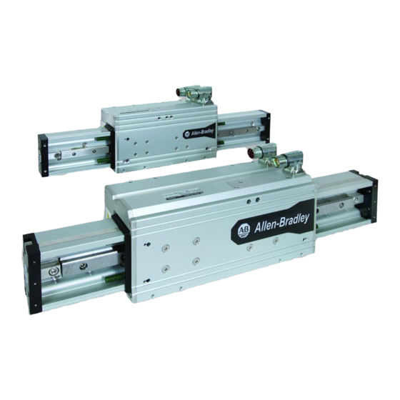
LDAT-Series Integrated Linear Thrusters
Catalog Numbers
LDAT Frame 30
LDAT Frame 50
LDAT-S03xxxx-DB
LDAT-S05xxxx-DB
LDAT-S03xxxx-DBS
LDAT-S05xxxx-DBS
LDAT-S03xxxx-EB
LDAT-S05xxxx-EB
LDAT-S03xxxx-EBS
LDAT-S05xxxx-EBS
LDAT-S03xxxx-DD
LDAT-S05xxxx-DD
LDAT-S03xxxx-DDS
LDAT-S05xxxx-DDS
LDAT-S03xxxx-ED
LDAT-S05xxxx-ED
LDAT-S03xxxx-EDS
LDAT-S05xxxx-EDS
Topic
Summary of Changes
Safety Considerations
Catalog Number Explanation
About the LDAT-Series Integrated Linear Thruster
Before You Begin
Install the Linear Thruster
Dimensions
Connector Data
Commissioning
Maintenance
Troubleshooting
Accessories
Replacement Parts
Install Replacement Parts
Interconnect Diagrams
Specifications
Additional Resources
LDAT Frame 75
LDAT Frame 100
LDAT-S07xxxx-DB
LDAT-S10xxxx-DB
LDAT-S07xxxx-DBS
LDAT-S10xxxx-DBS
LDAT-S07xxxx-EB
LDAT-S10xxxx-EB
LDAT-S07xxxx-EBS
LDAT-S10xxxx-EBS
LDAT-S07xxxx-DD
LDAT-S10xxxx-DD
LDAT-S07xxxx-DDS
LDAT-S10xxxx-DDS
LDAT-S07xxxx-ED
LDAT-S10xxxx-ED
LDAT-S07xxxx-EDS
LDAT-S10xxxx-EDS
LDAT Frame 150
LDAT-S15xxxx-DB
LDAT-S15xxxx-DBS
LDAT-S15xxxx-EB
LDAT-S15xxxx-EBS
LDAT-S15xxxx-DD
LDAT-S15xxxx-DDS
LDAT-S15xxxx-ED
LDAT-S15xxxx-EDS
Page
2
2
6
7
8
11
19
31
32
51
54
56
58
59
70
74
77
Advertisement
Table of Contents

Subscribe to Our Youtube Channel
Related Manuals for Rockwell Automation Allen-Bradley LDAT Series


Summary of Contents for Rockwell Automation Allen-Bradley LDAT Series
- Page 1 Installation Instructions Original Instructions LDAT-Series Integrated Linear Thrusters Catalog Numbers LDAT Frame 30 LDAT Frame 50 LDAT Frame 75 LDAT Frame 100 LDAT Frame 150 LDAT-S03xxxx-DB LDAT-S05xxxx-DB LDAT-S07xxxx-DB LDAT-S10xxxx-DB LDAT-S15xxxx-DB LDAT-S03xxxx-DBS LDAT-S05xxxx-DBS LDAT-S07xxxx-DBS LDAT-S10xxxx-DBS LDAT-S15xxxx-DBS LDAT-S03xxxx-EB LDAT-S05xxxx-EB LDAT-S07xxxx-EB LDAT-S10xxxx-EB LDAT-S15xxxx-EB LDAT-S03xxxx-EBS LDAT-S05xxxx-EBS LDAT-S07xxxx-EBS...
-
Page 2: Summary Of Changes
Tig ht t m ov te na ev en d m ain to pr n an lla tio in sta Product Nameplate Product Nameplate Rockwell Automation Publication LDAT-IN001B-EN-P - March 2020... -
Page 3: Safety Labels
High Energy Magnets Linear thruster magnet tracks contain high energy magnets that attract ferrous metals from a considerable distance. Precautions must be taken while unpacking, handling, and shipping by air. Rockwell Automation Publication LDAT-IN001B-EN-P - March 2020... - Page 4 Subsection 7.4.1: Magnetized Material Label • Section 8: Shipper's Declaration for Dangerous Goods When shipped via ground in the United States, these products are not considered a U.S. D.O.T. Hazardous Material and standard shipping procedures apply. Rockwell Automation Publication LDAT-IN001B-EN-P - March 2020...
- Page 5 SHOCK HAZARD: An assembled linear thruster will generate power if the coil or magnet track is moved. Un-terminated power cables present an electrical shock hazard. Never handle flying leads or touch power pins while moving the motor. Rockwell Automation Publication LDAT-IN001B-EN-P - March 2020...
-
Page 6: Catalog Number Explanation
(1) Magnetic strip has 1 mm pole pitch. Final resolution when used with a Kinetix® 300 servo drive is 0.488 μm. Absolute encoder is only compatible with Kinetix 300 single-axis drives. Accessories on page 56 for accessory catalog numbers. Rockwell Automation Publication LDAT-IN001B-EN-P - March 2020... - Page 7 Accessory feet side -mount threaded holes Grease access (not applicable on frame 30) Bottom surface threaded direct-mount holes Stator body ATTENTION: Magnetized tools can cause damage if they come too close to surface magnetic encoder scale tape. Rockwell Automation Publication LDAT-IN001B-EN-P - March 2020...
-
Page 8: Before You Begin
Failure to do so may result in personal injury and/or equipment damage. For your system’s specific weight, refer to the system nameplate label or shipping weights on the packing slip. Rockwell Automation Publication LDAT-IN001B-EN-P - March 2020... -
Page 9: Planning Your Installation
ANSI/RIA R15.06, Industrial Robots and Robot Systems Safety Requirements - Teaching Multiple Robots • ANSI/NFPA 79, Electrical Standard for Industrial Machinery • CSA/CAN Z434, Industrial Robots and Robot Systems- General Safety Requirements • EN60204-1, Safety of Machinery. Electrical Equipment of Machines Rockwell Automation Publication LDAT-IN001B-EN-P - March 2020... - Page 10 Unexpected slider movement can cause personal injury. 5. Lift the linear thruster. 6. Visually inspect the linear thruster for damage. Closely examine the mounting surface, frame, and slider for defects. 7. Notify the carrier of shipping damage immediately. Rockwell Automation Publication LDAT-IN001B-EN-P - March 2020...
-
Page 11: Preventing Electrical Noise
ATTENTION: Do not loosen the shipping and handling set screw until the linear thruster is installed in its application. ATTENTION: Install linear thruster to avoid interference with buildings, structures, utilities other machines and equipment may create a trapping hazard or pinch points. Rockwell Automation Publication LDAT-IN001B-EN-P - March 2020... - Page 12 Use these torque values to attach a rod eye, rod clevis or payload bracket to the slider. Cat. No. Torque, max LDAT-S03 LDAT-S05 6.8 N•m (5 lb•ft) LDAT-S07 LDAT-S10 14.7 N•m (10.83 lb•ft) LDAT-S15 (1) Unless otherwise noted, torque specifications have a ±20% tolerance. Rockwell Automation Publication LDAT-IN001B-EN-P - March 2020...
- Page 13 4. Install hex nut and spring anchor assemble in one of the three threaded mount locations. Torque nut to 33.9 N•m (25.0 lb•ft). 5. Remove three screws that secure the slider-end cap and discard. Rockwell Automation Publication LDAT-IN001B-EN-P - March 2020...
- Page 14 8. Screw one 3/8 in. hex nut onto a spring anchor. 9. Install hex nut and spring anchor assemble in the counter balance bracket. Torque nut to 33.9 N•m (25.0 lb•ft). Attach your counter balance spring between the two spring anchor pins. Rockwell Automation Publication LDAT-IN001B-EN-P - March 2020...
- Page 15 5. Torque the foot mount screw to linear thruster to the following values. Cat. No. Foot Mount Torque, max LDAT-S03 LDAT-S05 LDAT-SMID-FTMOUNT 4.5 N•m (3.33 lb•in) LDAT-S07 LDAT-S10 LDAT-SLARGE-FTMOUNT 6.8 N•m (5.00 lb•in) LDAT-S15 (1) Unless otherwise noted, torque specifications have a ±20% tolerance. Rockwell Automation Publication LDAT-IN001B-EN-P - March 2020...
- Page 16 ATTENTION: High voltage can be present on the shield of a power cable, if the shield is not grounded. Make sure there is a connection to ground for any power cable shield. Failure to observe these safety precautions could result in personal injury or damage to equipment. Rockwell Automation Publication LDAT-IN001B-EN-P - March 2020...
- Page 17 Power Connector Feedback Connector Flat Surface Feedback Connector Flat Surface with Logo on Top with Logo on Top Flat Surface Flat Surface with Logo on Top with Logo on Top Drip Loop Drip Loop Rockwell Automation Publication LDAT-IN001B-EN-P - March 2020...
-
Page 18: Change Connector Orientation
ATTENTION: Only apply force to the connectors; do not apply force to the cable. Do not use tools (for example, pliers and vise-grips) to assist with the rotation of the connector. Failure to observe these safety precautions could result in personal injury or damage to equipment. Rockwell Automation Publication LDAT-IN001B-EN-P - March 2020... - Page 19 LDAT-Series Integrated Linear Thrusters 19 Rockwell Automation Publication LDAT-IN001B-EN-P - March 2020...
- Page 20 20 LDAT-Series Integrated Linear Thrusters Rockwell Automation Publication LDAT-IN001B-EN-P - March 2020...
- Page 21 LDAT-Series Integrated Linear Thrusters 21 Rockwell Automation Publication LDAT-IN001B-EN-P - March 2020...
- Page 22 22 LDAT-Series Integrated Linear Thrusters Rockwell Automation Publication LDAT-IN001B-EN-P - March 2020...
- Page 23 LDAT-Series Integrated Linear Thrusters 23 Rockwell Automation Publication LDAT-IN001B-EN-P - March 2020...
- Page 24 24 LDAT-Series Integrated Linear Thrusters Rockwell Automation Publication LDAT-IN001B-EN-P - March 2020...
- Page 25 LDAT-Series Integrated Linear Thrusters 25 Rockwell Automation Publication LDAT-IN001B-EN-P - March 2020...
- Page 26 LDAT-Series Integrated Linear Thrusters 26 Rockwell Automation Publication LDAT-IN001B-EN-P - March 2020...
- Page 27 LDAT-Series Integrated Linear Thrusters 27 Rockwell Automation Publication LDAT-IN001B-EN-P - March 2020...
- Page 28 28 LDAT-Series Integrated Linear Thrusters Rockwell Automation Publication LDAT-IN001B-EN-P - March 2020...
- Page 29 LDAT-Series Integrated Linear Thrusters 29 Rockwell Automation Publication LDAT-IN001B-EN-P - March 2020...
- Page 30 30 LDAT-Series Integrated Linear Thrusters Rockwell Automation Publication LDAT-IN001B-EN-P - March 2020...
-
Page 31: Connector Data
Excessive and uneven lateral force at the cable connector may result in damage to the housing and contacts as the cable flexes. Failure to observe these safety precautions could result in damage to the motor and its components. Rockwell Automation Publication LDAT-IN001B-EN-P - March 2020... -
Page 32: Required Files
300 EtherNet/IP Indexing Servo Drives User Manual, publication 2097-UM001. Kinetix You can use Motion Analyzer software, version 6.0 or later as required. Download these files from http://www.rockwellautomation.com/support. Contact Rockwell Automation Technical Support at (440) 646-5800 for assistance. Rockwell Automation Publication LDAT-IN001B-EN-P - March 2020... - Page 33 You must verify that the servo control system safely controls the linear thruster with regard to maximum force, acceleration, and speed. Positive Motion Direction Positive motion is defined as the slider extending from the stator body opposite the power and feedback connectors. Rockwell Automation Publication LDAT-IN001B-EN-P - March 2020...
- Page 34 Systems using a 230V drive show linear thruster with a _A suffix and those using a 460V drive will show _B suffix. EXAMPLE LDAT -S031020-Bx_A catalog numbers are shown when 230V drive is selected. LDAT -S031020-Bx_B catalog numbers are shown when 460V drive is selected. Rockwell Automation Publication LDAT-IN001B-EN-P - March 2020...
- Page 35 For preliminary Autotune do not check tune parameter boxes. 3. Click Start Tuning. You can fine tune the linear thruster for your specific application requirements by using the suggestions made in the next section. Rockwell Automation Publication LDAT-IN001B-EN-P - March 2020...
- Page 36 ATTENTION: Avoid excessive force while homing the linear thruster. Do not exceed 100 mm/s (4.0 in/s) during a home routine. Speeds greater than 100 mm/s (4.0 in/s) may damage the linear thruster when the slider reaches the end of travel. Rockwell Automation Publication LDAT-IN001B-EN-P - March 2020...
- Page 37 Position Error and the Position Error Tolerance is set to a relatively large value, such as, the default value, the increase in Position Error may go undetected. If proper precautions are not in place, this could lead to equipment damage and/or serious injury. Rockwell Automation Publication LDAT-IN001B-EN-P - March 2020...
- Page 38 In your application run-time code, monitor the axis.MotorCapacity real time attribute. Drive Foldback occurs when axis.MotorCapacity reaches 108% of rated continuous torque. • Implement a program that brings your axis to a controlled stop before axis.MotorCapacity reaches 100%. Rockwell Automation Publication LDAT-IN001B-EN-P - March 2020...
- Page 39 Follow steps to do a hookup test for the linear thruster. 1. Set the Test Distance to 60 mm. 2. Click Start. 3. Verify that the Motor Polarity, Feedback Polarity and Motion Polarity are normal. Rockwell Automation Publication LDAT-IN001B-EN-P - March 2020...
- Page 40 Home The Kinetix 6500 drive does not support Home-to-Torque homing. Use this link to the Sample Code Library to download the AOI file called CIP Home to Torque. http://samplecode.rockwellautomation.com/idc/groups/public/documents/webassets/sc_legal _info.hcst?dID=75636 Rockwell Automation Publication LDAT-IN001B-EN-P - March 2020...
- Page 41 Follow these steps to do a hookup test for the linear thruster with an incremental encoder. ATTENTION: This procedure causes the linear thruster to move in the negative direction. 1. Position the slider in the center of travel. Rockwell Automation Publication LDAT-IN001B-EN-P - March 2020...
- Page 42 7. Set the Travel Limit to 50.0 User Units. 8. Click Start. The linear thruster will oscillate. To accept the autotune parameters, click Yes. 10. Adjust the Gain Scaling by adding -1. 11. Set the Feed back Filter to Off Rockwell Automation Publication LDAT-IN001B-EN-P - March 2020...
- Page 43 We recommend you wire a home switch to Input B1. Follow these steps to home the linear thruster. 1. Disable the axis. 2. From the General category set Drive Mode to Indexing. Rockwell Automation Publication LDAT-IN001B-EN-P - March 2020...
- Page 44 4. Double-click the Online Drive icon to view the main Drive setup dialog box. 5. From the Workspace, select Motor category. 6. Change the parameter Auto Motor Iden to Disabled. 7. From the Motor Model pull-down menu, select your linear thruster catalog number. Rockwell Automation Publication LDAT-IN001B-EN-P - March 2020...
- Page 45 3. Set the parameters to the following values. Parameter Value Motor Direction Bi-Directional Maximum Distance 10000 counts Step Current 4. Click Start Autotune. The Velocity Regulator Gains changes to reflect autotune values. The Autotune Complete status indicator turns yellow. Rockwell Automation Publication LDAT-IN001B-EN-P - March 2020...
- Page 46 6. Click Enable Drive. 7. Click Start Homing. The linear thruster moves to the negative spring stop and returns to the home position. The In Position and At Home display indicators turn yellow. Rockwell Automation Publication LDAT-IN001B-EN-P - March 2020...
-
Page 47: Setting Travel Limits
V = maximum velocity of stage in your application [m/s] (1) Velocity and kinetic energy can be much higher due to uncontrolled, worst-case motion that is only constrained by the length of stroke and the power capacity of the motor-drive pairing. Rockwell Automation Publication LDAT-IN001B-EN-P - March 2020... - Page 48 LDAT-S074070-xxx 16.8 (37.08) LDAT-S073020-xxx 9.5 (20.99) LDAT-S076010-xxx 12.0 (26.35) LDAT-S073030-xxx 10.7 (23.67) LDAT-S076020-xxx 13.2 (29.03) LDAT-S073040-xxx 12.0 (26.35) LDAT-S076030-xxx 14.4 (31.72) LDAT-S073050-xxx 13.2 (29.03) LDAT-S076040-xxx 15.6 (34.40) LDAT-S073060-xxx 14.4 (31.72) LDAT-S076050-xxx 16.8 (37.08) Rockwell Automation Publication LDAT-IN001B-EN-P - March 2020...
- Page 49 LDAT-S106040-xxx 25.2 (55.47) LDAT-S103050-xxx 21.2 (46.72) LDAT-S106050-xxx 27.1 (59.84) LDAT-S103060-xxx 23.2 (51.09) LDAT-S106060-xxx 29.1 (64.22) LDAT-S103070-xxx 25.2 (55.47) LDAT-S106070-xxx 31.1 (68.60) LDAT-S103080-xxx 27.1 (59.84) LDAT-S106080-xxx 33.1 (72.97) LDAT-S103090-xxx 29.1 (64.22) LDAT-S106090-xxx 35.1 (77.35) Rockwell Automation Publication LDAT-IN001B-EN-P - March 2020...
- Page 50 LDAT-S156040-xxx 38.4 (84.68) LDAT-S153050-xxx 32.3 (71.30) LDAT-S156050-xxx 41.4 (91.36) LDAT-S153060-xxx 35.4 (77.99) LDAT-S156060-xxx 44.5 (98.05) LDAT-S153070-xxx 38.4 (84.68) LDAT-S156070-xxx 47.5 (104.74) LDAT-S153080-xxx 41.4 (91.36) LDAT-S156080-xxx 50.5 (111.43) LDAT-S153090-xxx 44.5 (98.05) LDAT-S156090-xxx 53.6 (118.12) Rockwell Automation Publication LDAT-IN001B-EN-P - March 2020...
-
Page 51: Maintenance
Recommended maintenance and lubrication interval for frame 50, 75, 100, and 150 linear thrusters is every 6 months or 5000 km of travel, whichever comes first. Frame 30 linear thrusters are lubricated for life. Rockwell Automation Publication LDAT-IN001B-EN-P - March 2020... -
Page 52: Bearing Lubrication
8. Install the end clamps with the M3 x 0.5 x 6 mm button head cap screws. 9. Install the stator cover with the M3 x 0.5 x 6 mm flat head cap screws. 10. Torque all screws to 1.1 N•m (10 lb•in). Rockwell Automation Publication LDAT-IN001B-EN-P - March 2020... - Page 53 After six months of storage, cycle the linear thruster two complete strokes to redistribute the internal lubricants. • After storage for a period longer than two years without use, lubricant replacement is recommended, contact Rockwell Automation Technical Support. Rockwell Automation Publication LDAT-IN001B-EN-P - March 2020...
-
Page 54: Troubleshooting
Linear thruster is enabled but operating range of travel. If a particular location is erratically or not at all. malfunctioning, replace incremental Encoder magnetic strip is damaged encoder magnetic scale. If using an absolute encoder, return for repair. Rockwell Automation Publication LDAT-IN001B-EN-P - March 2020... - Page 55 RSLogix Software configuration matches linear thruster nameplate Kinetix 300 drive displays E07 while Install un-terminated motor feedback Not using correct feedback connector using linear thruster with absolute cable with LDAT-CONKIT-ABS connector accessory feedback option Rockwell Automation Publication LDAT-IN001B-EN-P - March 2020...
-
Page 56: Mounting Accessories
(1) Size and purchase spring according to your application needs. Guidance provided in Kinetix Linear Motion Technical Data, publication GMC-TD002. Mounting Accessories Accessory Item Frame Cat. No. Weight, approx g (oz) LDAT-SMID-FTMOUNT 30 (1.06) Foot Mount LDAT-SLARGE-FTMOUNT 40 (1.41) LDAT-S03-CLVSM 100 (3.53) LDAT-S0507-CLVSM 150 (5.29) Clevis, Male LDAT-S1015-CLVSM 370 (13.05) Rockwell Automation Publication LDAT-IN001B-EN-P - March 2020... - Page 57 LDAT-S1015-RODCPLR 1030 (36.33) LDAT-S03-HPBRKT 260 (9.17) LDAT-S0507-HPBRKT 430 (15.17) Horizontal Payload Mounting Bracket LDAT-S10-HPBRKT 910 (32.10) LDAT-S15-HPBRKT 1300 (54.86) LDAT-S03-CBRKT 380 (13.4) LDAT-S0507-CBRKT 600 (21.2) Counterbalance Kit LDAT-S10-CBRKT 950 (33.5) LDAT-S15-CBRKT 1160 (40.9) Rockwell Automation Publication LDAT-IN001B-EN-P - March 2020...
-
Page 58: Replacement Parts
LDAT = LDAT-Series Integrated Linear Thruster Encoder Replacement Components Cat. No. Description LDAT-TTL-ENC TTL Incremental encoder LDAT-TTL-SCALE Encoder scale tape, 170 cm (67 in.) Cat. No. Description MPAS-GPUMP Grease pump kit MPAS-CART Grease cartridge Rockwell Automation Publication LDAT-IN001B-EN-P - March 2020... - Page 59 3. Mount the encoder scale by following procedure on page 67. 4. Assemble the linear thruster by following procedure on page 62. 5. Check the encoder by following procedure on page 68. 6. Do the Hookup test by following procedure on page 69. Rockwell Automation Publication LDAT-IN001B-EN-P - March 2020...
- Page 60 1. If your linear thruster has the strip cover, option follow Remove Strip Cover procedure on page 66. 2. Loosen the shipping and handling set screw. 3. Remove the coil screws. 4. Remove the bearing screws. There are four screws per bearing. Rockwell Automation Publication LDAT-IN001B-EN-P - March 2020...
- Page 61 6. Remove the slider end cap opposite the connector side. 7. Remove the end stop bracket. 8. Remove screws that mount the power and feedback connectors to the stator body. 9. Slide the connectors out of the stator body. Rockwell Automation Publication LDAT-IN001B-EN-P - March 2020...
- Page 62 ATTENTION: Be sure the cables do not come in contact with the slider assembly when completing the assembly. Contact with moving parts will cause damage to the cables and premature failure of the linear thruster. 4. Loosely attach the coil to the stator body. Rockwell Automation Publication LDAT-IN001B-EN-P - March 2020...
-
Page 63: Repeat Step
Slide the slider assembly and verify the cables do not come in contact with it. 16. Attach the stator end cap. 17. If your linear thruster has the strip cover option, install the cover by following the Remove Strip Cover procedure on page in reverse. Rockwell Automation Publication LDAT-IN001B-EN-P - March 2020... - Page 64 Position the bearing pucks out of your way as necessary. 2. Remove the bearing rail. Install Bearing 1. Clean the bearing mounting and banking surface with isopropyl alcohol and a soft clean cloth. 2. Loosely install the new bearing rail. Rockwell Automation Publication LDAT-IN001B-EN-P - March 2020...
- Page 65 Leave the plastic bearing retainer in place until you are ready to assemble the puck to the rail. To assemble the frame 30 bearing pucks, do the following. a.Butt the plastic retainer against end of the rail. b.Slide the bearing from the retainer to the rail. Rockwell Automation Publication LDAT-IN001B-EN-P - March 2020...
- Page 66 4. If you are removing the strip cover to lubricate the linear thruster, you are finished. 5. If you are replacing the strip cover, do the following. Peel off the low-friction tape from the stator body and the stator cove and discard. Rockwell Automation Publication LDAT-IN001B-EN-P - March 2020...
- Page 67 2. Loosely install the new encoder on encoder bracket. Orient the encoder on the encoder bracket such that the cables exit towards the feedback connector. 3. Connect the encoder cable. 4. Install the encoder bracket assembly. Rockwell Automation Publication LDAT-IN001B-EN-P - March 2020...
- Page 68 6. Locate the axis tag ActualPosition. You will monitor this tag while doing the next step. 7. Move the linear thruster through its entire range of motion. Verify the position readout does not miscount. Rockwell Automation Publication LDAT-IN001B-EN-P - March 2020...
- Page 69 Lay the stainless steel backer flat to the slider. If the scale is not flat, the encoder scale will rub on the encoder. 5. Remove the paper backing from the encoder scale tape and place the scale tape on the stainless steel backer. Rockwell Automation Publication LDAT-IN001B-EN-P - March 2020...
-
Page 70: Interconnect Diagrams
Cable WHT/ORANGE Cable Shield Shield BLUE Thermostat Thermostat Clamp WHT/BLUE Clamp YELLOW WHT/YELLOW 2090-XXNFMF-Sxx (standard) or 2090-XXNFMF-Sxx (standard) or 2090-CFBM7DAFxx (continuous-flex) 2090-CFBM7DAFxx (continuous-flex) (flying-lead) Feedback Cable (flying-lead) Feedback Cable Note 2 Note 2 Rockwell Automation Publication LDAT-IN001B-EN-P - March 2020... - Page 71 ECOM Thermostat ORANGE +9VDC Thermostat WHT/ORANGE BLUE 2090-CFBM7DF-CEAAxx (standard), 2090-CFBM7DF-CEAAxx (standard), 2090-CFBM7DD-CEAAxx (standard), 2090-CFBM7DD-CEAAxx (standard), 2090-CFBM7DF-CEAFxx (continuous-flex) 2090-CFBM7DF-CEAFxx (continuous-flex) 2090-CFBM7DD-CEAFxx (continuous-flex) 2090-CFBM7DD-CEAFxx (continuous-flex) (flying-lead) Feedback Cable (flying-lead) Feedback Cable Note 3 Note 3 Rockwell Automation Publication LDAT-IN001B-EN-P - March 2020...
- Page 72 Brown Motor Power GREEN WHT/GREEN Motor Feedback +5VDC GRAY (MF) Connector Motor ECOM WHT/GRAY Feedback – ORANGE WHT/ORANGE Thermostat BLUE WHT/BLUE YELLOW WHT/YELLOW 2090-XXNFMF-Sxx (standard) or 2090-CFBM7DAFxx (continuous-flex) (flying-lead) Feedback Cable Note 2 Rockwell Automation Publication LDAT-IN001B-EN-P - March 2020...
- Page 73 Turn clamp over to hold small cable secure. secure. Use 2090-UXBB-DM15 connector Use 2090-UXBB-DM15 connector with Ultra3000 drives. with Ultra3000 drives. Exposed shield secured under Exposed shield secured under clamp. clamp. Cable Tie Cable Tie Rockwell Automation Publication LDAT-IN001B-EN-P - March 2020...
-
Page 74: Specifications
LDAT-S076050-xx 43.5 (95.8) LDAT-S072070-xx 25.0 (55.2) LDAT-S074030-xx 30.6 (67.5) LDAT-S076060-xx 44.7 (98.5) LDAT-S073010-xx 23.0 (50.7) LDAT-S074040-xx 31.8 (70.2) LDAT-S076070-xx 45.9 (101.2) LDAT-S073020-xx 24.2 (53.3) LDAT-S074050-xx 33.1 (72.9) LDAT-S073030-xx 25.4 (56.0) LDAT-S074060-xx 34.3 (75.6) Rockwell Automation Publication LDAT-IN001B-EN-P - March 2020... - Page 75 LDAT-S154030-xx 66.5 (146.6) LDAT-S156060-xx 97.6 (215.1) LDAT-S153010-xx 49.5 (109.2) LDAT-S154040-xx 69.5 (153.3) LDAT-S156070-xx 100.6 (221.8) LDAT-S153020-xx 52.6 (115.9) LDAT-S154050-xx 72.5 (159.9) LDAT-S156080-xx 103.7 (228.5) LDAT-S153030-xx 55.6 (122.6) LDAT-S154060-xx 75.6 (166.6) LDAT-S156090-xx 106.7 (235.2) Rockwell Automation Publication LDAT-IN001B-EN-P - March 2020...
-
Page 76: Environmental Specifications
20 g peak, 6 ms duration Vibration, max 2.5 g peak @ 30…2000 Hz (1) Tested for one hour per Rockwell Automation specification 10000056670. Contact your distributor for a copy of this specification. Rockwell Automation Publication LDAT-IN001B-EN-P - March 2020... -
Page 77: Additional Resources
GMC-RM001 minimize system failures caused by electrical noise. You can view or download publications at http://www.rockwellautomation.com/literature. To order paper copies of technical documentation, contact your local Allen-Bradley distributor or Rockwell Automation sales representative. Rockwell Automation Publication LDAT-IN001B-EN-P - March 2020... -
Page 78: Rockwell Automation Support
Rockwell Automation representative. New Product Satisfaction Return Rockwell Automation tests all of its products to ensure that they are fully operational when shipped from the manufacturing facility. However, if your product is not functioning and needs to be returned, follow these procedures.
Need help?
Do you have a question about the Allen-Bradley LDAT Series and is the answer not in the manual?
Questions and answers