Table of Contents
Advertisement
Quick Links
Advertisement
Table of Contents

Related Manuals for DAYLIFF DMS


Summary of Contents for DAYLIFF DMS
- Page 1 Horizontal Multistage Centrifugal Pumps Installation & Operating Manual...
- Page 3 INDEX PUMP SPECIFICATIONS 2. MOUNTING INSTALLATION PUMP OPERATION TROUBLE SHOOTING WARRANTY © Davis & Shirtliff Ltd 2021 Contents herein are not warranted...
-
Page 4: Pump Specifications
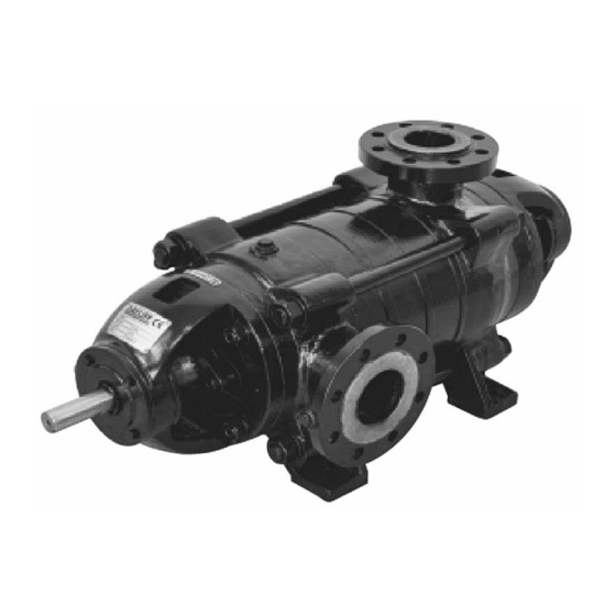
8 10 FLOW RATE (m /hr) PUMP The DAYLIFF DMS range of horizontal multistage centrifugal pumps are heavy duty industrial quality pumps suitable for various water supply, irrigation and industrial applications. Particular features include gland packing seals for simple and economical maintenance and external securing tie bolts for ease of disassembly. - Page 5 Rotation: Clockwise viewed from driving end STANDARD DIMENSIONS Inlet Flange Outlet Flange Dimensions (mm) Shaft Pump Size Inlet Outlet Holes Holes DMS 12 50 140 110 4X13.5 40 150 110 4X17.5 65 160 130 65 185 145 8X17.5 DMS 25 4X17.5 80 190 150 4X17.5 65 185 145 8X17.5...
- Page 6 2. MOUNTING Prime Mover Selection: It is essential to ensure correct prime mover selection as the pump unit will be inefficient if over sized and will overload if undersized. The power absorbed at the duty point should be read from the pump curve and an appropriately sized prime mover selected that allows for some spare power capacity (recommended 15%) to accommodate efficiency reductions as the installation ages.
-
Page 7: Installation
3. INSTALLATION 3. INSTALLATION Location: The pump should be installed as near as possible to the water and as a general rule the suction lift should be minimised to ensure maximum pumping efficiency. Foundation: To be sufficiently substantial to support the pump independently of piping and provide sufficient support to eliminate mounting bedplate distortion. -
Page 8: Pump Operation
Foot Valve: Unless there is a positive suction with the water surface above the pump centerline and a free water flow into the pump, a foot valve is required with an inlet area atleast 1 ½ times the area of the suction pipe. A strainer should have clear area of 3 or 4 times that of the suction pipe. -
Page 9: Troubleshooting
5. TROUBLE SHOOTING PROBLEM POSSIBLE CAUSE SOLUTION New Installation Discharge head too high Check both the static and friction head Check sufficient new positive suction Suction lift too great head available Old Installation Suction line and pump housing not See Pump Starting properly primed No flow Impeller, suction pipe or foot valve... -
Page 10: Terms Of Warranty
6. TERMS OF WARRANTY i) General Liability • In lieu of any warranty, condition or liability implied by law, the liability of Davis & Shirtliff (hereafter called the Company) in respect of any defect or failure of equipment supplied is limited to making good by replacement or repair (at the Company's discretion) defects which under proper use appear therein and arise solely from faulty design, materials or workmanship within a specified period. - Page 12 INS215A-08/11...
Need help?
Do you have a question about the DMS and is the answer not in the manual?
Questions and answers