Table of Contents
Advertisement
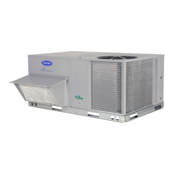
50HJQ004---007
50HEQ003---006
Single---Package Rooftop Heat Pump Units
CONTENTS
. . . . . . . . . . . . . . . . . . . . . . . . . . . . . . . .
. . . . . . . . . . . . . . . . . . . . . . . . . . . . .
. . . . . . . . . . . . . . . . . . . . . . . . . . . . . . . . . .
. . . . . . . . . . . . . . . . . . . . . . . . . . . . . . . . . .
. . . . . . . . . . . . . . . . . . . . . . . . . . . . . . .
. . . . . . . . . . . . . . . . . . . . . . . . . . . . . . . . . .
. . . . . . . . . . . . . . . . . . . . . . . . . . .
. . . . . . . . . . . . . . . . . . . . . . . . . . . . . . .
. . . . . . . . . . . . . . . . . . . . . . . . . . .
. . . . . . . . . . . . . . . . . . . . . . . . . .
. . . . . . . . . . . . . . . . . . . . . . . . . . . . . .
. . . . . . . . . . . . . . . . . . . . . . . . . . .
. . . . . . . . . . . . . . . . . . . . . . . . . . . . . . . . . . .
. . . . . . . . . . . . . . . . . . . . . . . . . . . . . . . . . . . . . . . .
. . . . . . . . . . . . . . . . . . . . . . . . . . . . . . . . . . . . . . . .
. . . . . . . . . . . . . . . . . . . . . . . . . . . . .
. . . . . . . . . . . . . . . . . . . . . . . . . . .
Installation, Start---Up and
Service Instructions
PAGE
. . . . . . . . . . . . . . . . . . . . . . . .
. . . . . . . . . . . . . . . . . . . . . . . . .
. . . . . . . . . . . . . . . . . . . . . . . . . .
. . . . . . . .
. . . . . . . . . . . . . . . . . . . . . . .
. . . . . . . . . . . . . . . . . . . . . . . . .
. . . . . . . . . . . . . . . . . . .
. . . . . . . . . . . . . . . . . .
. . . . . . . . . . . . . . . . . . . . . . . .
. . . . . . . .
. . . . . . . . . . . . . . . .
. . . . . . . . . . . . . . . . .
. . . . . . . . . . . . . . . . . . . . . . . . .
SAFETY CONSIDERATIONS
Installation and servicing of air-conditioning equipment can be
hazardous due to system pressure and electrical components.
1
Only trained and qualified service personnel should install, repair,
1-52
or service air-conditioning equipment.
1
Untrained personnel can perform basic maintenance functions of
cleaning coils and filters and replacing filters. All other operations
1
should be performed by trained service personnel. When working
3
on air-conditioning equipment, observe precautions in the
literature, tags and labels attached to the unit, and other safety
3
precautions that may apply.
3
Follow all safety codes. Wear safety glasses and work gloves. Use
3
quenching cloth for unbrazing operations. Have fire extinguisher
3
available for all brazing operations.
4
!
5
5
Before performing service or maintenance operations
on unit, turn off main power switch to unit, and install
21
lockout tag.
22
injury.
22
NOTE: Ensure that the voltage listed on the unit information
22
plate agrees with the electrical supply to the unit.
22
22
Unit is shipped in the vertical discharge configuration. To convert
to horizontal configuration, remove horizontal duct opening
22
covers. Using the same screws, install covers on duct openings in
23
basepan of unit with the insulation-side down. Seals around duct
26
openings must be tight.
STEP 1 -PROVIDE UNIT SUPPORT
28
ROOF CURB
29
Assemble and install the accessory roof curb in accordance with
34
the instructions shipped with the curb. (See Fig. 1.) Install
34
insulation, cant strips, roofing felt, and counter flashing as shown.
53
Ductwork must be attached to the curb, not to the unit. If electric
or control power will be routed through the basepan, attach the
53
accessory thru-the-bottom service connections to the basepan and
56
roof curb in accordance with the accessory installation
instructions. Install connections before the unit is set on the roof
61
curb.
66
IMPORTANT: The gasketing of the unit to the roof curb is critical
for water- -tightness. Install the gasket supplied with the roof curb as
shown in Fig. 1. An improperly applied gasket can also result in air
leaks and poor unit performance.
The roof curb should be level to ensure that the unit drain
functions properly. Unit leveling tolerances are shown in Fig. 2.
1
WARNING
Electrical shock could cause personal
INSTALLATION
Advertisement
Chapters
Table of Contents

Related Manuals for Carrier 50HJQ004


Summary of Contents for Carrier 50HJQ004
-
Page 1: Table Of Contents
50HJQ004---007 50HEQ003---006 Single---Package Rooftop Heat Pump Units Installation, Start---Up and Service Instructions CONTENTS SAFETY CONSIDERATIONS Installation and servicing of air-conditioning equipment can be PAGE hazardous due to system pressure and electrical components. SAFETY CONSIDERATIONS ...... - Page 2 D ALT ROOF CURB CONNECTOR CONTROL ACCESSORY UNIT SIZE DRAIN POWER ACCESSORY PKG. ACCY. POWER HOLE 1 -2 CRRFCURB001A01 CRBTMPWR001A01 [19] NPT [356] 50HJQ [19] NPT 004-007 CRBTMPWR002A01 [31.7] 2 -0 CRRFCURB002A01 [610] 1 -9 1 -4 [12.7] [12.7] CRBTMPWR003A01 [19] NPT [551] [406]...
-
Page 3: Slab Mount
like a star connection, but can be removed with a -in. socket drive extension. (See Fig. 3.) Complete the piping for the condensate drain and external trap after the unit is in place. All units must have an external trap for condensate drainage. Install a trap at least 4 in. -
Page 4: Positioning
NOTES: 1. Dimension in ( ) is in millimeters. 2. Hook rigging shackles through holes in base rail, as shown in detail ‘‘A.’’ Holes in base rails are centered around the unit center of gravity. Use wooden top skid when rigging to prevent rigging straps from damaging unit. 3. -
Page 5: Make Electrical Connections
Such operation electrical ground to minimize the possibility of personal invalidates any applicable Carrier warranty. injury if an electrical fault should occur. This ground may NOTE: If the unit is mounted on a roof curb and electrical consist of electrical wire connected to unit ground lug in power will be run up “thru-the-bottom,”... - Page 8 Table 1—Physical Data 50HJQ004- -007 50HJQ UNIT SIZE NOMINAL CAPACITY (tons) OPERATING WEIGHT (lb) Unit EconoMi$er IV Roof Curb COMPRESSOR Scroll Quantity Oil (oz) REFRIGERANT TYPE R-22 Operating Charge (lb) 12.0 12.0 18.3 17.7 OUTDOOR FAN Propeller Type Quantity...Diameter (in.) 1...22...
- Page 9 Table 2—Physical Data 50HEQ003- -006 50HEQ UNIT SIZE NOMINAL CAPACITY (tons) OPERATING WEIGHT (lb) Unit EconoMi$er IV Roof Curb COMPRESSOR Scroll Quantity Oil (oz) REFRIGERANT TYPE R-22 Operating Charge (lb) 12.0 12.0 18.3 OUTDOOR FAN Propeller Type Quantity...Diameter (in.) 1...22 1...22 1...22 1...22...
- Page 10 Electric Heating Capacitie Table 3— ACCESSORY HEATER SINGLE POINT BOX VOLTAGE ACCESSORY PART NUMBER PACKAGE NO. UNIT SIZE (60 Hz) (kW) CRHEATER --- ---A00 CRSINGLE --- ---A00 (or --- ---B00 where indicated) 3.3/4.4 --- --- 208/230 4.9/6.5 --- --- (2 Tons) (single phase) 6.5/8.7 003B00...
- Page 11 Table 4A — 50HJQ Electrical Data — Standard Motor Units Without Electrical Convenience Outlet MINIMUM UNIT VOLTAGE ELECTRIC POWER NOMINAL COMPRESSOR OFM IFM DISCONNECT UNIT RANGE HEAT* SUPPLY VOLTAGE SIZE SIZE V-PH-Hz Min Max FLA FLA kW† MOCP** 30/ 30 101/101 —/—...
- Page 12 Table 4B — 50HJQ Electrical Data — High-Static Motor Units Without Electrical Convenience Outlet MINIMUM UNIT VOLTAGE ELECTRIC POWER NOMINAL COMPRESSOR OFM IFM DISCONNECT RANGE HEAT* SUPPLY UNIT SIZE VOLTAGE SIZE V-PH-Hz Min Max kW† MOCP** 120/120 —/— —/— 19.4/ 19.4 20/20 19/ 19 129/130...
- Page 13 Table 4C — 50HJQ Electrical Data — Standard Motor Units With Electrical Convenience Outlet MINIMUM UNIT VOLTAGE ELECTRIC POWER NOMINAL COMPRESSOR DISCONNECT RANGE HEAT* SUPPLY UNIT SIZE VOLTAGE SIZE V-PH-Hz kW† MOCP** 35/ 35 106/106 —/— — 30.4/ 30.4 30/ 30 60/ 60 122/124 3.3/ 4.4...
- Page 14 Table 4D — 50HJQ Electrical Data — High-Static Motor Units With Electrical Convenience Outlet MINIMUM UNIT VOLTAGE ELECTRIC POWER NOMINAL COMPRESSOR DISCONNECT RANGE HEAT* SUPPLY UNIT SIZE VOLTAGE SIZE V-PH-Hz kW† MOCP** 25/ 25 124/124 —/— —/— 24.2/ 24.2 25/ 25 40/ 40 134/135 3.3/ 4.4...
- Page 15 LEGEND Example: Supply voltage is 460-3-60 FLA --- Full Load Amps HACR --- Heating, Air Conditioning and Refrigeration IFM --- Indoor ---Fan Motor LRA --- Locked Rotor Amps MCA --- Minimum Circuit Amps MOCP --- Maximum Overcurrent Protection NEC --- National Electrical Code AB = 452 v OFM --- Outdoor ---Fan Motor BC = 464 v...
- Page 16 Table 5A — 50HEQ Electrical Data — Standard Motor Units Without Electrical Convenience Outlet MINIMUM UNIT VOLTAGE ELECTRIC POWER NOMINAL COMPRESSOR OFM IFM DISCONNECT RANGE HEAT* SUPPLY UNIT SIZE VOLTAGE SIZE V-PH-Hz Min Max FLA FLA kW† MOCP 20/ 20** 69/69 —/—...
- Page 17 Table 5B — 50HEQ Electrical Data — High-Static Motor Units Without Electrical Convenience Outlet MINIMUM UNIT VOLTAGE ELECTRIC POWER NOMINAL COMPRESSOR OFM IFM DISCONNECT UNIT RANGE HEAT* SUPPLY VOLTAGE SIZE SIZE V-PH-Hz Min Max FLA FLA kW† MOCP** 120/120 —/— —/—...
- Page 18 Table 5C — 50HEQ Electrical Data — Standard Motor Units With Electrical Convenience Outlet MINIMUM UNIT VOLTAGE ELECTRIC POWER NOMINAL COMPRESSOR DISCONNECT RANGE HEAT* SUPPLY UNIT SIZE VOLTAGE SIZE V-PH-Hz kW† MOCP** 25/ 25 73/73 —/— — 21.1/ 21.1 21/ 21 45/ 45 89/92 3.3/ 4.4...
- Page 19 Table 5D — 50HEQ Electrical Data — High-Static Motor Units With Electrical Convenience Outlet MINIMUM UNIT VOLTAGE ELECTRIC POWER NOMINAL COMPRESSOR DISCONNECT RANGE HEAT* SUPPLY UNIT SIZE VOLTAGE SIZE V-PH-Hz kW† MOCP** 25/ 25 124/124 —/— —/— 24.2/ 24.2 25/ 25 40/ 40 134/135 3.3/ 4.4...
- Page 20 LEGEND Example: Supply voltage is 460-3-60 FLA --- Full Load Amps HACR --- Heating, Air Conditioning and Refrigeration IFM --- Indoor ---Fan Motor LRA --- Locked Rotor Amps MCA --- Minimum Circuit Amps MOCP --- Maximum Overcurrent Protection NEC --- National Electrical Code AB = 452 v OFM --- Outdoor ---Fan Motor BC = 464 v...
-
Page 21: Field Control Wiring
Without Economizer or Two- -Position Damper NOTE: If using a Carrier electronic thermostat, set the thermostat configuration for “non-heat pump operation.” This family of products does not require the O terminal to energize the reversing valve. -
Page 22: Defrost Board
Route the thermostat cable or equivalent single leads of colored wire from the subbase terminals to the low-voltage connections on the unit (shown in Fig. 9 and 10) as described in Steps 1 and 2 below. NOTE: For wire runs up to 50 ft, use no. 18 AWG (American Wire gauge) insulated wire (35_C minimum). -
Page 23: Premierlinkt Control
Fig. 14 --- Outdoor- -Air Hood Details The PremierLink controller (See Fig. 17 and 18) requires the use of a Carrier electronic thermostat or a CCN connection for time 6. Remove and save the 8 screws (4 on each side) from the broadcast to initiate its internal timeclock. - Page 24 Table 6 — PremierLink™ Sensor Usage OUTDOOR AIR RETURN AIR OUTDOOR AIR RETURN AIR APPLICATION TEMPERATURE SENSOR TEMPERATURE SENSOR ENTHALPY SENSOR ENTHALPY SENSOR Dry Bulb Temperature with PremierLink* Included --- — — — (PremierLink HH79NZ017 requires 4-20 mA Actuator) Differential Dry Bulb Temperature with Required --- Included ---...
- Page 25 C06016 Fig. 17 --- Factory Installed PremierLinkt Controller PREMIERLINK CONTROL HINGED DOOR PANEL C06017 Fig. 18 --- Factory Installed PremierLinkt (Shown Installed on Unit with Hinged Access Panel Option) Outdoor Air Enthalphy Sensor/Enthalpy Controller 1. Use a 4-conductor, 18 or 20 AWG cable to connect the enthalpy control to the PremierLink™...
-
Page 26: Optional Economi$Er Iv And Economi$Er2
(2) on enthalpy sensor. NOTE: These instructions are for installing the optional NOTE: If installing in a Carrier rooftop, use the two gray wires EconoMi$er IV and EconoMi$er2 only. Refer to the accessory provided from the control section to the economizer to connect EconoMi$er IV or EconoMi$er2 installation instructions when PremierLink controller to terminals 2 and 3 on enthalpy sensor. - Page 27 OUTDOOR AIR HOOD ENTHALPY CONTROLLER (OUTDOOR ENTHALPY SENSOR) ECONOMI$ER2 HOOD PLUG SHIPPING (RETURN AIR BRACKET ENTHALPY SENSOR) GRAY/ORN WIRE HARNESS IN UNIT GRAY/RED NOTES: 1. Remove factory-installed jumper across SR and + before connecting GEAR DRIVEN wires from return air sensor. BAROMETRIC DAMPER 2.
-
Page 28: Economi$Er Iv Standard Sensors
7. Open the filter clips which are located underneath the hood top. Insert the aluminum filter into the bottom filter rack (hood divider). Push the filter into position past the open filter clips. Close the filter clips to lock the filter into place. -
Page 29: Economi$Er Iv Control Modes
FOR OCCUPANCY CONTROL REPLACE JUMPER WITH FIELD-SUPPLIED TIME CLOCK LEGEND Potentiometer Defaults Settings: NOTES: Power Exhaust Middle 1. 620 ohm, 1 watt 5% resistor should be removed only when using differential DCV— Demand Controlled Ventilation Minimum Pos. Fully Closed enthalpy or dry bulb. IAQ —... - Page 30 Table 8 — EconoMi$er IV Sensor Usage ECONOMI$ER IV WITH OUTDOOR AIR DRY BULB SENSOR APPLICATION Accessories Required Outdoor Air Dry Bulb None. The outdoor air dry bulb sensor is factory installed. Differential Dry Bulb CRTEMPSN002A00* Single Enthalpy HH57AC078 Differential Enthalpy HH57AC078 and CRENTDIF004A00* for DCV Control using a 33ZCSENCO2...
- Page 31 airstream is used for cooling. When using this mode of AQ1 terminals of the controller. Adjust the DCV potentiometers changeover control, turn the enthalpy setpoint potentiometer fully to correspond to the DCV voltage output of the indoor air quality clockwise to the D setting. (See Fig. 35.) sensor at the user-determined set point.
- Page 32 (29) (32) (35) (38) (41) (43) CONTROL CONTROL POINT CURVE APPROX. deg. F (deg. C) AT 50% RH (27) 73 (23) 70 (21) 67 (19) 63 (17) (24) (21) (18) (16) (13) (10) HIGH LIMIT CURVE (10) (13) (16) (18) (21) (24) (27)
- Page 33 occupied mode. When the timeclock contacts are open (removing the 24-v signal from terminal N), the EconoMi$er IV will be in unoccupied mode. Demand Controlled Ventilation (DCV) 24 Vac When using the EconoMi$er IV for demand controlled ventilation, there are some equipment selection criteria which should be considered.
-
Page 34: Adjust Indoor- -Fan Speed
For some applications, a device such as a 62AQ energy recovery unit is Use setting 1 or 2 for Carrier equipment. (See Table 9.) added to reduce the moisture content of the fresh air being 1. - Page 35 To change fan speed: 3. Loosen the movable pulley flange setscrew. (See Fig. 42.) 1. Shut off the unit power supply and tag disconnect. 4. Screw the movable flange toward the fixed flange to increase speed or away from the fixed flange to decrease 2.
- Page 36 Unit warranty will not be affected. Table 13A — Accessory Electric Heaters Static Pressure Drop (in. wg) — 50HJQ004-007 and 50HEQ003- -006...
- Page 37 2. Values include losses for filters, unit casing, and wet coils. See Tables 13A and 13B for accessory/FIOP static pressure information. 3. Use of a field-supplied motor may affect wire sizing. Contact your Carrier representative for details. 4. Interpolation is permissible. Do not extrapolate.
- Page 38 Table 17 — Fan Performance 50HEQ004, 50HJQ004 — Vertical Discharge Units; High-Static Motor (Belt Drive)* EXTERNAL STATIC PRESSURE (in. wg) AIRFLOW (Cfm) Watts Watts Watts Watts Watts 0.14 0.23 0.32 0.42 0.52 1000 0.17 0.27 0.37 0.47 0.58 1100 0.21 0.31...
- Page 39 Table 19 — Fan Performance 50HEQ005, 50HJQ005 — Vertical Discharge Units; High-Static Motor (Belt Drive)* EXTERNAL STATIC PRESSURE (in. wg) AIRFLOW (Cfm) Watts Watts Watts Watts Watts 1200 0.25 0.36 0.48 0.60 1031 0.72 1300 0.30 0.42 0.54 0.67 1057 0.80 1400 0.36...
- Page 40 Table 20 — Fan Performance 50HEQ006, 50HJQ006 — Vertical Discharge Units; Standard Motor (Belt Drive)* — Single-Phase Units EXTERNAL STATIC PRESSURE (in. wg) AIRFLOW (Cfm) Watt Watts Watts Watts Watts 1500 0.40 0.53 0.68 1075 0.83 1152 1.00 1600 0.46 0.60 1022 0.75...
- Page 41 Table 21 — Fan Performance 50HEQ006, 50HJQ006 — Vertical Discharge Units; Standard Motor (Belt Drive)* — Three-Phase Units EXTERNAL STATIC PRESSURE (in. wg) AIRFLOW (Cfm) Watt Watts Watts Watts Watts 1500 0.40 0.53 0.68 1075 0.83 1152 1.00 1600 0.46 0.60 1022 0.75...
- Page 42 Table 22 — Fan Performance 50HEQ006, 50HJQ006 — Vertical Discharge Units; High-Static Motor (Belt Drive)* EXTERNAL STATIC PRESSURE (in. wg) AIRFLOW (Cfm) Watt Watts Watts Watts Watts 1500 0.40 0.53 0.68 1075 0.83 1152 1.00 1600 0.46 0.60 1022 0.75 1104 0.92 1180...
- Page 43 Table 23 — Fan Performance 50HJQ007 — Vertical Discharge Units; Standard Motor (Belt Drive)* EXTERNAL STATIC PRESSURE (in. wg) AIRFLOW (Cfm) Watt Watts Watts Watts Watts 1800 0.63 1006 0.80 1092 0.97 1169 1.14 1015 1239 1.32 1174 1900 0.72 1042 0.90 1126...
- Page 44 Table 24 — Fan Performance 50HJQ007 — Vertical Discharge Units; High-Static Motor (Belt Drive)* EXTERNAL STATIC PRESSURE (in. wg) AIRFLOW (Cfm) Watt Watts Watts Watts Watts 1800 0.63 1006 0.80 1092 0.97 1169 1.14 1015 1239 1.32 1174 1900 0.72 1042 0.90 1126...
- Page 45 0.14 0.22 0.32 0.42 1000 0.58 0.15 0.16 0.26 0.36 0.47 Table 26 — Fan Performance 50HEQ004, 50HJQ004 — Horizontal Discharge Units; Standard Motor (Belt Drive)* EXTERNAL STATIC PRESSURE (in. wg) AIRFLOW (Cfm) Watts Watts Watts Watts Watts 0.14 0.22 0.32...
- Page 46 Table 27 — Fan Performance 50HEQ004, 50HJQ004 — Horizontal Discharge Units; High-Static Motor (Belt Drive)* EXTERNAL STATIC PRESSURE (in. wg) AIRFLOW (Cfm) Watts Watts Watts Watts Watts 0.14 0.22 0.32 0.42 0.53 1000 0.16 0.26 0.36 0.47 0.58 1100 0.20 0.30...
-
Page 47: Watts Rpm Bhp 1200 643 0.23 233
Table 29 — Fan Performance 50HEQ005, 50HJQ005 — Horizontal Discharge Units; High-Static Motor (Belt Drive)* EXTERNAL STATIC PRESSURE (in. wg) AIRFLOW (Cfm) Watts Watts Watts Watts Watts 1200 0.23 0.35 0.46 0.58 1020 0.71 1300 0.28 0.40 0.52 0.65 1045 0.78 1400 0.33... -
Page 48: Airflow (Cfm)
Table 30 — Fan Performance 50HEQ006, 50HJQ006 — Horizontal Discharge Units; Standard Motor (Belt Drive)* — Single-Phase Units EXTERNAL STATIC PRESSURE (in. wg) AIRFLOW (Cfm) Watt Watts Watts Watts Watts 1500 0.33 0.45 0.59 1028 0.74 1111 0.91 1600 0.39 0.51 0.65 1050... - Page 49 Table 31 — Fan Performance 50HEQ006, 50HJQ006 — Horizontal Discharge Units; Standard Motor (Belt Drive)* — Three-Phase Units EXTERNAL STATIC PRESSURE (in. wg) AIRFLOW (Cfm) Watts Watts Watts Watts Watts 1500 0.33 0.45 0.59 1028 0.74 1111 0.91 1600 0.39 0.51 0.65 1050...
-
Page 50: Bhp Watts
Table 32 — Fan Performance 50HEQ006, 50HJQ006 — Horizontal Discharge Units; High-Static Motor (Belt Drive)* EXTERNAL STATIC PRESSURE (in. wg) AIRFLOW (Cfm) Watts Watts Watts Watts Watts 1500 0.33 0.45 0.59 1028 0.74 1111 0.91 1600 0.39 0.51 0.65 1050 0.81 1132 0.98... - Page 51 Table 33 — Fan Performance 50HJQ007 — Horizontal Discharge Units; Standard Motor (Belt Drive)* EXTERNAL STATIC PRESSURE (in. wg) AIRFLOW (Cfm) Watts Watts Watts Watts Watts 1800 0.51 0.66 1018 0.82 1100 0.98 1174 1.15 1024 1900 0.59 0.74 1046 0.91 1127 1.08...
- Page 52 Table 34 — Fan Performance 50HJQ007 — Horizontal Discharge Units; High-Static Motor (Belt Drive)* EXTERNAL STATIC PRESSURE (in. wg) AIRFLOW (Cfm) Watts Watts Watts Watts Watts 1800 0.51 0.66 1018 0.82 1100 0.98 1174 1.15 1024 1900 0.59 0.74 1046 0.91 1127 1.08...
-
Page 53: Pre-Start-Up
PRE-START-UP START-UP STEP 1 —UNIT PREPARATION WARNING Make sure that the unit has been installed in accordance with installation instructions and applicable codes. Failure to observe the following warnings could result in STEP 2 —RETURN- - AIR FILTERS serious personal injury: Make sure the correct filters are installed in the unit (See Table 1). - Page 54 Compressor restart is accomplished by manual reset at the will come back open to the minimum open position once the thermostat by turning the selector switch to OFF position and supply-air temperature rises to 48_F. then to ON position. If optional power exhaust is installed, as the outdoor-air damper Allow unit to operate a minimum of 10 minutes before checking opens and closes, the power exhaust fans will be energized and refrigerant charge.
- Page 55 Routine 2 (DXCTLO < OAT < 68_F) OAT must be less than SPT. If only Y1 energized, the economizer maintains a Enthalpy must be LOW (may be jumpered if and SASP = (SATLO1 + 3). enthalpy sensor is not available). If SAT >...
-
Page 56: Service
If Heating PID STAGES=3 and AUXOUT = HS3 HEAT STAGES=1 (33% capacity) will energize HS1 HEAT STAGES=2 (66% capacity) will energize HS2 HEAT STAGES=3 (100% capacity) will energize HS3 In order to prevent short cycling, the unit is locked into the Heating mode for at least 10 minutes when HS1 is deenergized. - Page 57 Amount of refrigerant charge is listed on unit nameplate (also more often if operating conditions require it. Replacement filters refer to Table 1). Refer to Carrier Refrigerant Service Techniques must be the same dimensions as the original filters. Manual, Refrigerants section.
- Page 58 A complete list of replacement parts may be obtained from any Carrier distributor. C06049 Fig. 50 --- Cooling Charging Chart- -- -50HJQ005 C06048 Fig. 49 --- Cooling Charging Chart- -- -50HJQ004 C06050 Fig. 51 --- Cooling Charging Chart- -- -50HJQ006...
- Page 59 C06051 Fig. 52 --- Cooling Charging Chart- -- -50HJQ007 OUTDOOR TEMP Suction Line Temperature (deg C) 14.4 19.4 24.4 100.00 95.00 648.16 90.00 598.16 85.00 80.00 548.16 75.00 498.16 70.00 65.00 448.16 40.00 45.00 50.00 55.00 60.00 65.00 70.00 75.00 80.00 Suction Line Temperature (deg F) C06054...
- Page 60 OUTDOOR TEMP Suction Line Temperature (deg C) 14.44 19.44 24.44 4.44 9.44 100.00 95.00 648.16 90.00 598.16 85.00 80.00 548.16 75.00 498.16 70.00 65.00 448.16 40.00 45.00 50.00 55.00 60.00 65.00 70.00 75.00 80.00 C06055 Fig. 54 --- Cooling Charging Chart- -- -50HEQ004 OUTDOOR TEMP Suction Line Temperature (deg C)
-
Page 61: Troubleshooting
11. Set enthalpy potentiometer to D. Typical settings, sensor ranges, and jumper positions are also 12. Apply power (24 vac) to terminals TR and TR1. shown. An EconoMi$er IV simulator program is available from DIFFERENTIAL ENTHALPY Carrier help with EconoMi$er training To check differential enthalpy: troubleshooting. - Page 62 4. Return EconoMi$er IV settings and wiring to normal SUPPLY- -AIR INPUT after completing troubleshooting. To check supply-air input: DCV (DEMAND CONTROLLED VENTILATION) AND 1. Make sure EconoMi$er IV preparation procedure has been POWER EXHAUST performed. To check DCV and Power Exhaust: 2.
- Page 63 NOTES: 1. If any of the original wire furnished must be replaced, it must be replaced with type 90 C wire or its equivalent. 2. Three-phase motors are protected under pri- mary single phasing conditions. 3. Use copper conductors only. 4.
- Page 64 Table 35 — Heating and Cooling Troubleshooting PROBLEM CAUSE REMEDY Compressor and Power failure. Call power company. Outdoor Fan Fuse blown or circuit breaker tripped. Replace fuse or reset circuit breaker. Determine root cause. Will Not Start. Defective thermostat, contactor, transformer, Replace component.
- Page 65 Table 36 — EconoMi$er IV Input/Output Logic INPUTS OUTPUTS Enthalpy* Compressor N Terminal† Demand Control Stage Stage Occupied Unoccupied Outdoor Return Ventilation (DCV) Damper Below set High On On Minimum position Closed (DCV LED Off) (Free Cooling LED Off) On Off Off Off High On On...
-
Page 66: Start-Up Checklist
Catalog No:50HEQ,HJQ- - 1SI Printed in U.S.A. Edition Date:6/06 Copyright 2006 Carrier Corp. S 7310 W. Morris St. S Indianapolis, IN 46231 Replaces:50HJQ- -16SI Manufacturer reserves the right to change, at any time, specifications and designs without notice and without obligations.