Table of Contents
Advertisement
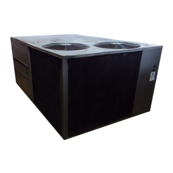
Single-Package Rooftop Cooling Units
CONTENTS
SAFETY CONSIDERATIONS . . . . . . . . . . . . . . . . . 1
INSTALLATION . . . . . . . . . . . . . . . . . . . . . . . . . . . . 1-26
Step 1- Provide Unit Support . . . . . . . . . . . . . . 1
• SLAB MOUNT
Step 2 - Field Fabricate Ductwork . . . . . . . . . . 1
and External Trap . . . . . . . . . . . . . . . . . . . . . . . . . 3
Step 4 - Rig and Place Unit . . . . . . . . . . . . . . . . 3
• POSITIONING
Step 5 - Make Electrical Connections . . . . . . 7
Options . . . . . . . . . . . . . . . . . . . . . . . . . . . . . . . . . . . 11
Step 7 - Adjust Evaporator-Fan Speed . . . . . 16
PRE-START-UP . . . . . . . . . . . . . . . . . . . . . . . . . . . . 26
START-UP . . . . . . . . . . . . . . . . . . . . . . . . . . . . . . . . 26-28
SERVICE . . . . . . . . . . . . . . . . . . . . . . . . . . . . . . . . . . 28-34
TROUBLESHOOTING . . . . . . . . . . . . . . . . . . . . . . 34-37
START-UP CHECKLIST . . . . . . . . . . . . . . . . . . . . . CL-1
SAFETY CONSIDERATIONS
Installation and servicing of air-conditioning equipment
can be hazardous due to system pressure and electrical com-
ponents. Only trained and qualified service personnel should
install, repair, or service air-conditioning equipment.
Untrained personnel can perform basic maintenance func-
tions of cleaning coils and filters and replacing filters. All
other operations should be performed by trained service per-
sonnel. When working on air-conditioning equipment, ob-
serve precautions in the literature, tags and labels attached
to the unit, and other safety precautions that may apply.
Follow all safety codes. Wear safety glasses and work gloves.
Use quenching cloth for unbrazing operations. Have fire ex-
tinguisher available for all brazing operations.
Before performing service or maintenance operations on
unit, turn off main power switch to unit. Electrical shock
could cause personal injury.
Manufacturer reserves the right to discontinue, or change at any time, specifications or designs without notice and without incurring obligations.
Book 1 4
PC 111
Tab
1b 6b
Installation, Start-Up and
Service Instructions
Page
Catalog No. 565-083
Printed in U.S.A.
50HJ008-014
INSTALLATION
Unit is shipped in the vertical configuration. To convert to
horizontal configuration, remove side duct opening covers.
Using the same screws, install covers on vertical duct open-
ings with the insulation-side down. Seals around duct open-
ings must be tight.
Step 1 - Provide Unit Support
ROOF CURB - Assemble and install accessory roof curb
in accordance with instructions shipped with curb. See Fig. 1.
Install insulation, cant strips, roofing felt, and counter flash-
ing as shown. Ductwork must be attached to curb. If electric
or control power is to be routed through the basepan, attach
the accessory thru-the-bottom service connections to the basepan
in accordance with the accessory installation instructions. Con-
nections must be installed before unit is set on roof curb.
IMPORTANT: The gasketing of the unit to the roof
curb is critical for a watertight seal. Install gasket sup-
plied with the roof curb as shown in Fig. 1. Improp-
erly applied gasket can also result in air leaks and poor
unit performance.
Curb should be level. This is necessary for unit drain to
function properly. Unit leveling tolerances are shown in
Fig. 2. Refer to Accessory Roof Curb Installation Instruc-
tions for additional information as required.
SLAB MOUNT (Horizontal Units Only) - Provide a level
concrete slab that extends a minimum of 6 in. beyond unit
cabinet. Install a gravel apron in front of condenser coil air
inlet to prevent grass and foliage from obstructing airflow.
NOTE: Horizontal units may be installed on a roof curb if
required.
Step 2 - Field Fabricate Ductwork -
cal discharge units, secure all ducts to roof curb and building
structure. Do not connect ductwork to unit. For horizontal
applications, field-supplied flanges should be attached to hori-
zontal discharge openings and all ductwork attached to the
flanges. Insulate and weatherproof all external ductwork, joints,
and roof openings with counter flashing and mastic in ac-
cordance with applicable codes.
Ducts passing through an unconditioned space must be
insulated and covered with a vapor barrier.
If a plenum return is used on a vertical unit, the return
should be ducted through the roof deck to comply with ap-
plicable fire codes.
Form 50HJ-15SI
Pg 1
On verti-
10-96
Replaces: 50HJ-14SI
Advertisement
Table of Contents

Related Manuals for Carrier 50HJ008-014


Summary of Contents for Carrier 50HJ008-014
-
Page 1: Table Of Contents
50HJ008-014 Single-Package Rooftop Cooling Units Installation, Start-Up and Service Instructions CONTENTS INSTALLATION Page Unit is shipped in the vertical configuration. To convert to SAFETY CONSIDERATIONS ....1 horizontal configuration, remove side duct opening covers. -
Page 2: Roof Curb
CONNECTION SIZES CONNECTOR UNIT SIZE D ALT POWER CONTROL ACCESSORY 50HJ DRAIN HOLE CONNECTION CONNECTION PACKAGE CRBTMPWR00A100 ⁄ ⁄ (Thru-the-Bottom) 008-014 2 -8 ⁄ [827] 1 -10 ⁄ [583] ⁄ [45] CRBTMPWR00A200 ⁄ ⁄ (Thru-the-Bottom) UNIT SIZE ROOF CURB 50HJ ACCESSORY 1 -2 [356] CRRFCURB003A00... -
Page 3: Step 3 - Install Condensate Drain Line And External Trap
MAXIMUM ALLOWABLE DIFFERENCE (in.) Fig. 2 — Unit Leveling Tolerance Fig. 3 — Condensate Drain Location A minimum clearance to combustibles is not required around ductwork on vertical discharge units. On horizontal dis- charge units, a minimum clearance of 1 in. is required for the first 12 in. - Page 4 NOTES: MAX WEIGHT 1. Dimension in ( ) is in millimeters. 50HJ 2. Hook rigging shackles through holes in base rail, as shown in de- tail A. Holes in base rails are centered around the unit center of 77.42 1967 41.5 1054 42.12 1070 gravity.
- Page 5 Table 1 — Physical Data UNIT 50HJ NOMINAL CAPACITY (tons) ⁄ ⁄ ⁄ OPERATING WEIGHT (lb) Unit With Durablade Economizer With Parablade Economizer With MoistureMiser Dehumidification Package Roof Curb COMPRESSOR Scroll Quantity Oil (oz) (each compressor) REFRIGERANT TYPE R-22 Operating Charge (lb-oz) Standard Unit Circuit 1 7-10...
- Page 6 DURABLADE PARABLADE CORNER CORNER CORNER CORNER STD UNIT ECONOMIZER ECONOMIZER WEIGHT WEIGHT WEIGHT WEIGHT ‘‘H’’ ‘‘J’’ ‘‘K’’ UNIT WEIGHT WEIGHT WEIGHT 50HJ ft-in. ft-in. ft-in. 2 -0 ⁄ 3 -5 ⁄ 1050 2 -9 ⁄ 1 -2 ⁄ 3 -5 ⁄...
-
Page 7: Step 5 - Make Electrical Connections
Carrier warranty. tails are provided for field wire connections. Use factory- supplied splices or UL (Underwriters’ Laboratories) approved copper/aluminum connector. 50HJ014, 208/230-3-60 50HJ008-012, 208/230-3-60 50HJ008-014, 460-3-60 LEGEND — Contactor COMP(S) — Compressors — Indoor (Evaporator) Fan Contactor — National Electrical Code —... - Page 8 Table 2A — Electrical Data (Units Without Electrical Convenience Outlet) VOLTAGE COMPRESSOR ELECTRIC POWER MINIMUM UNIT NOMINAL VOLTAGE RANGE (each) (each) HEAT* SUPPLY DISCONNECT SIZE UNIT (V-Ph-Hz) FLA Nominal kW† MOCP — — 38.2/ 38.2 45/ 45** 40/ 40 7.8/10.4 21.7/ 25.0 38.2/ 40.6 45/ 45**...
- Page 9 Table 2B – Electrical Data (Units With Electrical Convenience Outlet) VOLTAGE COMPRESSOR ELECTRIC POWER MINIMUM UNIT NOMINAL VOLTAGE RANGE (each) (each) HEAT* SUPPLY DISCONNECT SIZE UNIT (V-Ph-Hz) FLA Nominal kW† MOCP – – 44.2/ 44.2 50/ 50** 46/ 46 7.8/10.4 21.7/ 25.0 44.2/ 45.6 50/ 50**...
-
Page 10: Field Control Wiring
= 100 x max voltage deviation from average voltage average voltage 3. 575-v units have UL, Canada, approval only. FIELD CONTROL WIRING — Install a Carrier-approved accessory thermostat assembly according to installation in- structions included with the accessory. Locate thermostat as-... -
Page 11: Heat Anticipator Settings
(evaporator) fan status, filter status, and indoor-air quality. The Apollo control is designed to work with Carrier TEMP and VVT systems. The thermostat must be wired to the Apollo control before % RELATIVE HUMIDITY starting the unit. - Page 12 LEGEND — Contactor (compressor) — Crankcase Heater COMP — Compressor — Fuse — Humidistat — Indoor (Evaporator) Fan Motor LLSV — Liquid Line Solenoid Valve S-LPS — Low Pressure Switch (Subcooler only) TRAN — Transformer Factory Wiring Accessory or Optional Wiring Fig.
- Page 13 6. To convert to horizontal discharge application: 11. Fasten hood top and side plate assembly to outdoor-air opening panel with screws provided and install bottom a. Rotate the economizer 90 degrees until the econo- stop. mizer motor faces the condenser section (see Fig.
-
Page 14: Optional Parablade Economizer
ECONOMIZER CONTROL BOARD ECONOMIZER MOTOR WIRING HARNESS Fig. 17 — Horizontal Durablade Economizer Installation (90 Degree Rotation) Fig. 20 — Durablade Economizer Minimum Position Damper Setting OPTIONAL PARABLADE ECONOMIZER — The op- tional Parablade economizer hood assembly is packaged and shipped in the filter section. - Page 15 Fig. 22 — Wiring Connections for Outdoor-Air Thermostat Fig. 23 — Durablade Economizer Barometric Relief Damper Characteristics ECONOMIZER CONTROL MODULE/DAMPER ACTUATOR Fig. 24 — Parablade Economizer Installed in Unit dampers should be fully closed. Turn the potentiom- eter gradually counterclockwise until the desired po- sition is reached.
-
Page 16: Step 7 - Adjust Evaporator-Fan Speed
Insert the data into the following equations: T 1 (cfm 1 ) + T 2 (cfm 2 ) = T 3 cfm 3 cfm 2 = (cfm 3 – cfm 1 ) Therefore: T 1 (cfm 1 ) + T 2 (cfm 3 – cfm 1 ) = T 3 cfm 3 Use this equation to determine cfm 1 , which is the... - Page 17 MOTOR MOUNTING PLATE NUTS Fig. 30 — Typical Belt-Drive Motor Mounting for Sizes 008,009 Fig. 29 — Parablade Economizer Barometric Relief Damper Characteristics Table 4 shows evaporator-fan motor data. Table 5 shows fan rpm at motor pulley settings for standard and alternate mo- tors.
- Page 18 1. Boldface indicates a field-supplied drive is required. (See Note 6.) 5. Use of a field-supplied motor may affect wire sizing. Contact Carrier representative to verify. indicates field-supplied motor and drive are required. 6. Motor drive range: 840 to 1085 rpm. All other rpms require field- supplied drive.
- Page 19 1. Boldface indicates a field-supplied drive is required. (See Note 6.) 5. Use of a field-supplied motor may affect wire sizing. Contact Carrier representative to verify. indicates field-supplied motor and drive are required. 6. Motor drive range: 840 to 1085 rpm. All other rpms require field- supplied drive.
- Page 20 1. Boldface indicates a field-supplied drive is required. (See Note 6.) 5. Use of a field-supplied motor may affect wire sizing. Contact Carrier representative to verify. indicates field-supplied motor and drive are required. 6. Motor drive range: 860 to 1080 rpm. All other rpms require field- supplied drive.
- Page 21 1. Boldface indicates alternate drive is required. (See Note 6.) 5. Use of a field-supplied motor may affect wire sizing. Contact Carrier representative to verify. indicates alternate motor and drive cannot be used. 6. Standard motor drive range: 900 to 1260 rpm. Alternate motor drive range: 860 to 1080 rpm.
- Page 22 5. Use of a field-supplied motor may affect wire sizing. Contact 1. Boldface indicates a field-supplied drive is required. (See Note 6.) Carrier representative to verify. 6. Motor drive range: 840 to 1085 rpm. All other rpms require field- indicates field-supplied motor and drive are required.
- Page 23 1. Boldface indicates a field-supplied drive is required. (See Note 6.) 5. Use of a field-supplied motor may affect wire sizing. Contact Carrier representative to verify. indicates field-supplied motor and drive are required. 6. Motor drive range: 840 to 1085 rpm. All other rpms require field- supplied drive.
- Page 24 1. Boldface indicates a field-supplied drive is required. (See Note 6.) 5. Use of a field-supplied motor may affect wire sizing. Contact Carrier representative to verify. indicates field-supplied motor and drive are required. 6. Motor drive range: 860 to 1080 rpm. All other rpms require field- supplied drive.
- Page 25 1. Boldface indicates alternate drive is required. (See Note 6.) 5 Use of a field-supplied motor may affect wire sizing. Contact Carrier representative to verify. indicates alternate motor and drive cannot be used. 6 Standard motor drive range: 900 to 1260 rpm. Alternate motor drive range: 860 to 1080 rpm.
-
Page 26: Pre-Start-Up
Table 14 — Accessory/FIOP Economizer and b. Inspect for oil at all refrigerant tubing connections and Electric Heaters Static Pressure Drop (in. wg) on unit base. Detecting oil generally indicates a re- frigerant leak. Leak-test all refrigerant tubing connec- COMPO- tions using electronic leak detector, halide torch, or NENT 2200 2500 3000 3500 4000 4500 5000 5500 6000... - Page 27 is deenergized, the damper moves to the fully closed Cooling — To start unit, turn on main power supply. Set position. system selector switch at COOL position and fan switch at AUTO position. Adjust thermostat to a setting below room When the outdoor-air temperature is below the OAT set- temperature.
-
Page 28: Service
UNITS WITH MOISTUREMISER DEHUMIDIFICATION SERVICE PACKAGE — When thermostat calls for cooling, terminals G and Y1 and/or Y2 and the compressor contactor(s) C1 (and C2) are energized. The indoor (evaporator) fan motor When servicing unit, shut off all electrical power to unit (IFM), compressor(s), and outdoor (condenser) fan motors to avoid shock hazard or injury from rotating parts. - Page 29 Fig. 33 — MoistureMiser Option Operation...
- Page 30 Refrigerant Charge — Amount of refrigerant charge is listed on unit nameplate (also refer to Table 1). Refer to Carrier Standard Service Techniques Manual, Chapter 1, Re- frigerants section. Unit panels must be in place when unit is operating dur- ing charging procedure.
- Page 31 MOISTUREMISER SYSTEM CHARGING — The system temperature is high, add refrigerant. If suction temperature charge for units with the MoistureMiser option is greater than is low, carefully recover some of the charge. Recheck the that of the standard unit alone. The charge for units with this suction pressure as charge is adjusted.
- Page 32 Fig. 39 — Cooling Charging Chart, Standard 50HJ009 Fig. 40 — Cooling Charging Charts, Standard 50HJ012...
- Page 33 Fig. 41 — Cooling Charging Charts, Standard 50HJ014 Fig. 42 — Cooling Charging Chart, 50HJ008 Fig. 43 — Cooling Charging Chart, 50HJ009 with Optional MoistureMiser with Optional MoistureMiser Dehumidification Package Dehumidification Package...
-
Page 34: Troubleshooting
Fig. 45 — Cooling Charging Chart, 50HJ014 Fig. 44 — Cooling Charging Chart, 50HJ012 with Optional MoistureMiser with Optional MoistureMiser Dehumidification Package Dehumidification Package TROUBLESHOOTING Refer to Tables 16-19 for Troubleshooting details. Table 16 — MoistureMiser Dehumidification Subcooler Service Analysis PROBLEM CAUSE REMEDY... - Page 35 Table 17 — Cooling Troubleshooting PROBLEM CAUSE REMEDY Compressor(s) and Power failure. Call power company. condenser fans Fuse blown or circuit breaker tripped. Replace fuse or reset circuit breaker. will not start. Defective thermostat, contactor, transformer, or control Replace component. relay.
- Page 36 Table 18 — Durablade Economizer Troubleshooting PROBLEM CAUSE REMEDY Damper does not Evaporator fan is off. 1. Check to ensure that 24 vac is present at terminal C1 on the IFC or that 24 vac open. is present at the IFO terminal. Check whether 24 vac is present at PL6-1 (red wire) and/or PL6-3 (black wire).
- Page 37 Table 19 — Parablade Economizer Troubleshooting PROBLEM CAUSE REMEDY Damper does not Evaporator fan not on. Check wiring between G on connection board and evaporator-fan contactor. open. No power to economizer 1. Disconnect power at TR and TR1. Disconnect jumper across P and P1. motor.
- Page 38 For a free Service Training Material Catalog (STM), call 1-800-962-9212. Ordering instructions are included. Copyright 1996 Carrier Corporation Manufacturer reserves the right to discontinue, or change at any time, specifications or designs without notice and without incurring obligations. Book 1 4 PC 111 Catalog No.
-
Page 40: Start-Up Checklist
VERIFY THAT 3-PHASE SCROLL COMPRESSOR IS ROTATING IN CORRECT DIRECTION VERIFY REFRIGERANT CHARGE USING CHARGING CHARTS ON PAGES 31-34. Copyright 1996 Carrier Corporation Manufacturer reserves the right to discontinue, or change at any time, specifications or designs without notice and without incurring obligations.
Need help?
Do you have a question about the 50HJ008-014 and is the answer not in the manual?
Questions and answers