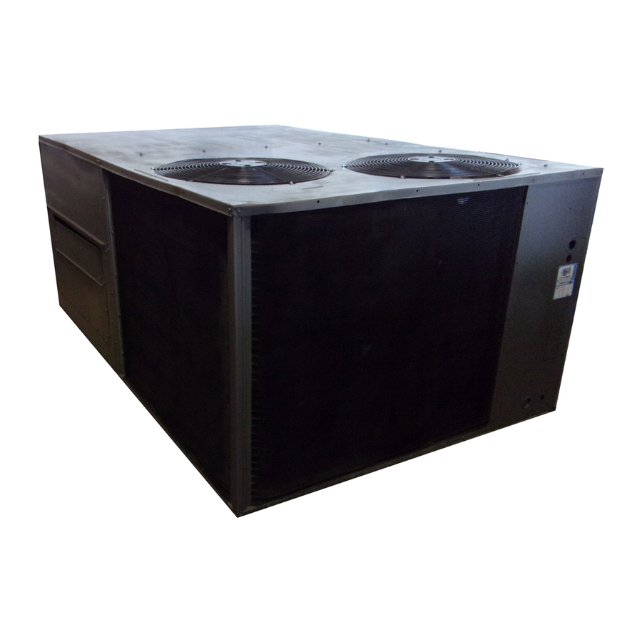
Carrier 50HJ008 Installation, Start-Up And Service Instructions Manual
Single-package rooftop electric cooling units
Hide thumbs
Also See for 50HJ008:
- Installation, start-up and service instructions manual (58 pages) ,
- Installation instructions manual (24 pages)
Table of Contents
Advertisement
CONTENTS
SAFETY CONSIDERATIONS . . . . . . . . . . . . . . . . . . . . . . 1
INSTALLATION . . . . . . . . . . . . . . . . . . . . . . . . . . . . . . . . 1-46
Step 1 — Provide Unit Support . . . . . . . . . . . . . . . . . . . 1
• ROOF CURB
• SLAB MOUNT
• ALTERNATE UNIT SUPPORT
Step 2 — Field Fabricate Ductwork . . . . . . . . . . . . . . . 2
Step 3 — Install Condensate Drain Line
and External Trap . . . . . . . . . . . . . . . . . . . . . . . . . . . . . . 2
Step 4 — Rig and Place Unit . . . . . . . . . . . . . . . . . . . . . 4
• POSITIONING
Step 5 — Make Electrical Connections . . . . . . . . . . . 7
• FIELD POWER SUPPLY
• FIELD CONTROL WIRING
• HEAT ANTICIPATOR SETTINGS
Step 6 — Adjust Factory-Installed
Options . . . . . . . . . . . . . . . . . . . . . . . . . . . . . . . . . . . . . . . 12
• HUMIDI-MIZER™ ADAPTIVE DEHUMIDIFICA-
TION SYSTEM
• DISCONNECT SWITCH
• CONVENIENCE OUTLET
• NOVAR CONTROLS
• MANUAL OUTDOOR-AIR DAMPER
• PREMIERLINK™ CONTROL
• OPTIONAL ECONOMI$ER IV AND ECONOMI$ER2
• ECONOMI$ER IV STANDARD SENSORS
• ECONOMI$ER IV CONTROL MODES
Step 7 — Adjust Evaporator-Fan Speed . . . . . . . . . 25
Pre-Start-Up . . . . . . . . . . . . . . . . . . . . . . . . . . . . . . . . . . 43
Start-Up . . . . . . . . . . . . . . . . . . . . . . . . . . . . . . . . . . . . 43-47
Service . . . . . . . . . . . . . . . . . . . . . . . . . . . . . . . . . . . . . 47-51
Troubleshooting. . . . . . . . . . . . . . . . . . . . . . . . . 52-55
Index . . . . . . . . . . . . . . . . . . . . . . . . . . . . . . . . . . . . . . . . . . . 56
Start-Up Checklist . . . . . . . . . . . . . . . . . . . . . . . . CL-1
SAFETY CONSIDERATIONS
Installation and servicing of air-conditioning equipment can
be hazardous due to system pressure and electrical compo-
nents. Only trained and qualified service personnel should
install, repair, or service air-conditioning equipment.
Untrained personnel can perform basic maintenance func-
tions of cleaning coils and filters and replacing filters. All other
operations should be performed by trained service personnel.
When working on air-conditioning equipment, observe precau-
tions in the literature, tags and labels attached to the unit, and
other safety precautions that may apply.
Follow all safety codes. Wear safety glasses and work
gloves. Use quenching cloth for unbrazing operations. Have
fire extinguisher available for all brazing operations.
Manufacturer reserves the right to discontinue, or change at any time, specifications or designs without notice and without incurring obligations.
Catalog No. 04-53500015-01
Book 1
4
Tab
1b 6b
Installation, Start-Up and
Service Instructions
Page
Printed in U.S.A.
Single-Package Rooftop
Electric Cooling Units
Ensure voltage listed on unit data plate agrees with electri-
cal supply provided for the unit.
Before performing service or maintenance operations on
unit, turn off main power switch to unit and install lockout
tag. Electrical shock could cause personal injury.
INSTALLATION
Unit is shipped in the vertical configuration. To convert to
horizontal configuration, remove side duct opening covers. Us-
ing the same screws, install covers on vertical duct openings
with the insulation-side down. Seals around duct openings
must be tight. See Fig. 1.
Step 1 — Provide Unit Support
ROOF CURB — Assemble and install accessory roof curb in
accordance with instructions shipped with curb. See Fig. 2.
Install insulation, cant strips, roofing felt, and counter flashing
as shown. Ductwork must be attached to curb. If electric or
control power is to be routed through the basepan, attach the
accessory thru-the-bottom service connections to the basepan
in accordance with the accessory installation instructions. Con-
nections must be installed before unit is set on roof curb.
IMPORTANT: The gasketing of the unit to the roof curb
is critical for a watertight seal. Install gasket supplied
with the roof curb as shown in Fig. 2. Improperly
applied gasket can also result in air leaks and poor unit
performance.
Curb should be level. This is necessary for unit drain to
function properly. Unit leveling tolerances are shown in Fig. 3.
Refer to Accessory Roof Curb Installation Instructions for
additional information as required.
SLAB MOUNT (Horizontal Units Only) — Provide a level
concrete slab that extends a minimum of 6 in. beyond unit
cabinet. Install a gravel apron in front of condenser coil air inlet
to prevent grass and foliage from obstructing airflow.
NOTE: Horizontal units may be installed on a roof curb if
required.
ALTERNATE UNIT SUPPORT — When the curb or adapter
cannot be used, support unit with sleeper rails using unit curb
or adapter support area. If sleepers cannot be used, support the
long sides of the unit with a minimum of 3 equally spaced
4-in. x 4-in. pads on each side.
Form 50HJ-32SI
Pg 1
50HJ008-014
9-05
Replaces: 50HJ-28SI
Advertisement
Table of Contents
Troubleshooting

Subscribe to Our Youtube Channel
Related Manuals for Carrier 50HJ008


Summary of Contents for Carrier 50HJ008
- Page 1 50HJ008-014 Single-Package Rooftop Electric Cooling Units Installation, Start-Up and Service Instructions CONTENTS Page SAFETY CONSIDERATIONS ..... . 1 Ensure voltage listed on unit data plate agrees with electri- cal supply provided for the unit.
-
Page 2: Installation
Fig. 1 — Horizontal Conversion Panels Step 2 — Field Fabricate Ductwork — Step 3 — Install Condensate Drain Line and On vertical discharge units, secure all ducts to roof curb and building External Trap — Condensate drain connections are locat- structure. - Page 3 D ALT CONNECTOR ACCESSORY ROOF CURB UNIT “A” DRAIN POWER CONTROL PKG ACCY ACCESSORY SIZE HOLE CRRFCURB003A01 1′-2″ [356] ″ [19] NPT 50HJ ″ CRBTMPWR001A01 008-014 ″ [31.7] CRRFCURB004A01 2′-0″ [610] [19] NPT CRBTMPWR002A01 ″ ″ ″ ″ ″ ″ 2′-8 1′-10 ″...
-
Page 4: Step 4 — Rig And Place Unit
Step 4 — Rig and Place Unit — After unit is in position, remove polyethylene shipping Inspect unit for trans- wrapper and rigging skid. portation damage. File any claim with transportation agency. Keep unit upright and do not drop. Spreader bars are not re- quired if top crating is left on unit. - Page 6 Table 1 — Physical Data UNIT 50HJ NOMINAL CAPACITY (tons) OPERATING WEIGHT (lb) Unit EconoMi$er IV Humidi-MiZer™ Adaptive Dehumidification System Roof Curb COMPRESSOR Scroll Quantity Oil (oz) (each compressor) REFRIGERANT TYPE R-22 Expansion Device Acutrol™ Metering Device Operating Charge (lb-oz) Standard Unit Circuit 1 7-10...
-
Page 7: Step 5 — Make Electrical Connections
200-v red terminal of the transformer. The to electrical components. Such operation would invalidate any end of the orange wire must then be insulated. applicable Carrier warranty. Refer to unit label diagram for additional information. See Table 3 for electric heater and single point box usage. - Page 8 25.1 — 16.5 19.8 29.1 — 44.0 44.0 27.8 33.4 46.0 — 33.0 39.7 53.9 — 41.7 50.2 66.9 — 50HJ008 — — 21.9 — 13.9 16.7 28.5 — 16.5 19.8 31.8 — 44.0 44.0 27.8 33.4 48.7 — 33.0 39.7...
- Page 9 Table 2 — Electrical Data (cont) VOLTAGE ELECTRIC HEATER POWER SUPPLY DISCONNECT COMP NO. 1 COMP NO. 2 RANGE SIZE† Fuse NOMINAL CONV UNIT Nominal V-PH-Hz TYPE OUTLET MOCP HACR — — 18.2 — 44.0 44.0 17.0 16.4 23.8 — 34.0 32.7 44.3...
- Page 10 LEGEND AND NOTES FOR TABLE 2 LEGEND Example: Supply voltage is 460-3-60. — Full Load Amps AB = 452 v HACR — Heating, Air Conditioning and Refrigeration BC = 464 v — Indoor (Evaporator) Fan Motor AC = 455 v —...
-
Page 11: Field Control Wiring
(Units with PremierLink™ Controls) connection kit is required. This is available through the local Carrier distributor. This kit is required to ensure a reliable water-tight connection. 2. If unit is mounted on roof curb and accessory thru-the-... -
Page 12: Options
Step 6 — Adjust Factory-Installed Options HUMIDI-MIZER™ ADAPTIVE DEHUMIDIFICATION SYSTEM — Humidi-MiZer adaptive dehumidification system operation can be controlled by field installation of a Carrier- approved humidistat (Fig. 11). To install the humidistat: NOTE: A light commercial Thermidistat™ control (Fig. 12) can be used instead of a humidistat if desired. -
Page 13: Tion System
LEGEND — Circuit Breaker TRAN — Transformer — Cooling Relay Field Splice — Dehumidify Relay — Discharge Solenoid Valve Terminal (Unmarked) — Heater Relay Splice — Humidistat — Low Pressure Switch Factory Wiring — Liquid Solenoid Valve Field Control Wiring LTLO —... -
Page 14: Hj008
Marquee can be used with the PremierLink controller. The PremierLink controller (see Fig. 19 and 20) requires the use of a Carrier electronic thermostat or a CCN connection for time broadcast to initiate its internal timeclock. This is neces- sary for broadcast of time of day functions (occupied/ unoccu- pied). - Page 15 NOTE: PremierLink™ controller versions 1.3 and later are shipped in Sensor mode. If used with a thermostat, the Pre- mierLink controller must be configured to Thermostat mode. Install the Supply Air Temperature (SAT) Sensor — When the unit is supplied with a factory-mounted PremierLink con- trol, the supply-air temperature (SAT) sensor (33ZCSENSAT) is factory-supplied and wired.
- Page 16 PREMIERLINK CONTROL HINGED DOOR PANEL Fig. 20 — PremierLink™ Controller (Installed) Table 5 — PremierLink Sensor Usage OUTDOOR AIR RETURN AIR OUTDOOR AIR RETURN AIR APPLICATION TEMPERATURE SENSOR TEMPERATURE SENSOR ENTHALPY SENSOR ENTHALPY SENSOR Differential Dry Bulb Temperature with Required — PremierLink* Included —...
- Page 17 Link controller and to terminal (2) on enthalpy sensor. differential enthalpy control to work properly. NOTE: If installing in a Carrier rooftop, use the two gray wires The enthalpy control receives the indoor and return provided from the control section to the economizer to connect enthalpy from the outdoor and return air enthalpy sensors and PremierLink controller to terminals 2 and 3 on enthalpy sensor.
- Page 18 ENTHALPY CONTROLLER (OUTDOOR ECONOMI$ER IV CONTROLLER ENTHALPY SENSOR) OUTSIDE AIR WIRING TEMPERATURE SENSOR HARNESS LOW AMBIENT (RETURN AIR SENSOR ENTHALPY ACTUATOR SENSOR) GRAY/ORN WIRE HARNESS IN UNIT GRAY/RED NOTES: 1. Remove factory-installed jumper across SR and + before connecting wires from return air sensor. 2.
- Page 19 3. The indoor coil access panel will be used as the top of the hood. Remove the screws along the sides and bottom of 22 1/4” the indoor coil access panel. See Fig. 28. 4. Swing out indoor coil access panel and insert the hood sides under the panel (hood top).
- Page 20 FOR OCCUPANCY CONTROL REPLACE JUMPER WITH FIELD-SUPPLIED TIME CLOCK LEGEND Potentiometer Defaults Settings: NOTES: Power Exhaust Middle 1. 620 ohm, 1 watt 5% resistor should be removed only when using differential DCV— Demand Controlled Ventilation Minimum Pos. Fully Closed enthalpy or dry bulb. IAQ —...
- Page 21 ECONOMI$ER IV CONTROL MODES 2500 IMPORTANT: The optional EconoMi$er2 does not include a controller. The EconoMi$er2 is operated by a 4 to 2000 20 mA signal from an existing field-supplied controller 1500 (such as PremierLink™ control). See Fig. 32 for wiring information.
- Page 22 sensor with the accessory enthalpy sensor in the same mount- ing location. See Fig. 24. When the outdoor air enthalpy rises above the outdoor enthalpy changeover set point, the outdoor- air damper moves to its minimum position. The outdoor enthalpy changeover set point is set with the outdoor enthalpy set point potentiometer on the EconoMi$er IV controller.
- Page 23 (29) (32) (35) (38) (41) (43) CONTROL CONTROL POINT CURVE APPROX. °F (°C) AT 50% RH (27) 73 (23) 70 (21) 67 (19) 63 (17) (24) (21) (18) (16) (13) (10) HIGH LIMIT CURVE (10) (13) (16) (18) (21) (24) (27) (29) (32)
- Page 24 See Table 8. EconoMi$er IV control will be in occupied mode. When the Use setting 1 or 2 for Carrier equipment. See Table 8. timeclock contacts are open (removing the 24-v signal from 1. Press Clear and Mode buttons. Hold at least 5 seconds terminal N), the EconoMi$er IV will be in unoccupied mode.
-
Page 25: Step 7 — Adjust Evaporator-Fan Speed
For units with electric heat, required minimum cfm is 2250 5. Set movable flange at nearest keyway of pulley hub and for 50HJ008,009 and 3000 for 50HJ012 and 014. See Table 9 tighten setscrew. (See Table 1 for speed change for each for exceptions. - Page 26 0.35 0.25 0.15 7.5 ton 0.05 8.5, 10 & 12.5 ton 4000 1000 2000 3000 5000 6000 Fig. 43 — Humidi-MiZer™ Adaptive Dehumidification System Static Pressure Drop (in. wg) To align fan and motor pulleys: 1. Loosen fan pulley setscrews. 2.
- Page 27 Table 10 — Fan Rpm at Motor Pulley Setting*; Standard Motor/Drive MOTOR PULLEY TURNS OPEN UNIT 50HJ 008,009 1085 1060 1035 1010 — — 1080 1060 1035 1015 — — 1130 1112 1087 1062 1037 1012 *Approximate fan rpm shown. Table 11 —...
- Page 28 Fan Performance tables to determine indoor blower rpm and watts. Table 15 — Accessory Electric Heaters Static Pressure Drop (in. wg) — 50HJ008-014 COMPONENT 2200 2500 3000 3500 4000 4500 5000 5500 6000 0.05...
- Page 29 Table 16 — Fan Performance 50HJ008 — Vertical Discharge Units; Standard Motor (Belt Drive)* EXTERNAL STATIC PRESSURE (in. wg) AIRFLOW Watts Watts Watts Watts Watts 2250 0.53 0.73 0.95 1.19 1106 1.44 1342 2300 0.56 0.76 0.98 1.22 1140 1.48...
- Page 30 Table 17 — Fan Performance 50HJ008 — Vertical Discharge Units; High-Static Motor (Belt Drive)* EXTERNAL STATIC PRESSURE (in. wg) AIRFLOW Watts Watts Watts Watts Watts 2250 0.53 0.73 0.95 1.19 1106 1.44 1342 2300 0.56 0.76 0.98 1.22 1140 1.48...
- Page 31 Table 18 — Fan Performance 50HJ009 — Vertical Discharge Units; Standard Motor (Belt Drive)* EXTERNAL STATIC PRESSURE (in. wg) AIRFLOW Watts Watts Watts Watts Watts 2500 0.41 0.54 0.67 0.80 0.93 2600 0.45 0.59 0.72 0.85 0.99 2700 0.50 0.64 0.77 0.91 1.05...
- Page 32 Table 19 — Fan Performance 50HJ009 — Vertical Discharge Units; High-Static Motor (Belt Drive)* EXTERNAL STATIC PRESSURE (in. wg) AIRFLOW Watts Watts Watts Watts Watts 2500 0.41 0.54 0.67 0.80 0.93 2600 0.45 0.59 0.72 0.85 0.99 2700 0.50 0.64 0.77 0.91 1.05...
- Page 33 Table 20 — Fan Performance 50HJ012 — Vertical Discharge Units; Standard Motor (Belt Drive)* EXTERNAL STATIC PRESSURE (in. wg) AIRFLOW Watts Watts Watts Watts Watts 3000 0.65 0.80 0.95 1.11 1034 1.26 1177 3100 0.70 0.86 1.02 1.18 1100 1.34 1249 3200 0.76...
- Page 34 Table 21 — Fan Performance 50HJ012 — Vertical Discharge Units; High-Static Motor (Belt Drive)* EXTERNAL STATIC PRESSURE (in. wg) AIRFLOW Watts Watts Watts Watts Watts 3000 0.65 0.80 0.95 1.11 1034 1.26 1177 3100 0.70 0.86 1.02 1.18 1100 1.34 1249 3200 0.76...
- Page 35 Table 22 — Fan Performance 50HJ014 — Vertical Discharge Units; Standard Motor (Belt Drive)* EXTERNAL STATIC PRESSURE (in. wg) AIRFLOW Watts Watts Watts Watts Watts 3700 1.11 1040 1.31 1218 1.50 1395 1.69 1571 1.87 1748 3800 1.20 1116 1.39 1299 1.59 1481...
- Page 36 Table 23 — Fan Performance 50HJ008 — Horizontal Discharge Units; Standard Motor (Belt Drive)* EXTERNAL STATIC PRESSURE (in. wg) AIRFLOW Watts Watts Watts Watts Watts 2250 0.43 0.64 0.86 1.10 1021 1.34 1252 2300 0.45 0.66 0.89 1.13 1050 1.38...
- Page 37 Table 24 — Fan Performance 50HJ008 — Horizontal Discharge Units; High-Static Motor (Belt Drive)* EXTERNAL STATIC PRESSURE (in. wg) AIRFLOW Watts Watts Watts Watts Watts 2250 0.43 0.64 0.86 1.10 1021 1.34 1252 2300 0.45 0.66 0.89 1.13 1050 1.38...
- Page 38 Table 25 — Fan Performance 50HJ009 — Horizontal Discharge Units; Standard Motor (Belt Drive)* EXTERNAL STATIC PRESSURE (in. wg) AIRFLOW Watts Watts Watts Watts Watts 2500 0.37 0.50 0.64 0.78 0.93 2600 0.41 0.54 0.68 0.83 0.98 2700 0.45 0.58 0.73 0.88 1.04...
- Page 39 Table 26 — Fan Performance 50HJ009 — Horizontal Discharge Units; High-Static Motor (Belt Drive)* EXTERNAL STATIC PRESSURE (in. wg) AIRFLOW Watts Watts Watts Watts Watts 2500 0.37 0.50 0.64 0.78 0.93 2600 0.41 0.54 0.68 0.83 0.98 2700 0.45 0.58 0.73 0.88 1.04...
- Page 40 Table 27 — Fan Performance 50HJ012 — Horizontal Discharge Units; Standard Motor (Belt Drive)* EXTERNAL STATIC PRESSURE (in. wg) AIRFLOW Watts Watts Watts Watts Watts 3000 0.58 0.73 0.88 1.05 1.22 1135 3100 0.63 0.78 0.94 1.11 1035 1.28 1196 3200 0.68 0.84...
- Page 41 Table 28 — Fan Performance 50HJ012 — Horizontal Discharge Units; High-Static Motor (Belt Drive)* EXTERNAL STATIC PRESSURE (in. wg) AIRFLOW Watts Watts Watts Watts Watts 3000 0.58 0.73 0.88 1.05 1.22 1135 3100 0.63 0.78 0.94 1.11 1035 1.28 1196 3200 0.68 0.84...
- Page 42 Table 29 — Fan Performance 50HJ014 — Horizontal Discharge Units; Standard Motor (Belt Drive)* EXTERNAL STATIC PRESSURE (in. wg) AIRFLOW Watts Watts Watts Watts Watts 3700 1.00 1.17 1095 1.36 1267 1.55 1445 1.75 1629 3800 1.07 1.25 1167 1.44 1343 1.64 1525...
-
Page 43: Pre-Start-Up
PRE-START-UP NOTE: Ensure wiring does not contact any refrigerant tubing. START-UP Unit Preparation — Make sure that unit has been in- Failure to observe the following warnings could result in stalled in accordance with these installation instructions and serious personal injury: applicable codes. - Page 44 TO SHUT OFF UNIT — Set system selector switch at OFF If optional power exhaust is installed, as the outdoor-air position. Resetting thermostat at a position above room tem- damper opens and closes, the power exhaust fans will be ener- perature shuts unit off temporarily until space temperature ex- gized and deenergized.
- Page 45 • Economizer opens again and controls to current SASP economizer control integrator is reset to zero after the stage-up after stage one on for 90 seconds. sequence is completed. This prevents the supply-air tempera- • With Y1 and Y2 energized Economizer maintains an ture from dropping too quickly and creating a freeze condition SASP = SATLO2 + 3.
- Page 46 However, as this same air passes over NOTE: The 50HJ008-014 rooftop units can operate one circuit the subcooling coil, it will be slightly warmed, partially reheat- in subcooling mode and one circuit in hot gas reheat mode or ing the air.
-
Page 47: Service
Do not use throwaway filters in place of screens. Table 30 — Humidi-MiZer Adaptive Dehumidification System Sequence of Operation and System Response — Dual Compressor Units (50HJ008-14) 50HJ UNIT OPERATION THERMOSTAT INPUT... - Page 48 EconoMi$er IV and EconoMi$er2 section on page 18. Refrigerant Charge — Amount of refrigerant charge is listed on unit nameplate (also refer to Table 1). Refer to Carrier Standard Service Techniques Manual, Chapter 1, Refrigerants section. Unit panels must be in place when unit is operating during charging procedure.
- Page 49 Suction Temperature should be.....46 F Replacement Parts — A complete list of replacement (Suction Temperature may vary ±5° F.) parts may be obtained from any Carrier distributor upon request. TO USE COOLING CHARGING CHARTS, UNITS WITH HUMIDI-MIZER™ ADAPTIVE DEHUMIDIFICA- TION SYSTEM —...
- Page 50 Fig. 58 — Cooling Charging Charts, Standard 50HJ012 Fig. 59 — Cooling Charging Charts, Standard 50HJ014...
- Page 51 Fig. 60 — Cooling Charging Chart, 50HJ008 Fig. 61 — Cooling Charging Chart, 50HJ009,012 With Optional Humidi-MiZer™ Adaptive With Optional Humidi-MiZer Adaptive...
-
Page 52: Troubleshooting
TROUBLESHOOTING Unit Troubleshooting — Refer to Tables 31-33. Table 31 — Humidi-MiZer™ Adaptive Dehumidification System Subcooling Mode Service Analysis PROBLEM CAUSE REMEDY Subcooling Mode (Liquid Reheat) No power to control transformer from Check power source and evaporator-fan relay. Ensure all Will Not Energize. -
Page 53: Start-Up
Table 33 — Cooling Troubleshooting PROBLEM CAUSE REMEDY Compressor(s) and Power failure. Call power company. Condenser Fan Fuse blown or circuit breaker tripped. Replace fuse or reset circuit breaker. Will Not Start. Defective thermostat, contactor, transformer, Replace component. control relay. Insufficient line voltage. - Page 54 4. Turn the Exhaust potentiometer CW until the Exhaust also shown. An EconoMi$er IV simulator program is available LED turns off. The LED should turn off when the from Carrier to help with EconoMi$er IV training and trouble- potentiometer is approximately 90%. The actuator should shooting.
- Page 55 8. Remove jumper from TR to 1. 10. Remove jumper from P to P1. Reconnect device at P and 9. Remove 5.6 kilo-ohm resistor from T and T1. Reconnect wires at T and T1. 11. Apply power (24 vac) to terminals TR and TR1. Table 34 —...
-
Page 56: Index
INDEX Access panels Mounting Barometric flow capacity Compressor Carrier Comfort Network Unit Charging chart, refrigerant Non-fused disconnect switch 49-51 Clearance Novar controls sensor Operating sequence Configuration Cooling Settings EconoMi$er2 23, 25 44-46 Compressor EconoMi$er IV Lubrication Heating Mounting Humidi-MiZer™ adaptive... - Page 58 CALL FOR FREE CATALOG 1-800-644-5544 [ ] Packaged Service Training [ ] Classroom Service Training Copyright 2005 Carrier Corporation Manufacturer reserves the right to discontinue, or change at any time, specifications or designs without notice and without incurring obligations. Book 1 Catalog No.
- Page 60 VERIFY THAT 3-PHASE SCROLL COMPRESSOR IS ROTATING IN THE CORRECT DIRECTION VERIFY REFRIGERANT CHARGE USING CHARGING CHARTS ON PAGES 49-51. Copyright 2005 Carrier Corporation Manufacturer reserves the right to discontinue, or change at any time, specifications or designs without notice and without incurring obligations.
Need help?
Do you have a question about the 50HJ008 and is the answer not in the manual?
Questions and answers