Table of Contents
Advertisement
Quick Links
Operation/Repair/Parts
Electric Airless Sprayer
For professional use only.
Not approved for use in explosive atmospheres and hazardous locations.
For the application of architectural paints and coatings.
LP 955 Model:
3300 psi (22.7 MPa, 227 bar) Maximum Working Pressure
Important Safety Instructions
Read all warnings and instructions in this manual and in related manuals.
Be familiar with the controls and the proper usage of the equipment.
Save these instructions.
Related Manuals:
3A4133
Gun
334599
Pump
www.graco.com/techsupport
3A7942A
EN
Advertisement
Table of Contents

Related Manuals for AIRLESSCO LP 955


Summary of Contents for AIRLESSCO LP 955
- Page 1 For professional use only. Not approved for use in explosive atmospheres and hazardous locations. For the application of architectural paints and coatings. LP 955 Model: 3300 psi (22.7 MPa, 227 bar) Maximum Working Pressure Important Safety Instructions Read all warnings and instructions in this manual and in related manuals.
-
Page 2: Table Of Contents
Technical Specifications ......41 Airlessco Standard Warranty ......42... -
Page 3: Models
Models Models Hi-Boy Model LP955 18C271 CEE 7/7 3A7942A... -
Page 4: Warnings
Warnings Warnings The following warnings are for the setup, use, grounding, maintenance, and repair of this equipment. The exclamation point symbol alerts you to a general warning and the hazard symbols refer to procedure-specific risks. When these symbols appear in the body of this manual or on warning labels, refer back to these Warnings. - Page 5 Warnings SKIN INJECTION HAZARD High-pressure spray is able to inject toxins into the body and cause serious bodily injury. In the event that injection occurs, get immediate surgical treatment. • Do not aim the gun at, or spray any person or animal. •...
- Page 6 Warnings EQUIPMENT MISUSE HAZARD Misuse can cause death or serious injury. • Always wear appropriate gloves, eye protection, and a respirator or mask when painting. • Do not operate or spray near children. Keep children away from equipment at all times. •...
- Page 7 Warnings MOVING PARTS HAZARD Moving parts can pinch, cut, or amputate fingers and other body parts. • Keep clear of moving parts. • Do not operate equipment with protective guards or covers removed. • Pressurized equipment can start without warning. Before checking, moving, or servicing equipment, follow the Pressure Relief Procedure and disconnect all power sources.
-
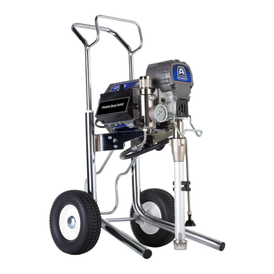
Page 8: Component Identification
Component Identification Component Identification Hi-Boy Models M Drain Tube ON/OFF Switch Suction Tube Pressure Control Pump 2-Finger Trigger Fluid Outlet Prime Valve Hanger Tip Guard Filter Spray Tip Finger Guard / TSO Fill Point Pail Hook Airless Hose Model/Serial Tag (Not shown, located Power Cord on bottom of unit.) Trigger Lock... -
Page 9: Grounding
Grounding Grounding Do not place pail on a non-conductive surface such as paper or cardboard which interrupts grounding continuity. The equipment must be grounded to reduce the risk of static sparking and electric shock. An electric or static spark can cause fumes to ignite or explode. An improper ground can cause electric shock. -
Page 10: Pressure Relief Procedure
Pressure Relief Procedure Pressure Relief Procedure Engage the trigger lock. Follow the Pressure Relief Procedure whenever you see this symbol. ti29455a This equipment stays pressurized until Turn pressure control to lowest setting. pressure is manually relieved. To help Disengage the trigger lock. prevent serious injury from pressurized fluid, such as skin injection, splashed fluid and moving parts, follow the Pressure... -
Page 11: Trigger Lock
Pressure Relief Procedure Trigger Lock Put drain tube in a pail. Turn prime valve down. Leave prime valve in down (drain) position until you are ready to spray Always engage the trigger lock when sprayer again. is stopped to prevent the gun from being triggered accidentally by hand or if dropped or bumped. -
Page 12: Setup
Setup Setup Use wrenches to tighten securely. Engage trigger lock. When unpacking sprayer for the first time or after long term storage perform setup procedure. When first setup is performed remove shipping plug from fluid outlet. Connect airless hose to fluid outlet. Use ti29455a wrenches to tighten securely. - Page 13 Setup When unpacking sprayer for the first Make certain ON/OFF switch is OFF. time remove packaging materials from inlet strainer. After long term storage check inlet strainer for clogs and debris. ti24638b Fill throat packing nut with TSO to prevent premature packing wear. Do this daily or each time you spray.
- Page 14 Setup 10. Turn prime valve down. 15. Turn prime valve horizontal. Disengage trigger lock. ti29641a 11. Place fluid intake with drain tube in grounded metal pail partially filled with flushing fluid. See Grounding, page 9. NOTE: New sprayers are shipped with storage fluid that must be flushed out with mineral spirits prior to using the sprayer.
-
Page 15: Startup
Startup Startup Place fluid intake in paint pail. Place drain tube in waste pail. Turn pressure control 1/2 turn to start motor. Allow paint to circulate through sprayer until paint flows out the drain tube. Perform Pressure Relief Procedure, page 10. Turn pressure control to lowest pressure. - Page 16 Startup Hold gun against grounded metal waste pail. Trigger gun at least 1 minute until paint appears. High-pressure spray is able to inject toxins into the body and cause serious bodily injury. Do not stop leaks with hand or rag. Inspect Airless Hose and hose connections for leaks.
-
Page 17: Operation
Operation Operation Spray Tip Installation Screw assembly onto gun. Tighten. To avoid serious injury from skin injection do not put your hand in front of the spray tip when installing or removing the spray tip and tip guard. Perform Pressure Relief Procedure, page 10. -
Page 18: Clear Tip Clog
Operation Clear Tip Clog Hold gun perpendicular, 10-12 in. (25-30 cm) from surface. Spray back and forth; overlap by 50%. To avoid injury, never point gun at your hand or into a rag! In the event that particles or debris clog the spray tip, this sprayer is designed with a reversible spray tip that quickly and easily clears the particles without disassembling the... -
Page 19: Digital Display
Operation Digital Display Press and hold display button to change pressure units (psi, bar, or MPa). Some models are equipped with a digital display. This section explains how to use this feature. Pressure Display 1. Perform Pressure Relief ti29542a Procedure, page 10. Plug sprayer into grounded outlet. - Page 20 Operation Sprayer model number is displayed To erase last error code, press and hold followed by Data Point 1 which is the unit display button. power on time in hours. Press display button again to display Data Point 4. The software revision is displayed.
-
Page 21: Cleanup
Operation Cleanup Place fluid intake in flushing fluid. Use water for water base paint and mineral spirits for oil-based paint. Place drain tube in waste pail. Perform Pressure Relief Procedure, page 10. Remove tip guard and Spray Tip. For additional information, see separate gun manual. - Page 22 Operation Raise fluid intake above flushing fluid. 13. Remove filter from gun and sprayer if installed. Clean and inspect. Install filter. See separate gun manual. ti29545a 14. If flushing with water, flush again with mineral spirits or Pump Conditioner to leave a protective coating to prevent freezing or corrosion.
-
Page 23: Maintenance
Maintenance Maintenance Routine maintenance is important to ensure proper operation of your sprayer. Maintenance includes performing routine actions which keep your sprayer in operation and prevents trouble in the future. Activity Interval Inspect/clean sprayer filter, fluid inlet strainer, and gun Daily or each time you spray filter. -
Page 24: Troubleshooting
Troubleshooting Troubleshooting Mechanical/Fluid Flow Follow Pressure Relief Procedure, Check all possible problems and causes page 10, before checking or repairing. before disassembling the unit. What to Check What to Do If check is OK, go to next When check is not OK, Problem check refer to this column... - Page 25 Troubleshooting What to Check What to Do If check is OK, go to next When check is not OK, Problem check refer to this column Pump output is low Pump rod damage. Repair pump. See pump manual. Low stall pressure. Turn pressure knob fully clockwise.
- Page 26 Troubleshooting What to Check What to Do If check is OK, go to next When check is not OK, Problem check refer to this column Pump is difficult to prime Air in pump or hose. Check and tighten all fluid connections.
-
Page 27: Electrical
Troubleshooting Electrical View digital display or remove control box cover to view control board status light. To determine which code (or any Symptom: Sprayer does not run, stops other code besides voltage supply) refer running, or will not shut off. to the control board status light. - Page 28 Troubleshooting Problem What to Check How to check Check transducer or transducer Sprayer does not run at all Make sure there is no pressure in the system (see Pressure Relief connections Procedure, page 10). Check fluid Display shows E=02 path for clogs, such as clogged filter. Use airless paint spray hose with no metal braid.
- Page 29 Troubleshooting Problem What to Check How to check Sprayer does not run at all Control is commanding motor to run 1.Remove pump and try to run but motor shaft does not rotate. sprayer. If motor runs, check for Possibly locked rotor condition, an locked or frozen pump or drive train.
- Page 30 Troubleshooting Problem What to Check How to check 6.Connect the Red and Black leads from the motor to an Ohm meter. Rotate the motor while checking for opens. If an open is found replace the motor. BLACK (-) RED (+) YELLOW 1-3 ohms ti24723a...
- Page 31 Troubleshooting Problem What to Check How to check 8.Use an Ohm meter to check motor for shorts. Connect (–) meter lead to motor case. Move the (+) meter lead to each motor wire. Meter should read open on all wires. GROUND BLACK YELLOW...
- Page 32 Troubleshooting Problem What to Check How to check Basic electrical problems Motor leads are securely fastened Replace loose terminals; crimp to and properly mated leads. Be sure terminal are firmly connected. Clean circuit board terminals. Securely reconnect leads. For loose motor brush lead Tighten terminal screws.
- Page 33 Troubleshooting Sprayer Will Not Run (See following page for steps) Remove Control box cover. Turn sprayer ON. Observe control board status light on See Step 1. Do you control board (see page 27). have over 100 VAC (220 VAC for 230v units)? No Light Once Normal Operation...
- Page 34 Troubleshooting Step 3: Check motor thermal switch. Unplug yellow wires. Meter should read continuity. NOTE: Motor should be cool during reading. BEEP Yellow Thermistor Wires to motor ti24729a Step 4: Disconnect potentiometer. Plug power cord in and turn switch ON. Control Board ti24730a...
- Page 35 Troubleshooting Sprayer Will Not Shut Off Remove control box cover so the control board status light can be viewed Perform Pressure Relief Procedure, if available. page 10. Leave prime valve open (down) and turn ON/OFF switch OFF. Troubleshooting Procedure Plumb pressure gauge into paint hose, Mechanical problem: plug sprayer in, and turn power switch ON.
-
Page 36: Hi-Boy Sprayer
Hi-Boy Sprayer Hi-Boy Sprayer Ref. Torque 140-160 in-lb (15.8 - 18.1 N•m) 30-35 in-lb (3.4 - 4.0 N•m) Hammer tight 25-30 ft-lb (33.8 - 40.6 N•m) 3A7942A... -
Page 37: Hi-Boy Sprayer Parts List
Hi-Boy Sprayer Hi-Boy Sprayer Parts List Ref. Part Description Qty. Ref. Part Description Qty. 19Y309 TUBE, suction, intake, 107434 BEARING, thrust includes 14 116073 WASHER, thrust 17N201 GUN, spray 116074 WASHER, thrust 15D000 CLIP, drain line 116079 BEARING, thrust 63 15G026 LABEL, danger (on 118494 O-RING... -
Page 38: Control Box
Control Box Control Box Ref. Torque 140-160 in-lb (15.8 - 18.1 N•m) 20-25 in-lb (2.3 - 2.8 N•m) 37-43 ft-lb (50.2 - 58.3 N•m) 130-150 in-lb (14.7 - 16.9 N•m) 3A7942A... -
Page 39: Control Box Parts List
Control Box Control Box Parts List Ref. Part Description Qty. Ref. Part Description Qty. 15E022 SEAT, valve 117828 PACKING, o-ring 187625 HANDLE, valve, drain 111457 PACKING, o-ring 195428 BOOT, toggle 111600 PIN, grooved 239914 VALVE, drain, 277364 GASKET, seat, valve includes 5, 26 115498 SCREW, mch,... -
Page 40: Wiring Diagrams
Wiring Diagrams Wiring Diagrams 230V NOTICE Heat from inductor coil of filter board may destroy wire insulation that comes in contact with it. Exposed wires could cause shorts and component damage. Bundle and tie loose wires so none lay in contact with inductor coil on the filter board. -
Page 41: Technical Specifications
Technical Specifications Technical Specifications LP 955 Metric Sprayer Maximum fluid working pressure. 3300 psi 228 bar, 22.8 MPa Maximum Delivery 0.80 gpm 3.0 lpm Maximum Tip Size Single Gun 0.029 Two Guns 0.019 Fluid Outlet npsm 1/4 in. Cycles 570 per gallon... -
Page 42: Airlessco Standard Warranty
With the exception of any special, extended, or limited warranty published by Airlessco, Airlessco will, for a period of twelve months from the date of sale, repair or replace any part of the equipment determined by Airlessco to be defective. This warranty applies only when the equipment is installed, operated and maintained in accordance with Airlessco’s written recommendations. - Page 43 Airlessco Standard Warranty Airlessco Information For the latest information about AIRLESSCO products, visit www.airlessco.com. For patent information, see www.graco.com/patents. 3A7942A...
- Page 44 All written and visual data contained in this document reflects the latest product information available at the time of publication. Airlessco reserves the right to make changes at any time without notice. Original Instructions. This manual contains English. MM 3A7942 GRACO INC.
Need help?
Do you have a question about the LP 955 and is the answer not in the manual?
Questions and answers