
Related Manuals for AIRLESSCO LP400 ALLPRO 410E


Summary of Contents for AIRLESSCO LP400 ALLPRO 410E
- Page 1 IRLESS AINT PRAYER ERVICE / PERATION ANUAL AIRLESSCO LP400 ALLPRO 410E Form No. 001-700 APR07...
-
Page 2: Table Of Contents
Servicing Suction Assembly Packing Replacement Electrical Board Calibration Electrical Troubleshooting Replacement of Electrical Components Manufactured by: AIRLESSCO BY DUROTECH CO. 5397 N. Commerce Ave., Moorpark, CA 93021Tel: 805-523-0211 Fax: 805-523-1063 www.airlessco.com email: techsupport@airlessco.com SUBJECT TO CHANGE WITHOUT NOTICE. Copyright © 2007, All rights reserved. -
Page 3: Introduction
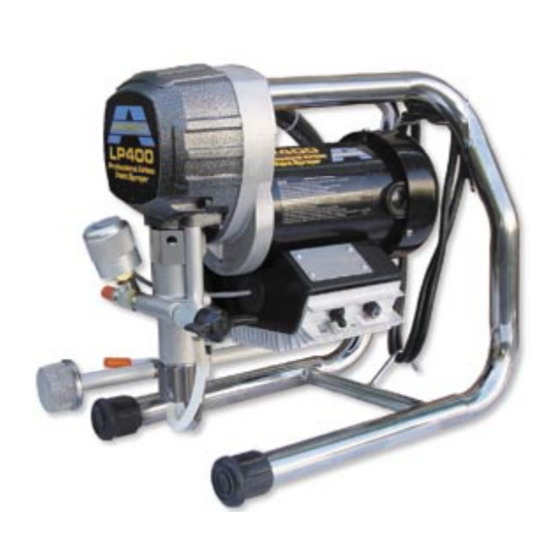
INTRODUCTION The LP400/410E delivers the durability of an Airlessco, with the simplicity of a mechanical pressure control system. It's built on a compact, well balanced triple chrome plated carry frame sturdy enough to stand on. It's powered by a dependable fan cooled, totally enclosed DC motor - no troublesome electronic controls! The heart of any contractor sprayer is the pump, and the durability of the LP pump is legendary amongst pro painters. -
Page 4: Safety Warnings
SAFETY WARNINGS HIGH PRESSURE SPRAY CAN CAUSE EXTREMELY SERIOUS INJURY. Handle as you would a loaded firearm. Follow the PRESSURE RELIEF PROCEDURE DO NOT USE HALOGENATED SOLVENTS IN THIS SYSTEM. The prime valve, and most airless guns have aluminum parts and may explode. Cleaning agents, coatings, paints or adhesives may contain halogenated hydrocarbon solvents. - Page 5 SAFETY WARNINGS ALWAYS INSPECT SPRAYING AREA HOSES • Tighten all of the fluid connections securely before each • Keep the spraying area free from obstructions. use. High pressure fluid can dislodge a loose coupling or • Make sure the spraying area has good ventilation allow high pressure spray to be emitted from the coupling to safely remove vapors and mists.
- Page 6 SAFETY WARNINGS UL RECOMMENDATION FOR MINIMUM GAUGE EXTENSION CORD AMPERAGE VOLTAGE LENGTH OF CORD IN FEET RATING RANGE 5 - 6 6 - 8 8 - 10 10 - 12 • ALWAYS use approved high pressure fittings and Always Follow Recommended Pressure replacement parts.
-
Page 7: Flushing
FLUSHING 1. New Sprayer 5. Storage Your sprayer was factory tested in an oil solution which Always relieve pressure (See pressure relief was left in the pump. Before using oil-base paint, fl ush procedure on page 10) prior to storage or when with mineral spirits only. - Page 8 HOW TO FLUSH (continued) 1. Be sure the gun safety latch is engaged and there 6. Disengage the gun safety latch and squeeze the is no spray tip in the gun. Refer to page 14 on how gun trigger. Turn the ON-OFF Toggle Switch to the to lock the safety latch and the gun's safety features.
-
Page 9: Setting Up
2. Fill the packing nut/wet cup with object being sprayed, as instructed in the safety warning section of this manual. 5 drops of Airlessco Throat Seal Oil (TSO). See (Figure 6). 5. Flush the sprayer FIGURE 6... -
Page 10: Starting Up
STARTING UP STARTING UP 2. Prepare the material 1. Learn the functions of the controls. PRIME/PRESSURE (PR) RELIEF VALVE is used to a. Prepare the material according to the material prime pump and to relieve pressure from gun, hose and tip. manufacturer's recommendations. - Page 11 Clean the tip & gun as recommended on page 11 for Always point the gun toward the ground Airlessco 008 gun or separate gun instruction manual for or into a waste container when checking all others.
-
Page 12: Pressure Relief Procedure
Service Center. DAILY MAINTENANCE 1. Keep the displacement pump packing nut/wet cup lubricated with Airlessco TSO (Throat Seal Oil) at all times. The TSO helps protect the rod and the packings. 2. Inspect the packing nut daily. Your pump has a patented Triple Life Packing System. Packing life will be extended a minimum of three times if the following "Packing Adjustment"... -
Page 13: Spray Gun Operation
SPRAY GUN OPERATION SPRAY GUN Attach spray gun to airless unit and tighten fittings securely. Set the gun safety latch. (Also may be called gun safety lock, or trigger lock) * The gun safety latch should always be set when the gun is not being triggered. - Page 14 AIRLESS SPRAY GUN TROUBLESHOOTING Problem Cause Correction Coarse Spray, Spotty Pattern Pressure setting low Increase pressure setting Irratic spray gun/hand motion Use a steady, parallel pass Excessive Overspray (Fogging) Pressure setting high Reduce pressure setting Paint over thinned/reduced/cut Use less thinner/water/reducer Spray Pattern Excessively Wide Incorrect fan width selection Select narrower fan width tip*...
-
Page 15: Spray Tip Selection
SPRAY TIP SELECTION Spray tip selection is based on paint viscosity, paint type, and job needs. For light viscosities (thin paints), use a smaller tip; for heavier viscosities (thicker paints), use a larger tip size. Spray tip size is based on how many gallons of paint per minute can be sprayed through the tip. Do not use a tip larger than the maximum pump flow rate or capacity the sprayer can accommodate. - Page 16 NEW Wide Tips ► Double orifice design for lower pressure spraying when you need a smoother finish on interior trim, cabinetry, shutters, and doors. Fan Width Orifice Size Inches (mm) .012 .014 102-152 212 214 152-203 312 314 8-10 203-254 412 414...
-
Page 17: Electric Motor Maintenance
NOTE: For longer life, new brushes (Part No. 331-778) need to have a run in period. After changing brushes, set up the machine for spraying. Use a bucket of water and Airlessco Pump Conditioner mixture, a 50 foot x 1/4" airless hose, airless gun with 0.017 tip on unit, turn the Prime/PR Control Valve to the Prime position and turn the unit on. -
Page 18: Field Troubleshooting
FIELD TROUBLESHOOTING PROBLEM CAUSE SOLUTION Unit doesn't prime †Airleak due to: • Loose Suction Nut • Tighten Suction Nut • Worn O-Rings • Replace O-Ring (106-011) on suction seat, & O-Ring (106-020) below suction seat • Hole in Suction Hose •... - Page 19 GEAR AND PUMP ASSEMBLY FIGURE 12 Do not operate machine without cover guard in place. Part Number Description 331-234 Cover 331-046 Bearing 331-038 Crosshead Assembly 331-406 Gear Crank 331-047 Bearing 331-040 Gearbox Casting * 100-381 Bolt Soc Hd (2) 100-380 Shoulder Bolt (2) 331-088 Retaining Ring...
-
Page 20: Servicing The Fluid Pump
SERVICING THE FLUID PUMP NOTE: Check everything in the Troublshooting Chart before disassembling the Fluid Pump. Fluid Pump Removal - Refer to Figure 11 1. Follow the Pressure Relief Procedure page 10. 2. Flush the material you are spraying out of the machine. 3. - Page 21 7. Tighten the packing nut counter clockwise until resistance is felt against the Belleville Springs, then go 3/4 of a turn more. Put five drops of Airlessco Throat Seal Oil into the packing nut. 8. Run the machine at full pressure for several minutes. Release the pressure by following the Pressure Relief Procedure &...
-
Page 22: Servicing Piston Rod, Outlet Valve
Servicing the Piston Rod - Outlet Valve DISASSEMBLY OF THE OUTLET VALVE REFER TO FIGURE 13 1. Disconnect the Fluid Pump. Piston 2. Place piston holder (Item 1) in a vise. Slide piston into the holder & lock in place with a 3/8” dowel (Item2). 3. - Page 23 Packing Replacement Procedures Replacement Instructions: Fluid Pump Removal - Refer to Figure 11 8. Take three Belleville Springs (331-025) & slide over the top of the piston in the following order: 1. Follow steps 1-9 on page 16 under Removal * First spring, curve facing down procedures.
-
Page 24: Packing Replacement
Packing Replacement Procedures ( Continued) FIGURE 15 FIGURE 16... - Page 25 FRAME ASSEMBLY Part Number 331-401 FIGURE 17 Item Part # Description Item Part # Description 331-234 Cover 111-037 Screw (4) 331-143 Frame 100-382 Screw (2) 119-048 Screw (4) 100-028 Plug 1/4 NPT 331-490 .6 HPDC Motor 331-048 Rubber Boot (2) 331-212 100-180 Prime P/R Valve...
- Page 26 SUCTION ASSEMBLIES Part Number 331-238 FIGURE 18 Item Part Description Number 331-217 Inlet Strainer 331-135 Spring Clip 331-290 Suction Hose Ass’y (Inc. strainer) 331-425 Bypass Hose 111-016 Nylon Tie 331-231 Bypass Hose Ass’y 331-090R Fitting 331-035 Suction Elbow 331-034 Suction Nut 106-020 O-Ring PTFE...
- Page 27 TROUBLESHOOTING Machine does not start Refer to Figure 19 CAUSE STEPS STEP 1: After making sure that the machine is plugged into the wall, verify that the Control Settings on-off switch is in the ON position and that the pressure control knob is turned all the way to the right (clockwise for maximum pressure).
-
Page 28: Electrical Board Calibration
1. Attach a 50', 1/4" airless hose, airless gun with 0.017 tip and a 5000 psi glycerin filled pressure gauge to the pump. 2. Place the suction tube into a bucket of Airlessco Pump Conditioner and water. 3. Turn prime/pressure relief valve to the prime (open) position and prime fluid pump. - Page 29 ELECTRICAL SYSTEM FIGURE 19 Item Part # Description 331-168 Electrical Power Cord 331-185 Strain Relief 331-138 Screw 331-312 Fuse Holder 331-256 Fuse 15A Slow Blow 331-311 Toggle Switch 331-490 Motor .6HP 90VCD 331-749 Pressure Control Assembly 331-725 Pressure Control Switch...
- Page 30 NOTES...
- Page 31 NOTES...
- Page 32 AIRLESSCO BY DUROTECH CO. 5397 N. Commerce Ave., Moorpark, CA 93021 Tel: 805-523-0211 Fax: 805-523-1063 www.airlessco.com eMail: techsupport@airlessco.com SUBJECT TO CHANGE WITHOUT NOTICE. Copyright © 2007 Airlessco by Durotech Co. All rights reserved.
Need help?
Do you have a question about the LP400 ALLPRO 410E and is the answer not in the manual?
Questions and answers