Advertisement
INSTALLATION AND OPERATION MANUAL
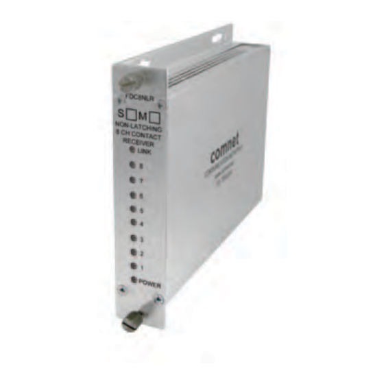
FDC8NLR(M,S)1
8-ChANNEL CoNtACt CLoSuRE NoN-LAtChING RECEIVER
the FDC8NLR contact closure receiver provides transmission of up to eight
independent contact closures over one optical fiber. Microprocessor-based
logic sends the contact information in packets that are ordered and encoded,
ensuring extremely robust transmission. Packets that are garbled, packets out of
sequence, and transmission bit errors will not cause random changes of state on
the contact relays.
the solid-state non-latching relays default to a normally open state in the event of
power loss or loss of optical signal. See Figure 3 on Page 3 for contact settings.
Each module incorporates power and individual status indicating LED's for
monitoring confirmation of contact closure of each of the eight channels. See
Figure 5 on Page 3 for an explanation of the LED indicators.
these units are interchangeable between stand-alone or card mount
configurations. See Figure A on Page 4 for mounting instructions.
See Figures 1 – 5 for complete installation information.
INS_FDC8NLR_REV–
10/08/10
PAGE 1
Advertisement
Table of Contents

Related Manuals for Comnet FDC8NLR1


Summary of Contents for Comnet FDC8NLR1
- Page 1 INSTALLATION AND OPERATION MANUAL FDC8NLR(M,S)1 8-ChANNEL CoNtACt CLoSuRE NoN-LAtChING RECEIVER the FDC8NLR contact closure receiver provides transmission of up to eight independent contact closures over one optical fiber. Microprocessor-based logic sends the contact information in packets that are ordered and encoded, ensuring extremely robust transmission.
- Page 2 INSTALLATION AND OPERATION MANUAL FDC8NLR FIGURE 1 – FDC8NLR RECEIVER MULTIMODE OR SINGLE MODE OPTICAL FIBER BLACK BLACK WITH WHITE STRIPE Power Supply: Surface Mount: 8–15 VDC @ 150mA Rack Mount: From Rack FIGURE 2 – FDC8NLR RECEIVER FRONT PANEL REAR PANEL NOTE: Remove Electrical Connector for Rack Mount Units NOTE: Remove Earth Ground screw, nuts and lock washers for Rack Mount Units...
- Page 3 INSTALLATION AND OPERATION MANUAL FDC8NLR FIGURE 3 – TYPICAL RELAY SETTINGS OUTPUT (–) RELAy OUTPUT (+) OUTPUT (–) OUTPUT (+) OUTPUT (–) OUTPUT (+) OUTPUT (–) OUTPUT (+) OUTPUT (–) OUTPUT (+) OUTPUT (–) OUTPUT (+) OUTPUT (–) OUTPUT (+) OUTPUT (–) OUTPUT (+) FIGURE 4 –...
- Page 4 8 TURNbERRy PARK ROAD | GILDERSOME | MORLEy | LEEDS, UK LS27 7LE T: +44 (0)113 307 6400 | F: +44 (0)113 253 7462 | INFO-EUROPE@COMNET.NET INS_FDC8NLR_REV– 10/08/10 © 2011 Communications Networks Corporation. All Rights Reserved. “ComNet” and the “ComNet Logo” are registered trademarks of Communication Networks, LLC. PAGE 4...
Need help?
Do you have a question about the FDC8NLR1 and is the answer not in the manual?
Questions and answers