
Related Manuals for Woodward MSLC 9907-004


Summary of Contents for Woodward MSLC 9907-004
- Page 1 Product Manual 02022 (Revision B) Original Instructions MSLC Master Synchronizer and Load Control 9907-004 (4-Wire Wye) 9907-005 (3-Wire Delta, 120 V) 9907-006 (3-Wire Delta, 240 V) Installation and Operation Manual...
- Page 2 Woodward reserves the right to update any portion of this publication at any time. Information provided by Woodward is believed to be correct and reliable. However, no responsibility is assumed by Woodward unless otherwise expressly undertaken.
-
Page 3: Table Of Contents
Calibration Check ....................44 Synchronizer Adjustment ..................44 Phase Matching Synchronizer ................45 Voltage Matching Adjustment ................49 Load Control Adjustment ..................50 Process Control Adjustment ................. 53 Conclusion of Setup Procedures ................54 Woodward... - Page 4 10. S ..............81 HAPTER ERVICE PTIONS Product Service Options ..................81 Woodward Factory Servicing Options ..............82 Returning Equipment for Repair ................82 Replacement Parts ....................83 Engineering Services .................... 83 How to Contact Woodward ................... 84 ...
- Page 5 Figure 5-1. Synchronizer Block Diagram .............. 56 Figure 5-2. Synchronizer Wiring Diagram ............57 Figure 8-1. Process Control Block Diagram ............66 Figure 9-1. Typical LON Setup ................67 Table 10-1. System Troubleshooting ..............80 Woodward...
-
Page 6: Warnings And Notices
Start-up On- and off-highway Mobile Applications: Unless Woodward's control functions as the supervisory control, customer should install a system totally independent of the prime mover control system that... -
Page 7: Electrostatic Discharge Awareness
Do not touch the components or conductors on a printed circuit board with your hands or with conductive devices. To prevent damage to electronic components caused by improper handling, read and observe the precautions in Woodward manual 82715 , Guide for Handling and Protection of Electronic Controls, Printed Circuit Boards, and Modules. - Page 8 MSLC Master Synchronizer and Load Control Manual 02022 Woodward...
-
Page 9: Chapter 1. General Information
Application The MSLC is a microprocessor-based overall plant load control designed for use in a system with Woodward DSLC™ (Digital Synchronizer and Load Control) controls on each generator to provide utility synchronizing, paralleling, loading, and unloading of a three-phase generating system. -
Page 10: Load Control
4–20 mA (1–5 Vdc) remote process reference. The output of the process control, like the import/export control, is the percentage of rated load setpoint to the individual generators in isochronous load sharing. Woodward... -
Page 11: Var/Pf Control
Chapter 9 provides a troubleshooting guide. Due to the extensive built-in diagnostics, MSLC installation may be tested and verified quickly. Chapter 10 describes how to return the control to Woodward in the event of damage or failure of an internal component. ... -
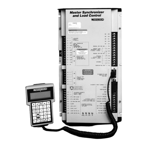
Page 12: Figure 1-1A. Mslc (Wye Version Shown)
MSLC Master Synchronizer and Load Control Manual 02022 Figure 1-1a. MSLC (wye version shown) Woodward... -
Page 13: Figure 1-1B. Mslc Dimensions (Wye Version Shown)
Manual 02022 MSLC Master Synchronizer and Load Control Figure 1-1b. MSLC Dimensions (wye version shown) Woodward... -
Page 14: Figure 1-2. Hand Held Programmer
MSLC Master Synchronizer and Load Control Manual 02022 Figure 1-2. Hand Held Programmer Woodward... -
Page 15: Figure 1-3. Typical Wiring Connections
Manual 02022 MSLC Master Synchronizer and Load Control Figure 1-3. Typical Wiring Connections (9907-004 for 120/240 V wye switchgear configuration) Woodward... -
Page 16: Figure 1-4. Typical Wiring Connections
MSLC Master Synchronizer and Load Control Manual 02022 Figure 1-4. Typical Wiring Connections (9907-005 for open delta, 120 V switchgear configuration) Woodward... -
Page 17: Figure 1-5. Typical Wiring Connections
Manual 02022 MSLC Master Synchronizer and Load Control Figure 1-5. Typical Wiring Connections (9907-006 for open delta, 240 V switchgear configuration) Woodward... -
Page 18: Chapter 2. Installation
Electrical Connections This section covers typical wiring connections, as shown in Figure 1-3. For other applications, contact Woodward Governor Company for assistance. Connect the terminals as shown in Figure 1-3. When making the connections, observe the following: ... -
Page 19: Shielded Wiring
50 mm (2 inches). The other end of the shields must be left open and insulated from any other conductor. Do NOT run shielded signal wires along with other wires carrying large currents. See Woodward application note 50532, Interference Control in Electronic Governing Systems for more information. -
Page 20: Local Bus Potential Transformers
150 Vac RMS on inputs labeled 120V, or 300 Vac RMS on inputs labeled 240V respectively. Local bus phase rotation must correspond to the phase rotation of the utility or tie bus for proper synchronization. Woodward... -
Page 21: Utility Potential Transformers
The discrete outputs are the relay driver output commands from the MSLC. Each optically isolated discrete output is designed as a low-side driver capable of sinking a maximum of 200 mA. The use of drivers allows the user to supply relays of a contact rating appropriate for the particular application. Woodward... -
Page 22: Figure 3-1. Temporary Wiring For Transformer Phase Correction
Make connections to terminals 24–27 as shown in Figure 1-3. Alarm Relay Make the alarm relay connection as shown in Figure 1-3 to terminal 28 of the MSLC. Alarm conditions are selectable by the user (see tables in Chapter 3). Woodward... -
Page 23: Discrete Inputs
Ramp Pause Contact Connect the load ramp pause switch contact to terminal 51. When closed, this contact will hold any load ramp in progress at its current setting until the contact is opened. Woodward... -
Page 24: Local Area Network
The following requirements must be met: 1. Use only recommended shielded twisted pair cabling for the LonWorks network. Correct cable is available from Woodward, Belden, or other suppliers providing an equivalent cable. Belden... -
Page 25: Figure 3-2. Mslc In A Parallel Bus/Utility Parallel Application
Manual 02022 MSLC Master Synchronizer and Load Control Figure 3-2. MSLC in a Parallel Bus/Utility Parallel Application Woodward... -
Page 26: Process Control Input
Check for shield faults by measuring the resistance from control terminals to chassis. If a resistance less than infinite is obtained, remove the connections from each terminal one at a time until the resistance is infinite. Check the last line removed to locate the fault. Woodward... -
Page 27: Chapter 3. Calibration And Adjustments
When the self-test is complete, the screen will be blank. Press the ID key to display the part number and revision level of the software in the control. Refer to this number and revision level in any correspondence with Woodward Governor Company. -
Page 28: Figure 4-1. Hand Held Programmer Functions
“Turtle Down” or “Rabbit Down” keys to decrease the value. The “Rabbit Up” and “Rabbit Down” keys will make the rate of change faster than the “Turtle Up” and “Turtle Down” keys. This is useful during initial setup where a value may need to be changed significantly. Woodward... -
Page 29: Menu 1-Synchronizer
10.00 0.10 9. C.B. Close Hold Time 10.0 10. Close Attempts 11. Reclose Delay 1000 12. Sync Reclose Alarm Disabled Enabled Disabled 13. Sync Timeout 1000 14. Sync Timeout Alarm Disabled Enabled Disabled 15. Auto Re-Synchronize Disabled Enabled Disabled Woodward... -
Page 30: Menu 2-Load Control
PT x CT ratio < 10 PT x CT ratio < 10 Kilowatts 10 < PT x CT < 75 000 10 < PT x CT < 37 500 Megawatts PT x CT > 75 000 PT x CT > 37 500 Woodward... -
Page 31: Menu 3-Process Control
9. Network Service Pin 10. Revert Status Lock In Last Hardware Lock In Last 11. Net Dropout Time 0.50 50.00 5.00 12. Utility Breaker Open Logic Direct Indirect Indirect * NOTE: Use kV only when Primary Voltage is greater than 33 kV. Woodward... -
Page 32: Menu 6-Calibration
18. Slip Frequency –1.0 Slow 5.0 Fast Hz (Fast or Slow) 19. System Load –100 +120 20. System PF 0.5 Lagging 0.5 Leading Lagging, Leading * NOTE: Active Power is positive when exporting power, and negative when importing power. Woodward... -
Page 33: Menu 8-Control Status Monitor
Contact Open/Closed 8. Ramp Pause Contact Open/Closed 9. Setpoint Raise Contact Open/Closed 10. Setpoint Lower Contact Open/Closed 11. Raise Voltage Contact Open/Closed 12. Lower Voltage Contact Open/Closed 13. Test Key 14. Breaker Close Relay Energized/De-energized 15. Utility Breaker Open Energized/De-energized Woodward... -
Page 34: Menu 0-Diagnostics
Sync NV Update Lost Invalid Resp Alloc Invalid Domain Read Past EndOfMsg Write Past EndOfMsg Addr Table Index Incomplete Msg Update On Output NV No Msg Avail Illegal Send Unknown PDU Invalid NV Index Divide by Zero Invalid Appl Error Woodward... -
Page 35: Menu (Set Point) Descriptions
If the slip frequency reference is negative (slow) the local bus voltage may not be greater than the utility voltage. This ensures that the initial reactive power flow is in the same direction as the initial real power flow. Woodward... - Page 36 Imp/Exp Stability (integral term) compensates for lags in the load control loop. It prevents slow hunting and controls damping (overshoot or undershoot) after a load disturbance. Imp/Exp Derivative adjusts the rate of change in the load command during a load transient. Woodward...
- Page 37 15. Raise Load Rate is the rate at which the control changes the load reference when the set point raise switch is activated. 16. Lower Load Rate is the rate at which the control changes the load reference when the set point lower switch is activated. Woodward...
- Page 38 31. Gen Load Switch 2 PU sets the percentage system load level at which load switch #2 discrete output is activated. 32. Gen Load Switch 2 DO sets the percentage system load level at which load switch #2 discrete output is de-activated. Woodward...
- Page 39 15. Low Limit Alarm specifies if the process low limit alarm will activated (de- energize) the alarm relay. 16. Process Switches specifies if the process high and low limits will activate the high and low limit discrete outputs. Woodward...
- Page 40 VARs being absorbed/generated across the utility tie. It is recommended that the Constant Generator Power Factor control mode be used in applications where the total generator kVAR capacity is less than the kVAR load of the system. Woodward...
- Page 41 Process Action specifies if the process variable is direct or indirect acting. If the process variable increases when the associated generators' load increases, the action is direct. Conversely, if the process variable decreases when the associated generators' load increases, the action is indirect. Woodward...
- Page 42 This is referred to as the “Hardware Loop” (displayed as Loop 4 in menu 0 of the DSLC hand held programmer). Woodward...
- Page 43 INDIRECT If set for Indirect, the Breaker Open Command Output will be normally energized, and will de-energize to issue a utility breaker open command. The Utility Breaker Open command is issued during normal operation in Utility Unload mode. Woodward...
- Page 44 CT Phase A displays the sensed phase A current. When currents are applied to the control, adjust the displayed value to equal the actual phase A current. NOTE: This must be calibrated as part of the installation on the actual switchboard. Woodward...
- Page 45 COMMANDS menu item if the control is set for command inputs from hardware, but a valid message is being seen on the network. The DI Commands monitor shows only the status of the USE_DS command inputs. The USE_CBAUX and USE_PS, USE_RR status is not indicated by this display. Woodward...
- Page 46 10. Phase B PF is the power factor on phase B of the utility bus. 11. Phase C is the voltage on phase C of the utility bus. 12. Phase C is the current on phase C of the utility bus. Woodward...
- Page 47 PF Reference is the internal reference setpoint of the MSLC. Synchronizer Timeout is the status of the alarm for exceeding the synchronizer timeout interval. Sync Reclose Limit is the status of the alarm for exceeding the synchronizer close attempts limit. Woodward...
- Page 48 12. Lower Voltage is the status of the voltage lower contact input. 13. Test Key must be set to 49 to allow closing of discrete outputs for test purposes. In addition, all discrete inputs must be open to allow testing of discrete outputs. Woodward...
- Page 49 Transmit Errors is the number of CRC (Cyclic Redundancy Check) errors detected during packet reception. These may be due to collisions or noise on the transceiver input. Pressing the “.” key will retrieve the current number of transmission error statistics. Woodward...
- Page 50 16. Hardware Loop is a TRUE/FALSE indication which, when true, indicates a network command input failure has occurred, causing the MSLC control to lock into the current hardware input operating commands. See Chapter 3, “Menu 5 Configuration” section, for more details on network command operations. Woodward...
-
Page 51: Prestart Setup Procedure
MSLC will be controlling. Prestart Load Limits and Switches Setup Set all load limits and switches according to the descriptions above and the specific plant application. Document these values in the worksheet in Appendix A for future reference and installations. Woodward... -
Page 52: Mslc Adjustments
To assist in setup and adjustments, you can monitor synchronizer mode of operation on Menu 8 and Synchronizer Mode and Slip Frequency and Synchroscope values on Menu 7. Woodward... -
Page 53: Phase Matching Synchronizer
Set the Slip Frequency Ref set point to 0.0 Hz to select phase matching. Close the synchronizer Check Mode switch. With utility and bus active, adjust the synchronizer Gain set point for stable control of the utility frequency as indicated by the synchroscope's holding steady at zero phase. Woodward... - Page 54 Repeat steps 5 and 6 if necessary to get the desired performance. Verify synchronizer performance under all expected operating conditions, such as synchronizing at higher or lower speeds. Woodward...
- Page 55 If the synchronizer action is too slow, increase Sync Gain by a factor of two. If increasing Sync Gain results in unstable operation, reduce the value by at least one-half and proceed to step 6. Otherwise, repeat steps 4 and 5. Woodward...
- Page 56 Set the Sync Timeout to the maximum number of seconds the synchronizer should attempt to achieve synchronization. Set to 0 for no timeout. If an alarm is desired when the Sync Timeout interval expires, set the Sync Timeout Alarm set point to Enabled. Woodward...
-
Page 57: Voltage Matching Adjustment
If the voltage cycles through the window without settling into it, the voltage adjusting potentiometer on the DSLC controls may need to be adjusted. See the DSLC manual. Set the synchronizer to “OFF”, manually lower the local bus voltage until it is approximately 5% lower than the utility voltage. Woodward... -
Page 58: Load Control Adjustment
Temporarily issue a lower set point command, and then a raise set point command. Verify that the load command changes appropriately and that the engines in isochronous load sharing respond appropriately. Woodward... - Page 59 0% or 100%. Temporarily issue a lower set point command, and then a raise set point command. Verify that the load command changes appropriately and that the engines in isochronous load sharing respond appropriately. This completes the import/export setup. Woodward...
- Page 60 If it is desired that the Alarm output will also de-energize the alarm relay when load reaches the Low Limit PU, set the Low Limit Alarm set point to Enabled. The alarm will be automatically cleared when load increases to above the Low Limit DO switch point. Woodward...
-
Page 61: Process Control Adjustment
Set the Process High Limit PU and DO set points to the desired values. The Process High Limit PU set point must be set to limit the range of the process reference even if the alarm will not be used. Woodward... -
Page 62: Conclusion Of Setup Procedures
Failure to save the set points before removing power from the control causes them to revert to the previously saved settings. Disconnect the Hand Held Programmer from the control. Close the cover over J1 and re-tighten the retaining screw. Woodward... -
Page 63: Chapter 4. Synchronizer Description
Permissive mode enables the synch-check function for proper synchronization, but synchronizer operation does not affect the engine's speed or generator voltage. If phase, frequency, and voltage are within proper limits, the synchronizer issues the breaker closure command. Woodward... -
Page 64: Figure 5-1. Synchronizer Block Diagram
MSLC Master Synchronizer and Load Control Manual 02022 Figure 5-1. Synchronizer Block Diagram Woodward... -
Page 65: Figure 5-2. Synchronizer Wiring Diagram
Manual 02022 MSLC Master Synchronizer and Load Control Figure 5-2. Synchronizer Wiring Diagram (120 V wye configuration shown) Woodward... - Page 66 This will ensure that the initial power flow is out of or into the plant. The slip frequency method of paralleling is selected when the slip frequency reference is set to a non-zero value. Woodward...
- Page 67 “OFF” and then back to “RUN” before the control will again attempt synchronization. An alarm is provided which if enabled will energize the alarm relay driver, terminal 24, if the a sync timeout occurs. The sync timeout function is disabled by setting it to zero. Woodward...
-
Page 68: Chapter 5. Real Power Control
Reactive Power Q = ( S - P ) Power Factor pf = Phase Angle Frequency f = where T is the sampling period. The sampling period is derived from the zero crossings of the A phase voltage signal. Woodward... -
Page 69: Load Sensor Hardware Description
DSLC controls will control to this percentage of their rated loads, and the MSLC will adjust this system load up or down to achieve the proper import/export level. For safety, the MSLC is limited to controlling generators between 0% and 100%. Woodward... -
Page 70: Process Control Mode
It will then issue a local generator bus breaker open command. This will transfer the plant load back to the utility power grid. Woodward... - Page 71 The local plant unload is accomplished by switching to base load mode and supplying a continuous set point lower command. The ramp pause command will pause all ramps in any mode. Woodward...
-
Page 72: Var/Pf Control
MSLC controls only those DSLC controls which are in isochronous load sharing. Any DSLC controls which are in base load mode will control the reactive power on their associated generators in accordance with their own internal reference and chosen mode of VAR/PF control. Woodward... -
Page 73: Chapter 7. Process Control
The MSLC system load command is obeyed only by the associated DSLC controls which are in isochronous load sharing. Base load or process control mode will ignore the MSLC load command signal and maintain its set base load reference. Woodward... -
Page 74: Figure 8-1. Process Control Block Diagram
MSLC Master Synchronizer and Load Control Manual 02022 Figure 8-1. Process Control Block Diagram Woodward... -
Page 75: Chapter 8. Echelon Lonworks™ Network
LonWorks-compatible devices through a custom installation. This chapter provides information on network specifications and the optional capabilities of the MSLC. Contact the Woodward Governor Company for full information on optional devices to take advantage of these features. Figure 9-1. Typical LON Setup... -
Page 76: Remote Metering
+1.0). Power factor is further encoded such that 1.0 represents 0.0 lagging power factor, +1.0 represents 0.0 leading power factor, and 0.0 represents a power factor of 1.0. (Note: power factor across the utility tie is available at a 200 ms rate.) Woodward... -
Page 77: Commands To Dslc Controls
(does not have 20-40 Vdc applied). A bit value of “1” indicates that the specified input is active. The bit representation is: 0—Synchronizer Check Mode 1—Synchronizer Permissive Mode 2—Synchronizer Run Mode 3—Circuit Breaker Auxiliary Contact 4—Utility Unload 5—Import/Export Control 6—Process Control 7—Ramp Pause 8—Set Point Raise 9—Set Point Lower 10—Voltage Raise Woodward... - Page 78 The load control state is updated once per second. The value representation is: 0—Offline 1—Baseload 2—Baseload Lower 3—Baseload Raise 4—Baseload Remote 5—Utility Unload 6—Process Ramp 7—Process Control 8—Process Lower 9—Process Raise 10—Process Remote 11—Import/Export Ramp 12—Import/Export Control 13—Import/Export Lower 14—Import/Export Raise 15—Import/Export Remote Woodward...
-
Page 79: Remote Control Inputs
The hardware discrete inputs must not be used when the network input is used. Changing any hardware discrete input causes the MSLC to look at all the hardware discrete inputs. Woodward... -
Page 80: Specifications
Network Bus Length: 500 m (+20 to +85 °C) typical 150 m (+40 to +85 °C) typical Maximum Stub Length: 300 mm (+40 to +85 °C) 600 mm (0 to +70 °C) Network Termination: Required at both ends of the network Woodward... -
Page 81: Chapter 9. Troubleshooting
Failure to display this message indicates either the control or Hand Held Programmer has failed. Replace the MSLC or Hand Held Programmer. Select the Diagnostics menu by pressing “0”. The Self Test Result should display a value of 49. If any other value is displayed, replace the control. Woodward... - Page 82 Vdc). Adjust the Process Cal set point for 20.0 ± 0.1 mA. Be sure to save the calibration information by pressing the “SAVE” key on the Hand Held Programmer. Repeat the above process input tests to verify correct calibration over the input range. Woodward...
- Page 83 This section tests the operation and calibrates the Utility Potential Inputs. Both the high voltage (240 Vac) and low voltage (120 Vac) inputs may be optionally tested. Calibration of the input must be done for the appropriate voltage used in service. Woodward...
-
Page 84: Lonworks Network
Select Menu 6 Synchroscope set point. With the voltage input to the Bus and Utility Phase A inputs connected in parallel, adjust the Synchroscope value to 0.0 ± 0.1 degrees. LonWorks Network Menu 0 (Diagnostics Menu), beginning with item 3, contains information to aid in verifying operation and troubleshooting of network operation. Woodward... - Page 85 The number of errors from message collisions is a function of the number of messages presented to the network. More than five or ten errors per second indicates the network function should be checked. Woodward...
- Page 86 If no custom installation has been done and sufficient errors are occurring to cause load sharing problems, contact Woodward Governor Company. Missed Messages is the number of times the network processor received more messages at one time than it could process.
- Page 87 If problems still exist, you may disconnect or replace a MSLC or other device attached to the network to investigate its effect on the network. If a custom installation has been done, it will be necessary to use the installation network management tool to properly install a replacement device on the network. Woodward...
- Page 88 Menu 5 to ensure that they are linearly across their the same. entire range (Menus 6 & 7) *—NOTE 1: Installing PROMs backwards will result in the destruction of the chips. PROMs that have been powered up while installed backwards will need to be replaced. Woodward...
-
Page 89: Chapter 10. Service Options
Woodward systems and components for the retrofits and overhauls, long term service contracts, emergency repairs, etc. You can locate your nearest Woodward distributor, AISF, RER, or RTR on our website at: www.woodward.com/directory... -
Page 90: Woodward Factory Servicing Options
Flat Rate Remanufacture: Flat Rate Remanufacture is very similar to the Flat Rate Repair option with the exception that the unit will be returned to you in “like- new” condition and carry with it the full standard Woodward product warranty (Woodward Product and Service Warranty 5-01-1205). This option is applicable to mechanical products only. -
Page 91: Replacement Parts
Engineering Services Woodward offers various Engineering Services for our products. For these services, you can contact us by telephone, by email, or through the Woodward website. Technical Support ... -
Page 92: How To Contact Woodward
MSLC Master Synchronizer and Load Control Manual 02022 How to Contact Woodward For assistance, call one of the following Woodward facilities to obtain the address and phone number of the facility nearest your location where you will be able to get information and service. -
Page 93: Mslc Setup Work Sheet
Auto Re-Synchronize Enabled | Disabled Load Control Menu 2 Imp/Exp Control Gain __________ Imp/Exp Stability __________Seconds Imp/Exp Derivative __________Seconds Imp/Exp Deadband __________% Load Input Filter __________Hertz Import/Export Droop __________% Rated Load __________kW Import/Export Level __________kW Import/Export 4 mA __________kW Woodward... -
Page 94: Process Control Menu 3
__________% Gen Load Switch 1 DO __________% Gen Load Switch 2 PU __________% Gen Load Switch 2 DO __________% Process Control Menu 3 Process Control Gain __________ Process Stability __________Seconds Process Derivative __________Seconds Process Deadband __________mA Process Droop __________% Woodward... -
Page 95: Var/Pf Control Menu 4
PF Reference 0.0 lag | 0.0 lead Const-Gen-PF-Ref __________ PF Deadband __________ Voltage Low Limit __________V, kV Voltage Low Alarm Enabled | Disabled Voltage High Limit __________V, kV Voltage High Alarm Enabled | Disabled Voltage Switches Enabled | Disabled Woodward... -
Page 96: Configuration Menu 5
Line-to-Line | Line-to-Neutral | Volts | Kilovolts System Frequency 50 Hz | 60 Hz Process Action Direct | Indirect Network Address __________ Network Service Pin __________ Revert Status Hardware|Lock In Last Net Dropout Time _________seconds Util Breaker Open Logic Direct | Indirect Woodward... -
Page 97: Mslc Specifications
12 to 40 Vdc Burden 10 mA nominal Relay Driver Outputs Voltage 12 to 40 Vdc Current 200 mA sink (max) Analog Inputs Current 4 to 20 mA Voltage 1 to 5 Vdc 243 current mode Resistance 10 k voltage mode Woodward... -
Page 98: Environmental Specifications
Test Methods US MIL-STD-810C, Method 516.2, Shock Procedure I, Figure 516.2-2, basic design test Procedure II, transit drop test Procedure V, bench handling test Electromagnetic Susceptibility Test Method ANSI/IEEE C37.90.2 Electrostatic Discharge 6000 Volts Electrical Transients Test Method ANSI C37.90.1-1989 Woodward... -
Page 99: Mslc Menu Summary
MSLC Menu Summary 1—Synchronizer 4—VAR/PF Control 8—Control Status Monitor Sync Gain VAR/PF Control Mode Synchronizer Mode Sync Stability VAR/PF Gain Load Control Mode Slip Frequency Ref VAR/PF Stability Import/Export Ref Slip Window Rated kVARS Process Reference Max Phase Window kVAR Reference Load Command Output Voltage Matching PF Reference... - Page 100 Email and Website—www.woodward.com Woodward has company-owned plants, subsidiaries, and branches, as well as authorized distributors and other authorized service and sales facilities throughout the world. Complete address / phone / fax / email information for all locations is available on our website.
Need help?
Do you have a question about the MSLC 9907-004 and is the answer not in the manual?
Questions and answers