Advertisement
Quick Links
Tsunami® MP-10100-BSU&SUA / MP-10100L-BSU&SUA
Quick Installation Guide
IMPORTANT!
For regulatory information and latest product updates, including the firmware and
the MIBs, please visit Proxim's support site at http://support.proxim.com.
The device must be installed by a trained professional who is familiar with Radio
Frequency planning issues and the regulatory limits.
The installation procedure is explained by taking connectorized device as an
example. Follow the same procedure for the integrated antenna device as well.
Introduction
®
Proxim's Tsunami
MP-10000 & 10000L Series leverage the advantages of Orthogonal
Frequency Division Multiplexing (OFDM), Multiple-Input and Multiple-Output (MIMO) radio
innovations and Proxim's proprietary Wireless Outdoor Router Protocol (WORP
wireless solutions exceeding 4G speed requirements with up to 867 Mbps data rate. With high
®
capacity and high power radio, the Tsunami
MP-10000 & 10000L Series is an ideal solution for
everything from last mile Broadband Wireless Access (BWA) to Wireless Video Surveillance for
extended coverage.
Products Covered
Model
Description
®
MP-10100-BSU
Outdoor Tsunami
Base Station with 2 N-Type connectors, 867 Mbps
data rate and 2x2 MIMO radio operating in 4.900 to 5.925 GHz
frequency band.
®
MP-10100-SUA
Outdoor Tsunami
Subscriber Unit with 2 N-Type connectors, 867 Mbps
data rate and 2x2 MIMO radio operating in 4.900 to 5.925 GHz
frequency band.
®
MP-10100L-BSU
Outdoor Tsunami
Base Station Lite with 2 N-Type connectors, 400 Mbps
data rate and 2x2 MIMO radio operating in 4.900 to 5.925 GHz
frequency band.
®
MP-10100L-SUA
Outdoor Tsunami
Subscriber Unit Lite with 2 N-Type connectors, 400
Mbps data rate and 2x2 MIMO radio operating in 4.900 to 5.925 GHz
frequency band.
Package Contents
Each shipment includes the items listed in the following table. Please verify that you have
received all the parts in the shipment, prior to the installation.
What's in the Kit
Image
MP-10100-BSU /
MP-10100-SUA /
MP-10100L-BSU /
MP-10100L-SUA
Power Injector with Country
specific Power Cord
WD - US and EU power cords
US - US power cord
RJ11 Beeper Dongle
Grounding Kit
Connector Weather Proofing
Kit (2 sets)
Mounting Kit and Hardware
®
WORP Driving the Internet of Things
P/N 765-00247 Version 2.4
1
Copyrights © 2020 Proxim Wireless
What's in the Kit
RSSI Light Pipe
Comes with MP-10100(L)-BSU devices only
Quick Installation Guide
Device Overview
®
) to provide
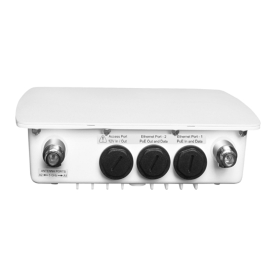
Figure 1: MP-10100-BSU/SUA or MP-10100L-BSU/SUA
The features of the device are as follows:
Features
Ethernet Port 1
•
PoE IN and Data
•
Debugging and Management
Ethernet Port 2
•
Manageable PoE OUT and Data (Default Data only)
Access Port
•
Antenna Alignment
•
12 V DC Power IN/OUT
Antenna Ports (A1, A2) in case
•
A provision to connect external antennas
of connectorized device
Grounding Points
•
A provision to ground the device
Weatherproofing RJ45 Connections
The following steps explain how to weatherproof the RJ45 connections:
Figure 2: Weatherproofing RJ45 Connections
1. Use an outdoor rated CAT5e cable with a straight-through terminated on both ends.
2. Slide the Flat Washer (A) onto the Connector Body (B) and screw the Connector Body (B)
into the Ethernet port hole and torque to 10 Lbf-in (12 Kgf-cm).
3. Next slide the Sealing Nut (E) and then the Compression Ring (D) over the cable end.
4. Place and press the two piece Compression Washer Assembly (C) onto the cable in front of
the Compression Ring (D) and Sealing Nut (E), then slide the Compression Ring (D) over
the Compression Washer (C). Do not tighten the Sealing Nut (E) to the Connector Body
(B).
5. Connect the CAT5e cable by pushing the RJ45 connector through the Connector Body (B)
and into the Radio Ethernet port. The RJ45 connector should lock into the port.
6. Next slide the Sealing Nut (E) over the Compression Washer Assembly (C) and slide the
Compression Washer Assembly (C) until the Sealing Nut (E) can be screwed it onto on the
fixed end of the Connector Body (B). Torque the connection to 15 Lbf-in (17 Kgf-cm)
making sure the Compression Washer (C) is tight to the cable and Connector Body (B)
completely sealing the cable.
7. Finally, ensure the plastic caps are tight on the secondary Ethernet Port 2 and Access Port
and torqued to 9 Lbf-in (10 Kgf-cm), if those ports are unused.
WORP Driving the Internet of Things
P/N 765-00247 Version 2.4
2
Additional Weatherproofing Steps
Image
To add an additional layer of protection to the connectors against the environment, do the
following:
1. Wrap vinyl tape in a half-lapped fashion, from the weatherproof connector end and
continue wrapping down 3 inches onto the CAT5e cable.
2. Wrap a second layer of vinyl tape in the reverse direction over the first layer of tape.
3. Now, wrap a third layer of vinyl tape over the other two layers but with the adhesive side
up as this provides a sticky surface for the next layer.
4. Next, wrap a layer of the butyl mastic tape over the adhesive side of the tape, covering all
of the tape and connector.
5. Wrap vinyl tape over the butyl layer and cover the entire tape assembly.
6. Place a small zip tie over the last wrap of tape to prevent it from unwrapping over time.
For a detailed explanation of weatherproofing RJ45 connectors and RF connections, refer to
®
Tsunami
MP-10000 & 10000L Series Hardware Installation Guide and Tsunami
10000L Series Antenna Installation Guide respectively, at http://support.proxim.com.
Assemble the Mounting Hardware
1. Fix the Mounting Plate (A) onto the bottom of the device using the provided screws and
washers such that the antennas will be vertically and horizontally polarized when
mounted; also, it is recommended to partially fasten the screws with washers into all the
mounting holes, prior to final tightening of each screw. Torque the screws to
75 Lbf-in (86 Kgf-cm).
Description
2. Fix the Extension Arm (B) to the fixed Mounting Plate (A) with the provided screw, nut, and
washers. The Extension Arm (B) gives the device more possible tilt, letting you adjust for
azimuth or elevation over a larger angle.
3. Fix the Mounting Bracket (C) to the fixed Extension Arm (B) with the provided screw, nut,
and washers. Partially tighten the joints J1 and J2 to allow for alignment of the device.
4. Once satisfied with the alignment, tighten the assembled parts by applying torque
130 Lbf-in (150 Kgf-cm).
5. The last image in Figure 3 shows the fully assembled mounting hardware attached to the
device.
Note: This figure is for illustration only. Device should be mounted in square position with
connectors facing downward.
Mount the Device
1. To pole-mount the device, insert the provided bolts through Bracket (F), mate with Bracket
(C) around the pole, and secure with supplied nuts and washers torquing to
100 Lbf-in (115 Kgf-cm). The supplied screws (hex. Cap 5/16" x 80 mm long) are designed
for pole diameters from 38 to 76 mm (1.5 to 3 inches).
®
Copyrights © 2020 Proxim Wireless
P/N 765-00247 Version 2.4
®
MP-10000 &
Figure 3: Assemble the Mounting Hardware
Figure 4: Pole Mounting
®
WORP Driving the Internet of Things
3
Copyrights © 2020 Proxim Wireless
Advertisement

Related Manuals for Proxim Tsunami MP-10100-BSU


Summary of Contents for Proxim Tsunami MP-10100-BSU
- Page 1 RSSI Light Pipe following: the MIBs, please visit Proxim’s support site at http://support.proxim.com. 1. Wrap vinyl tape in a half-lapped fashion, from the weatherproof connector end and The device must be installed by a trained professional who is familiar with Radio Comes with MP-10100(L)-BSU devices only continue wrapping down 3 inches onto the CAT5e cable.
- Page 2 5. Measure ground impedance at the point where the surge protector ground wire is Ethernet cable between the network interface card in the Personal Computer and the hub, You can configure the IP address of the device by using HTTP, SNMP, PV Advanced (Proxim’s connected and not at the grounding rod.
Need help?
Do you have a question about the Tsunami MP-10100-BSU and is the answer not in the manual?
Questions and answers