
Subscribe to Our Youtube Channel
Related Manuals for Proxim Tsunami QB-8150-LNK-5-US


Summary of Contents for Proxim Tsunami QB-8150-LNK-5-US
- Page 1 Tsunami QB-8100 Series (100 Mbps / 5 Mbps Models) Installation and Management Guide...
- Page 2 GNU Lesser General Public License ("LGPL"). Please see the GPL and LGPL Web sites to view the terms of each license. To access the GPL Code and LGPL Code used in Tsunami QB-8100, visit the proxim website to get a copy of the source. The GPL Code and LGPL Code used in this device are distributed WITHOUT ANY WARRANTY and are subject to the copyrights of one or more authors.
-
Page 3: Table Of Contents
Tsunami QB-8100 Series(100 Mbps/5 Mbps Models) Installation and Management Guide Preface..............8 Overview . - Page 4 Tsunami QB-8100 Series(100 Mbps/5 Mbps Models) Installation and Management Guide Wireless Configuration ..............46 Configuring WORP Properties in End Point A Mode .
- Page 5 Tsunami QB-8100 Series(100 Mbps/5 Mbps Models) Installation and Management Guide File Management ..............131 Upgrade Firmware via HTTP .
- Page 6 Tsunami QB-8100 Series(100 Mbps/5 Mbps Models) Installation and Management Guide Tools ................171 Link Test .
- Page 7 Tsunami QB-8100 Series(100 Mbps/5 Mbps Models) Installation and Management Guide Two Units Are Unable to Communicate Wirelessly ..........190 Surge and Lightning preventive maintenance .
-
Page 8: Preface
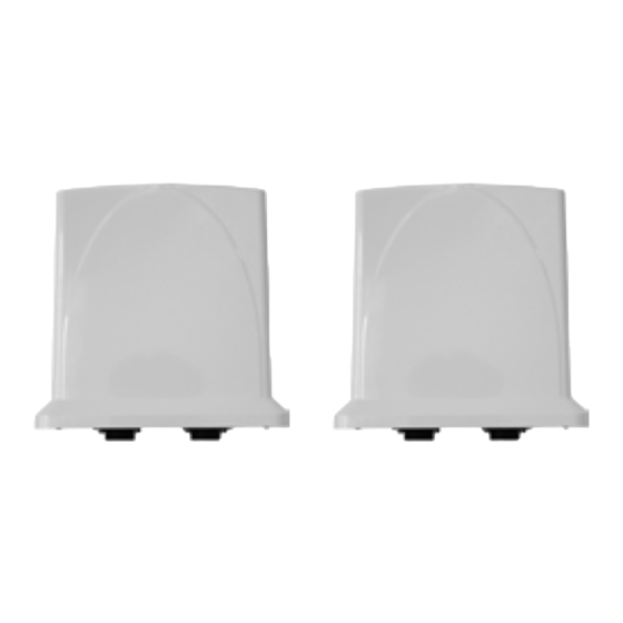
Tsunami QB-8150-LNK-100&5 -XX 16 dBi Integrated antenna Organization of this Manual This manual documents installing and managing of Tsunami QB series. Before installing and using the unit, Proxim recommends you to read the following chapters of this manual: • Chapter 1 Overview: Provides an overview of Tsunami QB-8100 as well as wireless network topologies and combinations that can be built with the unit. -
Page 9: Reference Manual
Preface The appendixes contain supplementary information, including frequency domain tables, channel frequency, and Technical Support information. If you are already familiar with this type of product, you can use the Quick Install Guide to install the unit. Reference Manual As a supplement to the Tsunami QB-8100 Series (100 Mbps/5 Mbps Models) Installation and Management Guide, the Tsunami QB-8100 Series (100 Mbps/5 Mbps Models) Reference Manual provides the following information: •... -
Page 10: Overview
Overview This chapter provides a description of the Tsunami QB-8100 Series (100 Mbps/5 Mbps Models), its functionalities, and features. It covers the following topics: • Introduction • Wireless Network Topology (Point-to-Point Link) • Multiple-Input-Multiple-Output (MIMO) • Management and Monitoring Capabilities Tsunami QB-8100 Series (100 Mbps/5 Mbps Models) Installation and Management Guide... -
Page 11: Introduction
Overview 1.1 Introduction The Tsunami QuickBridge 8100 is a wireless point-to-point device designed to provide wireless networking solutions for enterprises and small business markets. Two pre-configured bridges enable users to easily, quickly, and economically install a wireless extension between two locations, eliminating the need for costly leased line or cable alternatives. The product’s primary components are a wireless device and a Power-over-Ethernet injector. -
Page 12: Wireless Network Topology (Point-To-Point Link)
Overview 1.2 Wireless Network Topology (Point-to-Point Link) It is easy to set up a wireless point-to-point link as depicted in the following figure. Each device is set up as either an End Point A or an End Point B. Figure 1-1 Wireless Network Topology (Point-to-Point-Link) With a point-to-point link, you can set up a connection between two locations as an alternative to: •... - Page 13 Overview Figure 1-2 2x2 MIMO Tsunami QB-8100 Series (100 Mbps/5 Mbps Models) Installation and Management Guide...
-
Page 14: Management And Monitoring Capabilities
7. RFC-3414.mib (SNMP-USER-BASED-SM-MIB) The PXM MIB files are available on the Proxim Web site. You must compile one or more of these MIB files into your SNMP program’s database before you manage your device using SNMP. See the documentation that came with your SNMP manager for instructions about how to compile MIBs. - Page 15 For all other modes of connection, you will need the IP address of the device to use the Web Interface, SNMP, or the CLI via telnet. CAUTION! For Regulatory Information and latest product updates, including firmware and the MIBs, Proxim recommends visiting the Proxim Support site at http://support.proxim.com. IMPORTANT! This user guide discusses installing the device and managing it using the Web interface only.
-
Page 16: Installation And Initialization
Installation and Initialization This chapter describes the steps required to install and mount the QuickBridge 8100 Series units. If you are already familiar with this type of product, refer to the Tsunami QB-8100 Quick Installation Guide for streamlined installation procedures. This chapter covers the following topics: •... -
Page 17: Hardware Overview
The unit is designed to be mounted to a pole of 1.25” - 3” diameter (not included) using the supplied pole mount bracket accessories (P/N 909-00001). An optional universal wall mounting bracket is also available from Proxim (P/N 77537); this kit is designed to mount directly to a flat surface such as a roof, wall, or under an eave. -
Page 18: Serial Connection
Installation and Initialization 2.1.2 Serial Connection The serial connection is made with an RJ11 to DB9 connector (also referred to as a “dongle”). Connect the RJ11 end to the unit and connect the serial (DB9) end to your PC to align the antenna and to enter CLI commands. See the following figure: Figure 2-2 Serial Components The connections are as follows:... - Page 19 Installation and Initialization What’s in the Kit Image Power Injector & Power Cord Connector Weather Proofing Grounding Kit Pole Mounting Kit and Hardware The mounting kit includes the following: Quantity Component Name Image 2 ea. M6-16 Screw 2 ea. M6 Spring Washer 2 ea.
-
Page 20: Installation Procedure
CAUTION! There are no user-serviceable parts inside. All services must be performed by qualified personnel. CAUTION! For Regulatory Information and latest product updates, including firmware and the MIBs, Proxim recommends visiting the Proxim Support site at http://support.proxim.com NOTE: Equipment is to be used with, and powered by, the power injector provided with the product package or by a power injector that meets the following requirements: –... - Page 21 To make optimal use of the device, you must find a suitable location to install the hardware. The range of the radio device largely depends upon the position of the antenna. Proxim recommends you do a site survey, observing the following requirements, before mounting the hardware.
- Page 22 Installation and Initialization 1. Slide the lock nut (3) and sealing cap (2) over the bare end of a Cat5 ethernet cable (1) as shown in figure below: Cat 5 cable with bare end Lock nut and sealing cap Lock nut and sealing cap with the Cat 5 cable 2.
- Page 23 NOTE: Do not over tighten the screws at this stage, as the unit may need adjustment to obtain good signal strength. An optional universal wall mounting kit bracket is also available from Proxim (P/N 77537); this kit is designed to mount the unit directly to a flat surface such as a roof, wall, or under an eave.
- Page 24 2. Connect the other end of the Cat5 cable to the “LAN+DC” port on the power injector. NOTE: Proxim recommends to use the supplied PoE injector. Figure 2-4 PoE Injector WARNING: Connect network devices only into the “LAN”...
- Page 25 Installation and Initialization Figure 2-5 Grounding the Unit Step 9: Power on the Unit Plug in the power cord into a power outlet after having connected the Power Injector and the Radio device using Cat5 cable. There is no ON/OFF switch on the unit. To disconnect power, unplug the RJ45 connector from the “LAN+DC” port on the power injector.
-
Page 26: Initialization
Installation and Initialization 2.4 Initialization Connecting to the device requires either: A direct connection with a serial RS-232 cable. • • A direct connection with an Ethernet cable or a network connection. Connecting with the Ethernet cable allows you to use of the Web Interface and SNMP in addition to the CLI. Connecting with a serial connection allows you to configure and manage the device with the CLI. -
Page 27: Modifying The Ip Address
Installation and Initialization Figure 2-7 Scan List NOTE: If your computer has more than one network adapter installed, it prompts you to select the adapter for the ScanTool before the Scan List appears. If prompted, select the ethernet adapter and click OK. You can change your adapter setting whenever necessary by clicking Select Adapter on the Scan List screen. -
Page 28: Logging In To The Web Interface
Installation and Initialization 2.4.3.1 Assigning the IP Address Manually 1. Select the IP Address Type as Static and then enter the appropriate IP Address, Subnet Mask, and the Gateway IP Address parameters. 2. Enter the SNMP Read/Write password in the Read/Write Password field. By default, it is public. 3. -
Page 29: System Summary
Installation and Initialization • If you are unable to log into the configuration pages by using default user name and password, please check with the administrator or follow Forced Reload procedures. For security purposes, it is recommended to change Password from the default “public” immediately to restrict •... -
Page 30: Reboot Button
Installation and Initialization In some cases, upon successful COMMIT operation, a message “Please Reboot to take effect” appears as follows: 2.5.3 REBOOT Button Reboot operation is required for any change in the key parameters to take effect. For example, settings such as configuring the Radio Mode, IP Address, and Network Mode need reboot to take effect. - Page 31 Installation and Initialization NOTES: • It is always mandatory to commit the changes before REBOOT, otherwise the changes will not take effect. • The System Summary can be viewed by clicking HOME. • The Event Log can be cleared by clicking Clear Event Log and can be refreshed by clicking Refresh. An error message appears when a parameter is configured with inappropriate value.
-
Page 32: Factory Default Configuration
Installation and Initialization 2.6 Factory Default Configuration Parameter Default Network Mode Bridge Routing Disabled WORP Network Name MY_NETWORK Password public IP Address Assignment Type Static IP Address 169.254.128.132 Subnet Mask 255.255.255.0 Registration Timeout Network Secret public SNMP Management Interface Enabled Telnet Management Interface Enabled HTTP Management Interface... -
Page 33: Basic Configuration
Basic Configuration This chapter provides an overview of the basic configuration settings of Tsunami QB-8100 (100 Mbps/5 Mbps Models). It covers the following topics: • Country and Related Settings • Dynamic Frequency Selection (DFS) • Transmit Power Control • Pairing the End Points or setting up a QB Link •... -
Page 34: Country And Related Settings
Basic Configuration 3.1 Country and Related Settings The unit’s Advanced Configuration window provides a frequency domain field that automatically provides the allowed bandwidth and frequencies for the selected country. Units sold in the United States are pre-configured to scan and display only the outdoor frequencies permitted by the FCC. No other country can be configured. -
Page 35: Transmit Power Control
Basic Configuration If ACS is disabled, during initialization, the device selects the Preferred Channel to be the operational channel. If ACS is enabled, during initialization, the device scans all the channels in the configured frequency domain and selects the channel with the best RSSI to be the operational channel. -
Page 36: Virtual Local Area Networks (Vlans)
Basic Configuration First configure one End Point as End Point A and the other End Point as End Point B. The list of parameters that must be configured for linking of End Point A and End Point B are: Network Name •... -
Page 37: Basic Configuration Information
Basic Configuration 3.7 Basic Configuration Information The BASIC CONFIGURATION Page in the Web-based Configuration Interface provides a one-place access to a minimum set of configuration parameters to quickly set up a QuickBridge Point-to-Point link. Figure 3-1: Basic Configuration See the following table for Basic Configuration parameters and their descriptions: Parameter Description System Name... - Page 38 Basic Configuration Parameter Description Frequency Domain It specifies the country of operation, permitted frequency bands and regulatory rules for that country/domain. Upon choosing a frequency domain, the Dynamic Frequency Selection (DFS) and Automatic Transmit Power Control (ATPC) features are enabled automatically if the selected country and band has a regulatory domain that requires it.
- Page 39 Basic Configuration Parameter Description Active Channel This will display the current active channel on which wireless interface is operating. If you have enabled the auto channel selection option or if the device moves to a different channel because of radar detection, then this field displays the current operating channel.
-
Page 40: Advanced Configuration
Advanced Configuration This chapter provides details about the Tsunami QB-8100 unit parameters and describes the procedures to configure them using Web-based management interface. These parameters can also be configured using the other management interfaces like SNMP and CLI. The following topics are covered in this chapter: •... -
Page 41: System Configuration
Advanced Configuration 4.1 System Configuration The System screen allows you to configure the QB-8100 device as an End Point A or an End Point B, the frequency domain, and the network mode as Bridge or Routing. To configure the System 1. -
Page 42: Network Configuration
Advanced Configuration Parameter Description Maximum MTU This feature provides support for Ethernet frames with more than 1,500 bytes of payload (MTU). It can be configured with any value between 68 to 2048 bytes. By default, its value is 1500. NOTES: •... - Page 43 Advanced Configuration Figure 4-3 IP configuration in Router mode To configure the Network IP properties, click ADVANCED CONFIGURATION > Network > IP Configuration. The following screen appears: Figure 4-4 IP Configuration 1. Enter the appropriate parameters in the IP Configuration screen. See the following table that lists and describes the parameters.
- Page 44 Advanced Configuration Parameter Description Ethernet Address Type This field is applicable only if the Network mode on the System screen is configured in Bridge mode. This parameter specifies whether the device network parameters are to be configured through DHCP or to be assigned statically. Select Dynamic to configure the device as a Dynamic Host Configuration Protocol (DHCP) client.
-
Page 45: Ethernet Properties Configuration
Advanced Configuration 4.3 Ethernet Properties Configuration In the Ethernet Interface Properties screen, you can configure the Ethernet transmission properties. The recommended settings are Auto for TxMode And Speed. The device supports a single ethernet interface Ethernet 1. To configure the Ethernet Interface 1. -
Page 46: Wireless Configuration
Advanced Configuration Parameter Description TxMode And Speed This parameter allows the user to select the speed and mode based on the requirement for the corresponding interface. NOTE: • Auto: Selects the best transmission mode available when both sides are set to Auto. •... - Page 47 Advanced Configuration Figure 4-6 Wireless Interface WORP 2. Enter the appropriate parameters in the WORP Configuration screen. See the following table for the descriptions of the parameters. 3. Click OK. Tsunami QB-8100 Series (100 Mbps/5 Mbps Models) Installation and Management Guide...
- Page 48 Advanced Configuration Parameter Description Mode Specifies the radio mode in which the device is configured. Network Name It is the name given to a network so that an End Point A and an End Point B can mutually authenticate. End Point B can register to End Point A only if it has the same Network Name.
- Page 49 Advanced Configuration Parameter Description Auto Multi Frame Bursting Select Enable or Disable from Auto Multi Frame Bursting drop-down box. By default, Auto Multi Frame Bursting is enabled. NOTE: Auto Multi Frame Bursting is enabled only if Multi Frame Bursting is Enabled.
- Page 50 Advanced Configuration Parameter Description Bandwidth Limit Type This parameter specifies the action performed when the traffic utilization exceeds the configured input/output limits. Policing: When the traffic utilization reaches the configured limit, the excess traffic will be discarded. Shaping: When the traffic utilization reaches the configured limit, the excess traffic will be buffered and sent at the rate specified in the Output Bandwidth Limit.
-
Page 51: Configuring Worp Properties In End Point B Mode
Advanced Configuration 4.4.2 Configuring WORP Properties in End Point B Mode When the device is in End Point B mode, only End Point B-related configuration settings are displayed. Refer to Configuring WORP Properties in End Point A Mode. Parameter Description Mode System Name given to the End Point A (Refer to Basic... - Page 52 Advanced Configuration Figure 4-7 Wireless interface properties 2. Enter the appropriate parameters. See the following table that lists the parameters and their descriptions. 3. Click OK. NOTES: • If World/Russia frequency domain is selected, establishing WORP link might take longer time because the End Point B has to scan relatively more number of channels.
- Page 53 Advanced Configuration Parameter Descriptions Auto Channel Selection (ACS) Enable or disable the Auto Channel Selection for wireless interface. If ACS is enabled on the End Point A, it scans all the channels and selects the best channel at the startup. If ACS is enabled on the End Point B, End Point B continuously scans all the channels till it connects to an End Point A.
- Page 54 Advanced Configuration Parameter Descriptions Satellite Density Satellite Density setting helps achieve maximum bandwidth in a wireless network. It influences the receive sensitivity of the radio interface and improves operation in environments with high noise level. Reducing the sensitivity of the device enables unwanted “noise” to be filtered out (it disappears under the threshold).
- Page 55 Advanced Configuration Parameter Descriptions With Transmit Power Control (TPC), you can adjust the output power of the device to a lower level. This is performed to reduce interference with the neighboring devices. It can be helpful when higher gain antenna is used without violating the maximum radiated output power for a country or regulatory domain.
-
Page 56: Blacklist Information
Advanced Configuration 4.4.4 Blacklist Information This section displays information regarding various blacklisted channels. It consists of the following parameters. NOTE: Click COMMIT for the changes to take effect. Parameter Description Channel Number The channel number indicates the channel that is blacklisted. - Page 57 Advanced Configuration Figure 4-8 MIMO Properties 2. Enter the appropriate parameters on the MIMO Properties screen. See the following table that lists the parameters and their descriptions. 3. Click OK. NOTE: When you modify MIMO parameters and click COMMIT, it may result in brief interruption of service. Parameter Description Frequency Extension...
-
Page 58: Dfs
Advanced Configuration Parameter Description Guard Interval Possible values for Guard interval are 800 nSec and 400 nSec. 400 nSec is valid only for 40 MHz channel bandwidth. Data Streams MIMO radio uses multiple antennas for transmitting and receiving the data. These data streams specify the number of data streams over the air transmitted or received in parallel. - Page 59 Advanced Configuration If ACS is disabled, during initialization, the device selects the Preferred Channel to be the operational channel. If ACS is enabled, during initialization, the device scans all the channels in the configured frequency domain and selects the channel with the best RSSI to be the operational channel.
- Page 60 Advanced Configuration 3. During its operation, the End Point B scans for radar continuously and after detecting the radar, it sends a message to the End Point A indicating radar detection on that current channel and blacklists that channel for Non Occupancy Period (NOP).
-
Page 61: Ddrs
Advanced Configuration See the following DFS parameter configurations table that lists the parameters and their descriptions Parameter Description Channel Wait Time End Point B after selecting the best channel from its End Point A-scan list, scans for the RADAR for a period of 60 seconds in that particular channel. - Page 62 Advanced Configuration 4.4.8.1 DDRS Configuration To configure DDRS, 1. Click ADVANCED CONFIGURATION > Wireless > Interface 1 > DDRS. The DDRS Configuration screen appears as shown below: Figure 4-11 DDRS Configuration The DDRS Configuration table holds the DDRS parameter configurations. 2.
- Page 63 Advanced Configuration Parameter Description DDRS Max Data Rate This parameter specifies the maximum data rate that is selected during DDRS Algorithm. By default, 130Mbps is selected. NOTE: Algorithm will select the transmission rate between DDRS Default Data Rate and DDRS Max Data Rate configuration. Rate Incr.
- Page 64 Advanced Configuration Table 4-1 Data Rates to Rate Index Mapping Table Rate Data Rates (Mbps) Index 5 MHz Channel 10 MHz Channel 20 MHz Channel 40 MHz Channel Bandwidth Bandwidth (for Bandwidth (for Bandwidth (for Full GI-800ns) Full GI-800ns) Full GI-800ns) Longer Higher Longer...
-
Page 65: Security Configuration
Advanced Configuration 4.5 Security Configuration 4.5.1 Setting Up Wireless Security In Wireless Security page, you can configure security mechanisms used to secure the communication link between End Point A and End Point B. By default, a security profile (WORP Security) is preconfigured with the default configuration for WORP security. - Page 66 Advanced Configuration 4.5.1.1 Creating a New Security Profile To create a new security profile 1. Click ADVANCED CONFIGURATION > Security > Wireless Security. 2. Click Add in the Wireless Security Configuration screen to create a new entry. The Wireless Security Add Row screen is displayed as shown below.
- Page 67 Advanced Configuration Sample Security Profile Configuration End Point A End Point B Profile Name Encryption Type AES-CCM AES-CCM Key 1 1234567890abcdef1234567890abcdef 1234567890abcdef1234567890abcdef (32 Hexadecimal digits) (32 Hexadecimal digits) publicpublic1234 publicpublic1234 (16 ASCII Characters) (16 ASCII Characters) Network Secret public public Entry status Enable Enable...
-
Page 68: Configuring The Radius Server Profile (End Point A Only)
Advanced Configuration 4.5.1.2 Modifying a Security Profile To edit the parameters of the existing security profiles 1. Click ADVANCED CONFIGURATION > Security > Wireless Security. 2. Click Edit. The Wireless Security Edit Row page appears. 3. Edit the parameters and click OK. 4. -
Page 69: Configuring The Mac Acl (End Point A Only)
Advanced Configuration Parameter Description Profile Name Specifies the profile name. Max Retransmissions Specifies the maximum retransmissions allowed. Message Response Time Specifies the message response time. Re Authentication Period Specifies the Re Authentication Period. Entry status Displays the Radius profile as Enable. Server Type This is a read only parameter and displays the server type. - Page 70 Advanced Configuration Figure 4-15 MAC Access Control 2. Select the Operation Type as either Allow or Deny. NOTE: Based on the Operation Type, the user can allow or deny the association of the MAC ACL profile to an End Point B. 3.
-
Page 71: Quality Of Service (Qos) Configuration
Advanced Configuration 4.6 Quality of Service (QoS) Configuration The Quality of Service (QoS) feature is based on the 802.16 standard and defines the classes, service flows, and packet identification rules for specific types of traffic. 4.6.1 QoS Concepts and Definitions The software supports QoS provisioning from the End Point A only. - Page 72 Advanced Configuration a. TCP/UDP Source Port Range (5060-5061, 10000-20000) b. IP Protocol List (17 = UDP) 6. Cisco VoIP DL a. TCP/UDP Destination Port Range (16,000-33,000) b. IP Protocol List (17 = UDP) 7. Vonage VoIP DL a. TCP/UDP Destination Port Range (5060-5061, 10000-20000) b.
- Page 73 Advanced Configuration • Service Flow Direction – Downlink (DL: traffic from End Point A to End Point B); Uplink (UL: traffic from End Point B to End Point A) Maximum sustained data rate (or Maximum Information Rate, MIR) – specified in units of 1 Kbps from 8 Kbps up to •...
- Page 74 Advanced Configuration Initialization State = Active d. Maximum Sustained Data Rate = 2 Mbps e. Minimum Reserved Traffic Rate = 2 Mbps Maximum Latency = 20 milliseconds g. Traffic Priority = 1 Note that two different VoIP Service Flow classes for each direction of traffic have been defined (index numbers 4 to 7) which follow the ITU-T standard nomenclatures: G.711 refers to a type of audio companding and encoding that produces a 64 Kbps bitstream, suitable for all types of audio signals.
-
Page 75: Qos Configuration
Advanced Configuration – PIR: Vonage VoIP UL; PIR Priority: 1 – PIR: Cisco VoIP UL; PIR Priority: 1 b. SF class: DL-G729 20 ms VoIP rtPS – PIR: Vonage VoIP DL; PIR Priority: 1 – PIR: Cisco VoIP DL; PIR Priority: 1 5. - Page 76 Advanced Configuration 3. Add a New PIR MAC Address Entry a. Click Add to add a new entry. The following screen appears for configuring the MAC Entry Details. Figure 4-17 QoS PIR MAC Address Add Entry b. Provide the MAC Address, Mask, Comment, Entry Status details and click Add. Comment field can be used to identify when this particular entry is referred in PIR Rule/QoS Class.
- Page 77 Advanced Configuration Figure 4-19 QoS PIR IP Address Add Entry b. Provide the IP Address, Subnet Mask, Comment, Entry Status details and click Add. Comment field can be used by the user to identify when this particular entry is referred in PIR Rule/QoS Class. QoS PIR TCP/UDP Port Configuration 1.
- Page 78 Advanced Configuration Figure 4-21 QoS PIR TCP/UDP Port Add Entry b. Provide the Start Port, End Port, Entry Status details and click Add. Comment field can be used to identify when this particular entry is referred in PIR Rule/QoS Class. 4.6.2.1 QoS PIR Configuration 1.
- Page 79 Advanced Configuration Figure 4-22 QoS PIR Entries 2. Add a New PIR Rule. a. Click Add to add a new entry. The following screen appears for configuring the New PIR Entry. Figure 4-23 QoS PIR Add Entry b. Provide the PIR Name, Entry Status details and click Add. Tsunami QB-8100 Series (100 Mbps/5 Mbps Models) Installation and Management Guide...
- Page 80 Advanced Configuration PIR Rule Clarification Details 1. Click ADVANCED CONFIGURATION > QoS > PIR List and click Details for editing a particular PIR Rule. Figure 4-24 QoS PIR Edit Entry Tsunami QB-8100 Series (100 Mbps/5 Mbps Models) Installation and Management Guide...
- Page 81 Advanced Configuration Parameter Description Rule Name This parameter specifies the Name of the Packet Identification Rule (PIR) and can have a length of 1-32 characters. ToS Rule This parameter is used to enable/disable TOS rule. Enter the values for the following to specify the ToS-related configuration: ToS Low ToS High ToS Mask...
- Page 82 Advanced Configuration Adding Protocol ID a. Click Add to add a new Protocol entry. The following screen appears. Figure 4-25 QoS PIR Protocol ID b. Enter the details and click Add. For deleting an entry, click Delete for the corresponding entry in PIR Details page.
- Page 83 Advanced Configuration Figure 4-27 QoS PIR TCP/UDP Destination Port Add Entry b. All the entries present in the PIR TCP/UDP Port Entries are displayed in the TCP/UDP Port Entry Table. Select the appropriate radio button and click Add. After adding the entry for this specific PIR, it is displayed in the Existing TCP/UDP Port Entries table.
- Page 84 Advanced Configuration b. All the entries present in the PIR IP Address Entries are displayed in the IP Address Entry Table. Select the appropriate radio button and click Add. After adding the entry for this specific PIR, it is displayed in the Existing IP Address Entries table.
- Page 85 Advanced Configuration Figure 4-30 QoS PIR Source MAC address Add Entry b. All the entries present in the PIR MAC Address Entries are displayed in the MAC Address Entry Table. Select the appropriate radio button and click Add. After adding the entry for this specific PIR, it is displayed in the Existing MAC Address Entries table.
- Page 86 Advanced Configuration 4.6.2.2 QoS Service Flow Configuration (SFC) 1. Click ADVANCED CONFIGURATION > QoS > SFC List. Eight predefined SFCs are displayed in this page. This table allows the user to configure maximum of 32 entries. Service Flow Name should be unique. This SFC can be referred in the QoS Class’...
- Page 87 Advanced Configuration Figure 4-33 QoS Service Flow Add Entry 2. Specify details for the Service Flow Name, Scheduler Type, Traffic Direction, MIR, CIR, Max Latency, Tolerable Jitter, Traffic Priority, Max Messages in Burst and Entry Status. 3. Click Add. Parameter Description Service Flow Name Specifies the Name of the Service Flow.
- Page 88 Advanced Configuration Parameter Description Max Messages in Burst Specifies the maximum number of messages that can be sent in a burst. This value ranges from 1 to 16. NOTE: Reducing the number of messages impacts the throughput. Entry Status Specifies the Service Flow status. 4.6.2.3 QoS Class Configuration 1.
- Page 89 Advanced Configuration Parameter Description L2 Broadcast QoS Class This parameter specifies WORP to use this particular class for worp broadcast facility. L2 Broadcast QoS Class is valid only for Downlink Direction. QoS Class assigned to this profile should have at least one Downlink SFC. 4.
- Page 90 Advanced Configuration Parameter Description Priority Specifies priority or order of execution of PIRs during packet identification process. The PIR priority is a number that can range from 0-63, with priority 63 being executed first, and priority 0 being executed last. The PIR priority is defined within a QoS class, and can be different for the same PIR in some other QoS class.
- Page 91 Advanced Configuration Figure 4-37 QoS Class Service Flow Add Entry 3. Specify the Service Flow Name, PIR Rule Name, Priority and Entry Status and click Add to add a new entry. Adding PIR in QoS Class 1. Click on the corresponding Details provided in the Service Flow of a particular QoS Class. Maximum 8 PIR rules can be associated per SFC of an QoS Class.
- Page 92 Advanced Configuration Figure 4-38 QoS Class PIR Details 2. Click Add. The following screen appears for association of the new PIR rule in an SFC already associated in an QoS Class. Figure 4-39 QoS Class PIR Add Entry 3. Specify the PIR Rule Name, Priority and Entry Status and click Add to add a new entry. Tsunami QB-8100 Series (100 Mbps/5 Mbps Models) Installation and Management Guide...
-
Page 93: Qos Configuration For A Management Station
Advanced Configuration 4.6.2.4 QoS End Point Configuration 1. Click ADVANCED CONFIGURATION > QoS > End Point. By default, the table does not have any entry. User can configure the Wireless MAC Address of the End Point B here and associate the QoS Class need to be used for that particular End Point. - Page 94 Advanced Configuration If QoS is not configured properly, the system can become difficult to access in heavily loaded networks. One of the side effects of this misconfiguration is ping time-out, which is usually interpreted as a disconnection of the pinged node. However, with the correct QoS configuration, every node in the network can be reached at any moment.
- Page 95 Advanced Configuration c. Click Add that corresponds to Source IP Address Entries. This displays a screen for referring the Management Station’s IP Address. New Entry Table displays all the IP Address Entries of the PIR List. Select the option button corresponding to the Management Station and then click Add.
- Page 96 Advanced Configuration • Max Messages in Burst: 16 • Entry Status: Enable d. Click Add. The UL-Management SF is added to the QoS SFC List. NOTE: The input and output bandwidth limits set on the End Point A or on the End Point B are used for limiting aggregate bandwidth used by End Point B.
-
Page 97: Vlan Configuration (Bridge Mode Only)
The End Point’s Web interface • • The Command Line Interface (see “Command Line Interface” section in the Reference Manual) SNMP (Log on to Proxim support site http://support.proxim.com for MIBs) • NOTE: The VLAN parameters can be configured on selected Interface (Ethernet 1/Ethernet 2). -
Page 98: Vlan Modes
Advanced Configuration 1. System-related parameters: These parameters are applicable to the whole device. The following parameters are the System-related VLAN parameters. a. VLAN Status: Selecting the VLAN Status checkbox enables the VLAN Status on the device. To update all VLAN related parameters, VLAN status should be enabled. - Page 99 Advanced Configuration 2. Enter the parameters listed in the following table. 3. Click OK. Parameters Description Interface Displays the name of the interface. VLAN Mode Select the VLAN mode as Transparent. Click COMMIT for the changes to take effect. Once the transparent mode is set, both tagged and untagged frames are received on the interface.
- Page 100 Advanced Configuration Parameter Description Allow Untagged Select Enable or Disable for this option. Frames Enable If this option is selected, an interface in trunk mode forwards both tagged frames whose VLAN ID matches with one of the VLAN IDs of the trunk table and untagged frames.
-
Page 101: Filtering Configuration (Bridge Only)
Advanced Configuration To configure the Access Mode in the VLAN network 1. Click ADVANCED CONFIGURATION > VLAN > Ethernet. The VLAN Ethernet Configuration screen appears. Figure 4-46 VLAN operation in Access Mode 2. Enter the parameters as described in the following table. Parameter Description Interface... -
Page 102: Ethernet Protocol Filter
Advanced Configuration • Advanced Filter • TCP/UDP Port Filter • Storm Threshold Filter To configure the filtering mechanism 1. Click ADVANCED CONFIGURATION > Filtering. The Filtering screen appears. Figure 4-47 Filtering 2. Enter the appropriate parameters in the Filtering screen. See the following table that lists all the parameters and their descriptions. - Page 103 Advanced Configuration 1. Click ADVANCED CONFIGURATION > Filtering > Ethernet Protocol Filtering. The Protocol Filter screen is displayed as shown below. Figure 4-48 Protocol Filter Tsunami QB-8100 Series (100 Mbps/5 Mbps Models) Installation and Management Guide...
- Page 104 Advanced Configuration 2. Enter the appropriate parameters in the Protocol Filter screen. See the following table that lists the parameters and their descriptions. Parameter Description Filtering Control This parameter is used to configure the interface on which filtering has to be applied. By default, it is disabled. It can be configured as: Ethernet: Packets are examined on the receive path of the •...
-
Page 105: Static Mac Address Filter
Advanced Configuration b. Enter the details as described in the preceding table and click Add. Figure 4-49 Protocol Filter Add Row NOTE: • By default, the system generates 19 entries. You can Enable or Disable the default entries, but the Delete option is not applicable for all the default 19 entries. - Page 106 Advanced Configuration • To block traffic between a specific wired MAC address and a specific wireless MAC address, configure all four parameters. 4.8.2.2 Static MAC Filter Examples Consider a network that contains a wired server and three wireless clients. The MAC addresses for each unit are as follows: Wired Server: 00:40:F4:1C:DB:6A •...
- Page 107 Advanced Configuration • Wireless Mask: FF:FF:FF:FF:FF:FF Result: The unit blocks all traffic between Wireless Client 3 and the Ethernet network. 4.8.2.5 Static MAC Address Filter Configuration To configuring Static MAC Filter 1. Click ADVANCED CONFIGURATION > Filtering > Static Mac Address Filter. The Static MAC Address Filter screen is displayed as shown below.
-
Page 108: Advanced Filter
Advanced Configuration Parameter Description Wired MAC Mask Specifies the range of MAC address to which this filter is to be applied. Wireless MAC address Specifies the MAC address of the device on the wireless network that is restricted from communicating with a device in the wired network. - Page 109 Advanced Configuration Figure 4-52 Advanced Filtering 2. The following table describes the parameters present in the Advanced Filtering table. Parameter Description Name This parameter specifies the protocol name. The following filters are supported in Advanced Filtering: Deny IPX RIP • •...
-
Page 110: Tcp/Udp Port Filter
Advanced Configuration Figure 4-53 Advance Filtering- Edit Entries 1. After making the desired modifications, click OK to update the table. 2. Click Back to navigate to the previous page. Click Cancel to retain the previous entries. NOTE: Click COMMIT for the changes to take effect in the device. 4.8.4 TCP/UDP Port Filter Port-based filtering controls the user access to network services by selectively blocking TCP/UDP protocols through the device. - Page 111 Advanced Configuration Figure 4-54 TCP/UDP Port Filter 2. Enter the appropriate parameters. See the following table that lists the parameters and their descriptions. Parameter Description Filter Control This parameter is used to enable the TCP/UDP filter. By default, Disable is selected. Protocol Name This parameter specifies the TCP/UDP protocol filter name.
-
Page 112: Storm Threshold Filter
Advanced Configuration 4.8.4.1 Adding TCP/UDP Port Table Entries To add TCP/UDP Port Table entries 1. Click Add to create a new TCP/UDP port filter. The TCP/UDP Port Filter Add Row page is displayed as shown below. Figure 4-55 TCP/UDP Port Filter Add Row 2. -
Page 113: Worp Intra Cell Blocking (End Point A Only, Bridge Mode Only)
Advanced Configuration Figure 4-56 Storm Threshold Filter This table contains information about the threshold values per second of the multicast and broadcast packets that can be processed for the interface(s) present in the device. 2. Select the appropriate parameters. See the following table that lists the parameters and their descriptions. 3. -
Page 114: Dhcp Configuration
Advanced Configuration 4.9 DHCP Configuration Dynamic Host Configuration Protocol (DHCP) is a network protocol that enables a server to assign an IP address to a device from a defined range of IP addresses configured for a given network. It allows you to distribute IP addresses from a central point to various hosts and simplifies the process of configuring the IP addresses to individual hosts. - Page 115 Advanced Configuration Figure 4-58 DHCP 2. Enter the appropriate parameters in the DHCP Interface Table. See the following table that lists the parameters and their descriptions. NOTE: To enable the DHCP Server Interface, the DHCP server pool table should have at least one range configured for that interface.
- Page 116 Advanced Configuration 3. To enable DHCP Server, select Enable for DHCP Server Status. Before enabling, in interface table there should be at least one interface enabled on which the DHCP Server has to run and the DHCP server pool table should have at least one entry configured for that interface.
-
Page 117: Dhcp Relay (Routing Mode Only)
Advanced Configuration 1. Click Add in the DHCP Pool screen. The DHCP Pool Table Add Row screen is displayed as shown below. Figure 4-60 DHCP Pool Table Add Row 2. After entering the details, click Add. The entry will be updated in the DHCP pool table. 3. - Page 118 Advanced Configuration 1. Click Add in the DHCP Relay Server screen. The DHCP Relay Server Add Row screen is displayed as shown below. Figure 4-62 DHCP Relay Server Add Row 2. Enter the Server IP Address and then click Add. 3.
-
Page 119: Igmp Snooping (Bridge Mode Only)
Advanced Configuration 4.10 IGMP Snooping (Bridge Mode only) The Internet Group Management Protocol (IGMP) is a communication protocol used to manage the membership of Internet Protocol multicast groups. IGMP is used by IP hosts and adjacent multicast routers to establish multicast group memberships. -
Page 120: Igmp Snooping Configuration
Advanced Configuration NOTES: • IGMP Snooping functionality is available both in End Point A and End Point B. • QB 8100 supports only passive IGMP Snooping. • IGMP versions V1,V2 and V3 are supported. • End Point A/End Point B add maximum 64 Multicast groups in the Snooping table. 4.10.1 IGMP Snooping Configuration To configure IGMP Snooping: 1.Click ADVANCED Configuration >... -
Page 121: Routing Features Configuration
Advanced Configuration 4.11 Routing Features Configuration 4.11.1 Static Route Table (Routing Mode Only) The static routing table mechanism is available for End Point A and End Point B in routing mode only. It stores the route to various destinations on the network. When packets are to be routed, the routing table is referred to for the destination address. -
Page 122: Nat (End Point B, Routing Mode Only)
Advanced Configuration Parameter Description Entry Status This parameter is used to configure the status of the static route. Only enabled routes are considered for routing the packets. 4.11.1.1 Adding Static Route Entries To add Static Route entries 1. Click Add in the Static Route Table screen. The Static Route Table Add Row screen is displayed as shown below. Figure 4-66 Static Route Table Add Row 2. - Page 123 Advanced Configuration 2. Dynamic NAT: In dynamic mapping, the End Point B maps the private IP addresses and its transport identifiers to transport identifiers of a single Public IP address as they originate sessions to the public network. This is used only for outbound access.
- Page 124 Advanced Configuration Figure 4-68 NAT Port Bind Table Add Row To add entries in the NAT static port bind table 1. Enter the Local IP Address of the host on the Ethernet (private) side of the End Point B. 2. Select the Port Type as: TCP, UDP, or Both. 3.
-
Page 125: Rip (Routing Mode Only)
Advanced Configuration S.No. Protocol Support Applications H.323 H.323 ALG Multimedia Conferencing HTTP Port Mapping Web Browser inbound connection TFTP Port Mapping Trivial file transfer inbound connection Telnet Port Mapping Remote login inbound connection Port Mapping Chat and file transfer inbound connection AMANDA Port Mapping... - Page 126 Advanced Configuration Figure 4-69 Configuring RIP 2. Enter the appropriate parameters. See the following table that lists the parameters and their descriptions. 3. Click OK. Click COMMIT for the changes to take effect. Parameter Description Name Displays the name of the interface as Ethernet 1 or Wireless.
-
Page 127: System Management
System Management This chapter provides details about the Management screen of the Web interface and describes the procedures to effectively manage the Tsunami QB-8100 device. It covers the following topics: • System • File Management • Services: Configuring the Passwords •... -
Page 128: System
System Management 5.1 System 5.1.1 System Information This section displays the basic system information. This information further helps in viewing the device details during troubleshooting. For configuring the system information, click MANAGEMENT > System > Information. Figure 5-1 System Information Parameter Description System Up-Time... -
Page 129: Identifying The Components (Inventory Management)
System Management Parameter Description Phone Number Specifies the Phone number of the concerned person responsible for the device. Location Specifies the location of the device. GPS Longitude, GPS Latitude Specifies the GPS longitude, latitude and altitude at and GPS Altitude which the device is installed. - Page 130 System Management Figure 5-3 Licensed features Parameter Description Product Description Specifies the product description. Number of Radios Specifies the number of radios that the device is licensed to operate. Number of Ethernet Interfaces Specifies the number of Ethernet interfaces that the device is licensed to operate.
-
Page 131: File Management
System Management 5.2 File Management Using this section, you can upgrade the firmware or configuration of the device and also retrieve the log/configuration files from the device. File Management can be done using TFTP (by using an external TFTP Server) using Web, CLI or SNMP. It can also be done using the HTTP using Web Interface. -
Page 132: Upgrade Firmware Via Tftp
System Management Figure 5-5 HTTP Update-Configuration To upgrade the configuration via HTTP 1. Click Browse and locate the configuration file. Select “Flashcfg.cfg” for binary configuration file and “PXM-TBC.xml” to upgrade the Text Based Configuration file. For more information on how to upgrade the Text Based configuration file refer to Updating the device with TBC File. -
Page 133: Upgrade Configuration Via Tftp
System Management To upgrade the firmware via TFTP server: 1. Enter the TFTP Server IP Address. 2. Enter the name of the firmware file to update to the device. 3. Click Update to initiate the new firmware updation or click Update and Reboot to update and reboot with new firmware immediately. -
Page 134: Retrieve From Device
System Management Figure 5-8 Upgrade Text Based Configuration via TFTP 5.2.5 Retrieve From Device 5.2.5.1 HTTP Retrieve For retrieving a configuration file or Event log or Text based template configuration file via HTTP web interface, click MANAGEMENT > File Management > Retrieve From Device > HTTP. To retrieve files from the device via HTTP 1. - Page 135 System Management 5.2.5.2 TFTP Retrieve This option is used to retrieve files from the device to the TFTP server. The TFTP server must be running and configured in the desired directory path to copy the retrieved file. Assign a proper name to the file which may include version or location information.
-
Page 136: Services: Configuring The Passwords
System Management 5.3 Services: Configuring the Passwords SNMP version, SNMP passwords, and SNMP Trap Host Table parameters can be configured to prevent unauthorized access. Each management interface can be configured with its own password. Each of the three management interfaces (HTTP/HTTPS, Telnet/SSH, and SNMP) is arranged in tabs under the Services link of MANAGEMENT tab in the Main Left Panel. -
Page 137: Telnet/Ssh
System Management Parameter Description HTTPS Similar settings as mentioned for HTTP. The password configuration for HTTPS is same as configured for HTTP. 5.3.2 Telnet/SSH Figure 5-12 Telnet/SSH Tsunami QB-8100 Series (100 Mbps/5 Mbps Models) Installation and Management Guide... - Page 138 System Management The parameters for Telnet/SSH are described in the following table. Telnet/SSH Parameter settings Password Set a new password for the interface or interfaces to manage the device through the CLI. The same password is used for serial CLI also. Telnet Select Enable to allow the Telnet access to the device from any host.
-
Page 139: Snmp
System Management 5.3.3 SNMP Figure 5-13 SNMP The parameters for SNMP are described in the following table. SNMP Parameter settings SNMP This parameter provides the access control for the SNMP interface. Select Enable/Disable to enable or disable the SNMP access to the device from any host. Disabling the SNMP will affect the NMS/PVES access to the device. - Page 140 System Management Read Password This parameter represents the read only community name used in SNMP Protocol. It is sent along with each SNMP GET / WALK / GETNEXT / GETBULK request to allow or deny access to the device. This password should be same as read password set at the NMS or MIB browser.
- Page 141 System Management On selecting SNMP V3, the following parameters need to be configured: SNMP V3 Parameter settings Security level The supported security levels for QB-8100 is AuthNoPriv and AuthPriv. Select AuthNoPriv for Extensible Authentication or AuthPriv for both Authentication and Privacy (Encryption). Priv Protocol This field configures the type of privacy (or encryption) protocol.
-
Page 142: System Log Host Table
System Management 3. Select the entry status as Enable or Disable and click Add. All traps will be delivered to the host port number 162. The community string/ password field is not valid if the device is configured in SNMPv3 mode. NOTE: Changes to SNMP parameters require a Reboot to take effect. - Page 143 System Management Figure 5-17 SYSLOG Host Table Add Row Parameter Description IP Address Represents the IP address of the SYSLOG server. Port Represents the host port number. Default port is 514. NOTE: The user must configure the correct port number on which the syslog server is running for the Host Port parameter.
-
Page 144: Sntp
System Management 5.4 SNTP SNTP allows a network entity to communicate with time servers in the network/Internet to retrieve and synchronize the time of day information. When this feature is enabled, the system attempts to retrieve the time of day information from the configured time servers (primary or secondary);... -
Page 145: Access Control
System Management NOTE: • Provide the Primary and Secondary Server details only if the SNTP status is enabled. • For any reason, if the servers configured are not responding, the SNTP client retries every minute. 5.5 Access Control The Management Access Control feature provides the option of controlling the management interfaces only from the specified hosts. -
Page 146: Reset To Factory
System Management Figure 5-20 Management Access Table Add Row 3. Enter the IP Address of the device. 4. Select Enable or Disable for the Entry status of the device. 5. Click Add. Ensure that the IP address of the management PC that is used to manage the device is present in the table. Otherwise, you will not be able to manage the device. -
Page 147: Monitoring The System
Monitoring the System This chapter describes the procedures to monitor the Tsunami QB-8100 using the MONITOR screen of the Web interface. It covers the following topics: • Interface Statistics • WORP Statistics • Bridge • Network Layer • Radius (End Point A only) •... -
Page 148: Interface Statistics
Monitoring the System 6.1 Interface Statistics Interface Statistics provides detailed information about the data exchanged in both directions through the device interface. The statistical information include the type of interface, operational status, MAC address of the protocol, number of packets transmitted, signal information, number of collisions and errors occurred while transmitting the data. -
Page 149: Wireless Statistics
Monitoring the System Field Description This parameter displays to the largest size of the data packet received/sent on the interface. Physical Address This parameter displays the MAC address at the Ethernet protocol layer. Operational Status This parameter displays the current operational state of the interface. - Page 150 Monitoring the System Parameter Description Antenna Specifies all the antenna ports available for the product. This is based on the product option. For QB-8100, it shows A1and A2. Status Specifies the configuration status of the antenna ports. ON indicates that antenna port is enable for that chain. OFF means antenna port is disabled for that chain.
- Page 151 Monitoring the System Figure 6-2 Wireless Statistics Tsunami QB-8100 Series (100 Mbps/5 Mbps Models) Installation and Management Guide...
-
Page 152: Worp Statistics
Monitoring the System 6.2 WORP Statistics 6.2.1 General Statistics WORP General Statistics screen displays the signal information, WORP data messages, Data transmission statistics, and Registration details of all the data transmitted through the interface. To view the General Statistics, click MONITOR > WORP Statistics > Interface 1 > General Statistics. Figure 6-3 WORP General Statistics The parameters displayed in this page are described in the following table. - Page 153 Monitoring the System Field Description Avg Remote Noise Refers to the noise level with which the End Point B receives wireless frames from the End Point A. WORP Data Messages Specifies the sent or received data frames through wireless interface. Poll Data Refers to the number of polls with data messages sent (End Point A) or received (End Point B).
-
Page 154: End Point B Link Statistics (End Point A Only)
Monitoring the System Field Description Request For Service Refers to the number of requests for service messages sent (End Point B) or received (End Point A). Registration Requests Refers to the number of registration request messages sent (End Point B) or received (End Point A) on WORP interface. - Page 155 Monitoring the System Figure 6-4 End Point B Link Statistics Click Refresh, to get the updated or latest End Point B Link Statistics. The following table lists the parameters and their descriptions: Field Description End Point B Name System name of the End Point B connected. connected Mac Address MAC address of the End Point B...
-
Page 156: End Point A Link Statistics (End Point B Only)
Monitoring the System Field Description Remote Antenna Port Info Refers to the status of the remote antenna port of the End Point B. The status of the remote antenna port is shown by three different legends. For more information on the legends, refer to Local Antenna Port Info. - Page 157 Monitoring the System Figure 6-6 QoS Summary Tsunami QB-8100 Series (100 Mbps/5 Mbps Models) Installation and Management Guide...
-
Page 158: Bridge
Monitoring the System 6.3 Bridge 6.3.1 Bridge Statistics To view the Bridge Statistics, click MONITOR > Bridge > Bridge Statistics. Figure 6-7 Bridge Statistics The following table lists the parameters and their descriptions Parameter Description Description Displays the textual string containing information about the interface. -
Page 159: Learn Table
Monitoring the System Parameter Description In Unicast Packets Displays the number of subnetwork unicast packets received at the bridge interface. In Non-unicast Packets Displays the number of non-unicast (i.e., subnetwork-broadcast or subnetwork-multicast) packets received at the bridge interface. In Errors Displays the number of inbound packets that contained errors and are restricted for delivering them to a higher-layer protocol at the bridge interface. - Page 160 Monitoring the System Figure 6-8 Learn Table 2. Click Clear to delete all entries of the Learn Table. 3. Click Refresh to get the updated or latest Learn Table. Tsunami QB-8100 Series (100 Mbps/5 Mbps Models) Installation and Management Guide...
-
Page 161: Network Layer
Monitoring the System 6.4 Network Layer 6.4.1 Routing Table Routing table displays all the active routes of the network. These can be either static or dynamic (obtained through RIP). For every route created in the network, the details of that particular link or route will get updated in this table. To view the Routing Table, click MONITOR >... -
Page 162: Icmp Statistics
Monitoring the System Figure 6-10 IP ARP Table 2. Click Clear to delete all entries of the ARP Table. 3. Click Refresh to get the updated or latest ARP Table. 6.4.3 ICMP Statistics This page provides the statistical information for both received and transmitted messages by the device. The ICMP Statistics attributes can be used to monitor message traffic. -
Page 163: Rip Database
Monitoring the System The following table lists the parameters and their descriptions Field Description In Msgs/Out Msgs The number of ICMP messages that are received/transmitted by the device. In Errors/Out Errors The number of ICMP messages that the entity received/transmitted but determined as having errors. - Page 164 Monitoring the System Figure 6-12 RIP Database Tsunami QB-8100 Series (100 Mbps/5 Mbps Models) Installation and Management Guide...
-
Page 165: Radius (End Point A Only)
Monitoring the System 6.5 Radius (End Point A only) This section displays the information about the radius authentication statistics. NOTE: Radius Client Authentication Statistics are visible only on End Point A. 6.5.1 Radius Authentication Statistics This page provides information about Radius Authentication for both the primary and backup servers for each radius server profile. - Page 166 Monitoring the System Field Description Accepts Specifies the number of Radius Access Accept messages received since client startup. Rejects Specifies the number of Radius Access Reject messages received since client startup. Resp Specifies the number of Radius response packets received by the system since client startup. Mal Resp Specifies the number of malformed Radius Access Response messages received since client startup.
-
Page 167: Igmp (Bridge Mode Only)
Monitoring the System 6.6 IGMP (Bridge Mode only) Click MONITOR > IGMP > IGMP Snooping Stats. The Ethernet/Wireless Multicast List screen appears as shown below: Figure 6-14 Ethernet1 Multicast List 6.6.1 Ethernet/Wireless Multicast List: 1. The Multicast List table holds the IGMP Multicast IP and Multicast MAC address details for the Ethernet/Wireless interfaces. 2. -
Page 168: Dhcp
Monitoring the System Click MONITOR > IGMP > Router Port List. The Router Port List screen appears as shown below: Figure 6-15 Router Port List See the following table that lists the parameters and their descriptions. Parameter Description Port No This parameter represents the port number on which multicast router is attached (on which IGMP Query has been received). -
Page 169: Logs
Monitoring the System 6.8 Logs 6.8.1 Event Log The Event Log keeps track of events that occur during the operation of the device. It displays the event occurring time, event type, and the name of the error or the error message. Based on the priority, the event details are logged and can be used for any reference or troubleshooting. -
Page 170: Syslog
Monitoring the System • To delete the Event Log, click Clear Event Log. NOTE: The recent eventlogs are stored in the flash memory. 6.8.2 Syslog System log messages are generated by the system by sending requests at various instances to the system log server. Figure 6-18 System Log •... -
Page 171: Tools
Monitoring the System 6.9 Tools 6.9.1 Link Test WORP Link Test shows, in graphical form, Signal and Noise levels at which packets are received at local and remote unit. WORP link test feature is used to monitor the local/remote signal/noise/SNR details of the connected WORP link. During antenna alignment, this feature can be enabled to monitor the min/cur/max signal details. -
Page 172: Wireless Site Survey (End Point B Only)
Monitoring the System Figure 6-20 WORP Link Status Graph To stop the link test, click Explore Stop. NOTE: Link tests are performed for maximum 3 times. By default, the Link Test Status is disabled. 6.9.2 Wireless Site Survey (End Point B Only) Wireless Site Survey is done by the End Point B and scans all the available channels and channel bandwidths, and collects information about all the End Point As on only those channels/bandwidths with the given Network Name. - Page 173 Monitoring the System Figure 6-21 Wireless Site Survey Table To initialize the survey process, click Start button. This process lists all the available End Point A details. If you want to stop the site survey process, click the Stop button. Click Refresh, to get the updated or latest Wireless Site Survey Table.
-
Page 174: Procedures
Procedures This chapter provides details about the various procedures involved in the operation of the QB-8100 units through the Web, CLI, and SNMP interface. The following topics are covered in this chapter: • TFTP Server Setup • Web Interface Firmware Download •... -
Page 175: Tftp Server Setup
You can download the SolarWinds TFTP server software from the product installation CD or from http://support.proxim.com. You can also download the latest TFTP software from SolarWind’s Web site at http://www.solarwinds.net. The following instructions are prepared with an assumption that you are using the SolarWinds TFTP server software;... -
Page 176: Configuration Backup
Procedures 7.3 Configuration Backup You can back up the unit’s configuration by retrieving the configuration file. You can use this file to restore the configuration or to configure another similar unit (see Restore). You can update a configuration file through TFTP or HTTP. Configuration 7.3.1 Through TFTP 1. -
Page 177: Text Based Configuration (Tbc) File Management
Procedures 3. Fill in the following details: • File Name <configuration file name> 4. Click Update to start the file transfer. A reboot is required for the new configuration to be restored into the device. 7.5 Text Based Configuration (TBC) File Management 7.5.1 Text Based Configuration File Text Based Configuration (TBC) file is a simple text file that holds the template configurations of the device. - Page 178 Procedures Figure 7-1 HTTP Retrieve of TBC File 1. From the File Type list, select Text Based Template Config file. 2. Click Retrieve to initiate the operation and retrieve the file to the local system. 3. On clicking Retrieve, a Download window appears as shown below. To download and save the file to your local system, right click on the link HERE, then save the file to your system.
- Page 179 Procedures Figure 7-3 TFTP Retrieve of TBC File 1. Enter the TFTP Server IP address. 2. Enter the name of the file to be uploaded from the device. 3. Select the file type as Text Based Template Config. 4. To retrieve the file from the TFTP Server, Click Retrieve. The following window appears as shown below: Figure 7-4 Successful retrieve of TBC NOTE: The Text Based Template Configuration file does not exist if it is not generated from the CLI.
-
Page 180: Editing The Tbc File
The Text Based Config (TBC) file can easily be opened and edited in any standard Text-Editors like Wordpad, MS-Word, Notepadd++, Standard XML Editors. Proxim recommends XML Notepad 7 editor for editing the TBC file. You can modify any value between the double quotes(““) in the TBC file. It is recommended not to change the text •... - Page 181 Procedures Figure 7-6 Update the device with TBC File via HTTP 1. Click Browse and select the TBC file. 2. Click Update to initiate the HTTP Update operation. 3. Click Load to load the TBC file. 4. Click Update & Load to update and load with new configurations immediately. NOTES: •...
-
Page 182: Loading The Tbc File
Procedures Figure 7-7 Update the device with TBC File via TFTP 1. Select the Text Based Config option button. 2. Enter the TFTP Server IP Address. 3. Enter the name of the configuration file to be updated to the device. Click Update to initiate the TFTP update operation. -
Page 183: Soft Reset To Factory Default
Procedures NOTE: Both Commit and Reboot are required to accept the modifications done in the TBC File. Only reboot is required to reject the modifications. Loading the TBC file is allowed only once in an active device session (i.e., if TBC file is loaded, reboot is required to apply all configurations or to load another TBC file). -
Page 184: Upgrade A New Firmware Using Scantool In Bootloader Mode
7.9.1.1 Download Procedure Follow these steps to use ScanTool to download the firmware to a device with a missing firmware: 1. Download the latest software from http://support.proxim.com. 2. Copy the latest software updates to your TFTP server. 3. Launch ScanTool. -
Page 185: Download A New Firmware Using Cli From Bootloader
Make sure the TFTP server is running and configured to point to the folder containing the firmware to be downloaded. 7.10.1.1 Download Procedure 1. Download the latest software from http://support.proxim.com. 2. Copy the latest software updates to your TFTP server’s default directory. - Page 186 Procedures Bootloader=> set gatewayip 169.254.128.132 Bootloader=> set netmask 255.255.255.0 Bootloader=> set ipaddrtype static Bootloader=> show Bootloader=> reboot The device will reboot and then download the firmware. You should see the downloading activity within the TFTP server’s status screen. When the download process is complete, configure the device as desired. NOTE: If the device is not responding to your network, hard reset the unit by unplugging and plugging the Power cable to PoE injector.
-
Page 187: Troubleshooting
This chapter helps you to isolate and solve problems with your QB-8100 unit. If the procedures discussed in this document does not provide a solution, or the solution does not solve your problem, check our support website at http://support.proxim.com. Before you start troubleshooting, check the details in the product documentation. For details about RADIUS, TFTP, terminal and telnet programs, and Web browsers, refer to their appropriate documentation. -
Page 188: Poe Injector
Troubleshooting 8.1 PoE Injector 8.1.1 The Unit Does Not Work 1. Verify that you are using a standard UTP Category 5 cable. 2. Try a different port on the same PoE injector hub (remember to move the input port accordingly) – if it works, there is probably a faulty port or bad RJ-45 port connection. -
Page 189: Serial Link Does Not Work
Troubleshooting 8.2.3 Serial Link Does Not Work 1. Make sure you are using a standard, straight-through, 9-pin serial cable. 2. Double-check the physical network connections. 3. Make sure your PC terminal program (such as HyperTerminal) is active and configured to the following values: –... -
Page 190: Communication Issues
Troubleshooting 8.3 Communication Issues 8.3.1 Two Units Are Unable to Communicate Wirelessly If a wireless link cannot be established after testing the two units within close distance of each other, then there can be two reasons why wireless connectivity is not possible while the QB-8100 endpoints are at their desired locations: There may be a problem in the RF path, for example, a bad connector attachment (this is the most common problem in installations) or a bad cable (water ingress). -
Page 191: Setup And Configuration Issues
Troubleshooting 8.4 Setup and Configuration Issues The following issues relate to setup and configuration problems. 8.4.1 Lost Password If you have lost your password, you must reset the QB-8100 device to the default settings. See Hard Reset to Factory Default The default password is public. -
Page 192: Telnet Cli Does Not Work
Troubleshooting 8.4.5 Telnet CLI Does Not Work 1. Make sure you have the proper IP Address. Enter your device IP address in the Telnet connection dialog, from a DOS prompt, type: C:\> telnet <Device IP Address> 2. Use the CLI over the serial port to check the IP Access Table, which may be restricting access to Telnet and HTTP. 8.4.6 TFTP Server Does Not Work With TFTP, you can transfer files to and from the QB-8100 device. - Page 193 Troubleshooting • Parity: None 2. Press the REBOOT button on the PoE injector of the unit. The terminal display shows Power On Self Tests (POST) activity, displays the software version, and prompts to enter the CLI username and password similar to the example below. This process may take up to 90 seconds. #################################################| # Version: 2.5.0 B305010 # Architecture: PowerPC 8313...
-
Page 194: Radius Authentication Server
Troubleshooting 8.4.8 RADIUS Authentication Server If you enabled RADIUS Authentication on the unit, make sure that your network’s RADIUS servers are operational. Otherwise, clients cannot log in. There are several reasons the authentication server services might be unavailable, here are two typical things to check: Make sure you have the proper RADIUS authentication server information setup configured in the device. -
Page 195: Forced Reload
Download a New Image Using the Bootloader CLI • Because the CLI option requires a physical connection to the unit’s serial port, Proxim recommends the ScanTool Option. 8.4.14 VLAN Operation Issues The correct VLAN configuration can be verified by “pinging” both wired and wireless hosts from both sides of the device and the network switch. -
Page 196: Changes Do Not Take Effect
Troubleshooting 8.4.15 Changes Do Not Take Effect Changes made in the Web Interface do not take effect: 1. Restart your Web browser. 2. Log into the radio unit again and make changes. 3. Reboot the radio unit when prompted to do so. 4. -
Page 197: Analyzing The Spectrum
By turning the antenna 360 degrees, one can check from which direction the interference is coming. The analyzer will also display the frequencies and the level of signal is detected. Proxim recommends performing the test at various locations to find the most ideal location for the equipment. - Page 198 Troubleshooting • Monitor / Link Test (Information used by Administrators for on-the-spot checking): Check the received signal level (RSL) and noise level. Compare the RSL with the values from path analysis. If the figures differ significantly from the values recorded at the Per Station window, check for environment conditions that change over time. Tsunami QB-8100 Series (100 Mbps/5 Mbps Models) Installation and Management Guide...
-
Page 199: A Frequency Domains And Channels
Frequency Domains and Channels Introduction The Tsunami QB-8100 is available in two SKUs one for US (US) and the other for World (WD) Markets. Depending on the SKU, the device is hard programmed at factory to that Regulatory domain. Regulatory domain controls the list of frequency domains that are available in that SKU. - Page 200 Frequency Domains and Channels The following screen displays the list of frequency domains supported by the device T8000-C1:65:7E# show supported-frequency-domains RADIO-INDEX 1 SUPPORTED FREQUENCY DOMAINS : 4,9,10,11,13,14,15,16,20,23 ******************************************************** Frequency Domains Reference List ******************************************************** ---> United States 5GHz ---> United States 5.8GHz --->...
- Page 201 Frequency Domains and Channels 5 GHz Channels/Frequencies by Country Frequency Frequency Allowed Channels (Center Frequency) Domain Band 5 MHz 10 MHz 20 MHz 40 PLUS 40 MINUS (Start Center Frequency ~ End Center Frequency in MHz) United 5260 ~ 5320 DFS, 52(5260), 52(5260),...
- Page 202 Frequency Domains and Channels Frequency Frequency Allowed Channels (Center Frequency) Domain Band 5 MHz 10 MHz 20 MHz 40 PLUS 40 MINUS (Start Center Frequency ~ End Center Frequency in MHz) CANADA 5 5255 ~ 5325 51(5255), 52(5260), 52(5260), 52(5260), 56(5280), 57(5285)..
- Page 203 Frequency Domains and Channels Frequency Frequency Allowed Channels (Center Frequency) Domain Band 5 MHz 10 MHz 20 MHz 40 PLUS 40 MINUS (Start Center Frequency ~ End Center Frequency in MHz) India 5.8 5830 ~ 5870 Non-DFS 166(5830), 166(5830), 167(5835), 167(5835), 171(5855), 167(5835)...
-
Page 204: B Boot Loader Cli And Scantool
Boot Loader CLI and ScanTool Boot Loader CLI The Boot Loader CLI is a minimal subset of the normal CLI used to perform initial configuration of the unit. The Boot Loader CLI is available when the unit’s embedded software is not running. This interface is only accessible through the serial interface, if: •... - Page 205 Boot Loader CLI and ScanTool To Load the Firmware from the Network • Use the show command to view the parameters and their values and use the set command to set the values to the parameters as per the requirement. To Get the IP Parameters Dynamically for Loading the Firmware 1.
-
Page 206: C Technical Specifications
Technical Specifications This chapter provides information on the following topics: • Part Numbers • Regulatory Approval and Frequency Domains • Integrated Dual Polarized Panel Antenna Specifications • Radio and Transmission Specifications • OFDM Modulation Rates • Wireless Protocol • Interfaces •... - Page 207 Technical Specifications Part Numbers QB-8100 Series Units Model # CPN # Description QB-8150-LNK-5-US 902-00011 Tsunami QB 8150 Link, 5 Mbps, MIMO 2x2, 16 dBi Integrated antenna – US SKU QB-8150-LNK-5-WD 902-00013 Tsunami QB 8150 Link, 5 Mbps, MIMO 2x2, 16 dBi Integrated antenna – World SKU QB-8150-LNK-100-US 902-00019...
- Page 208 Technical Specifications Regulatory Approval and Frequency Domains Safety Standards: UL 60950, CAN/CSA-C22.2 No. 60950, IEC 60950, EN 60950 • Regulatory Certifications: FCC, IC and ETSI • 5 GHz Channels/Frequencies Region/ Frequency Frequency No. of Channels Domain Band Country 5 MHz 10 MHz 20 MHz 40 PLUS...
- Page 209 Technical Specifications Integrated Dual Polarized Panel Antenna Specifications Feature Specification Vertical Antenna Horizontal Antenna Frequency band 5.300 – 6.100 GHz Gain 15 - 16 dBi 15 - 16 dBi Horizontal Half Power Beam width 17.6 – 20.3 16.5 – 18.3 Vertical Half Power Beam width 16.1 - 20.5 17.0 - 24.0...
- Page 210 Technical Specifications OFDM Modulation Rates Modulation Data Rate (Mbps) 5 MHz Channel 10 MHz Channel 20 MHz Channel 40 MHz Channel Bandwidth Bandwidth (for Bandwidth (for Bandwidth (for Full GI-800ns) Full GI-800ns) Full GI-800ns) Short GI-400ns Full GI-800ns Single Dual Single Dual Single...
- Page 211 Technical Specifications Transmit Power Settings Output Power Attenuation: 0 – 23 dB, in 1 dB steps • Output Power Values will have a tolerance of +/-1 dB • • Total EIRP must be calculated based on antenna gain Modulation Tx power for 5/10/20/40 MHz, 5 GHz SINGLE...
-
Page 212: Receive Sensitivity
Technical Specifications Receive Sensitivity NOTE: Rx Sensitivity values should be considered with a tolerance +/- 2 dB. Modulation Modulation Modulation Modulation Sensit Sensit Sensiti Sensit (5 MHz) (10 MHz) (20 MHz) (40 MHz) ivity ivity vity ivity 5 GHz 5 GHz 5 GHz 5 GHz 64 QAM 5/6... -
Page 213: Power Supply
Technical Specifications Management Category Specification Local RS232 serial CLI (up to 115200 bps) Remote • Telnet and SSH, Web GUI (http) and SSL (https), TFTP • SNMP v1, v2c and v3 • SNMP trap and Syslog Power Supply Category Specification Input Voltage •... -
Page 214: Software Features
Technical Specifications Software Features Category Specification Key Features WORP protocol • • Transmit Power Control Integrity Check for Software Upload • IEEE 802.16e based QoS Support; up to 8 • classes of service, up to 8 service flows per class (End Point A only) Satellite Density •... -
Page 215: Hardware Specifications
Technical Specifications Category Specification Security Features Critical feature support via WORP for secure • long-range wireless deployments in unlicensed frequency spectrum MD5 (embedded in WORP) authentication • between End Point A and End Point B • MAC Authentication (Configured on End Point A) Secure “over the air encryption”... - Page 216 Technical Specifications MTBF and Warranty Category Specification MTBF 75,000 hours Warranty 1 year parts and labor; ServPak extended support available Tsunami QB-8100 Series (100 Mbps/5 Mbps Models) Installation and Management Guide...
-
Page 217: D Lightning Protection
The surge arrestor (sometimes referred to as a lightning protector) can protect your sensitive electronic equipment from high-voltage surges caused by discharges and transients at the PoE Injector. Proxim Wireless offers superior lightning and surge protection for Tsunami QuickBridge 8100 series products. Contact your reseller or distributor for more information. -
Page 218: E Statement Of Warranty
Limitations of Warranty The express warranties set forth in this Agreement will not apply to defects in a Product caused; (i) through no fault of Proxim Wireless during shipment to or from Buyer, (ii) by the use of software other than that provided with or installed in the... -
Page 219: Other Information
Calls to the Customer Service Center for reasons other than Product failure will not be accepted unless Buyer has purchased a Proxim Wireless Service Contract or the call is made within the first thirty (30) days of the Product’s invoice date. Calls that are outside of the 30-day free support time will be charged a fee of $250.00 (US Dollars) per Support Call. -
Page 220: F Technical Services And Support
Obtaining Technical Service and Support If you are having trouble using the Proxim product, please read this manual and the additional documentation provided with your product. If you require additional support to resolve your issue, please be ready to provide the following information before you contact Proxim’s Technical Services:... -
Page 221: Telephone Support
Extended Warranty: Extend the life of your networking investment by adding 1, 2, or 3 years to your products standard warranty. This service coverage provides unlimited repair of your Proxim hardware for the life of the service contract. The cost of an extended warranty is far less than the cost of a repair providing a sensible return on your investment. - Page 222 Depot Repair To purchase ServPak support services, please contact your authorized Proxim distributor. To receive more information or for questions on any of the available ServPak support options, call Proxim Support at 408-383-7700 or send an email to servpak@proxim.com. Tsunami QB-8100 Series (100 Mbps/5 Mbps Models) Installation and Management Guide...
-
Page 223: Fcc Statement
FCC Statement Federal Communication Commission Interference Statement This equipment has been tested and found to comply with the limits for a Class B digital device, pursuant to Part 15 of the FCC Rules. These limits are designed to provide reasonable protection against harmful interference in a residential installation. - Page 224 IMPORTANT NOTE: FCC Radiation Exposure Statement: This equipment complies with FCC radiation exposure limits set forth for an uncontrolled environment. This equipment should be installed and operated with minimum distance 20cm between the radiator & your body. IMPORTANT NOTE: This module is intended for OEM integrator only and limited to host with brand: Tsunami/ORiNOCO and model list.
- Page 225 IC Statement This Class B digital apparatus complies with Canadian ICES-003. Operation is subject to the following two conditions: (1) this device may not cause interference, and (2) this device must accept any interference, including interference that may cause undesired operation of the device.
- Page 226 The maximum antenna gain permitted (for devices in the band 5725-5825 MHz) to comply with the e.i.r.p. limits specified for point-to-point and non point-to-point operation as appropriate, as stated in section A9.2(3). IMPORTANT NOTE: IC Radiation Exposure Statement: This equipment complies with IC RSS-102 radiation exposure limits set forth for an uncontrolled environment.
- Page 227 Model List Product Series Models Description MP-8ABC-ZZZ-YYY-XX A - Represents number of radios (1, 2) MM-8ABC-ZZZ-YYY-XX B - Represents the operating frequency band of the first radio C - Represents the frequency band of the second radio Example: 0 - Dual band and connectorized 2 - 2Ghz band with integrated antenna 5 - 5Ghz band with integrated antenna ZZZ - Represents the type of the network unit...
Need help?
Do you have a question about the Tsunami QB-8150-LNK-5-US and is the answer not in the manual?
Questions and answers