Table of Contents
Advertisement
Quick Links
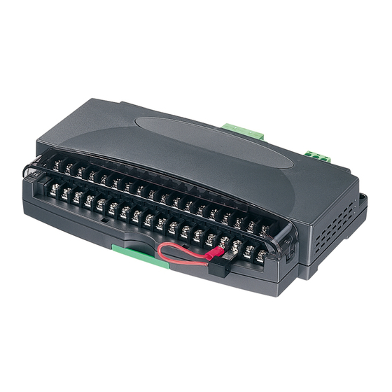
INSTRUCTION MANUAL
THERMOCOUPLE & DC INPUT MODULE
( 16 points; CC-Link Ver.1.10 / Ver.2.00 )
1. BEFORE USE .... .......................................................................................... 2
2. GENERAL DESCRIPTION ........................................................................... 3
3. POINTS OF CAUTION .................................................................................. 3
4. HARDWARE SPECIFICATIONS .................................................................. 4
5. COMPONENT IDENTIFICATIONS ............................................................... 5
6. INSTALLATION ............................................................................................ 5
7. TERMINAL CONNECTIONS ........................................................................ 6
7.1.
EXTERNAL DIMENSIONS ...........................................................................................................6
7.2. CONNECTION DIAGRAM ............................................................................................................7
8. INPUT RANGE SELECTING ........................................................................ 8
9. CONNECTING DATA LINK WIRES .............................................................. 9
9.1. TWISTED-PAIR CABLE ................................................................................................................9
9.2. POINTS OF CAUTION IN HANDLING WIRES .............................................................................9
9.3. WIRING DIAGRAM .......................................................................................................................9
10. SELECTING CC-LINK VERSION ................................................................. 9
11. DATA LIST ...................................................................................................10
11.1. REMOTE I/O ...............................................................................................................................10
11.2. ASSIGNING REMOTE REGISTERS ..........................................................................................10
11.3. A/D CONVERSION .....................................................................................................................10
12. PARAMETERS SETTING BY PLC PROGRAM ..........................................11
12.1. GENERAL DESCRIPTION ........................................................................................................ 11
13. TROUBLESHOOTING .................................................................................12
13.1. L ERR. INDICATOR BLINKING ...................................................................................................12
13.2. L ERR. INDICATOR ON ..............................................................................................................12
13.3. L RUN INDICATOR OFF .............................................................................................................12
13.4. UNABLE TO READ/WRITE DIGITAL VALUES? .........................................................................12
14. CHECKING ..................................................................................................13
15. ADJUSTMENT PROCEDURE .....................................................................13
16. MAINTENANCE...........................................................................................13
17. LIGHTNING SURGE PROTECTION ...........................................................13
Cont en t s
5-2-55, Minamitsumori, Nishinari-ku, Osaka 557-0063 JAPAN
Phone: +81(6)6659-8201 Fax: +81(6)6659-8510 E-mail: info@m-system.co.jp
R1C-GH
MODEL
EM-5956 Rev.11 P. 1 / 13
Advertisement
Table of Contents

Related Manuals for M-system R1C-GH


Summary of Contents for M-system R1C-GH
-
Page 1: Table Of Contents
13.3. L RUN INDICATOR OFF ......................12 13.4. UNABLE TO READ/WRITE DIGITAL VALUES? .................12 14. CHECKING ....................13 15. ADJUSTMENT PROCEDURE ..............13 16. MAINTENANCE...................13 17. LIGHTNING SURGE PROTECTION ............13 EM-5956 Rev.11 P. 1 / 13 5-2-55, Minamitsumori, Nishinari-ku, Osaka 557-0063 JAPAN Phone: +81(6)6659-8201 Fax: +81(6)6659-8510 E-mail: info@m-system.co.jp... -
Page 2: Before Use
R1C-GH 1. BEFORE USE ..Thank you for choosing M-System. Before use, please check contents of the package you received as out- lined below. If you have any problems or questions with the product, please contact M-System’s Sales Office or repre- sentatives. -
Page 3: General Description
R1C-GH 2. GENERAL DESCRIPTION The model R1C-GH, Thermocouple & DC Input Module, is used as remote device for CC-Link. Model number and suffix codes are designated as follows: R1C − GH2T −x MODEL I/O TYPE GH2 : Thermocouple or DC input, 16 points... -
Page 4: Hardware Specifications
Power input R1C-GH2T-M2 85 – 264V AC, 47 – 66 Hz R1C-GH2T-R 24V DC ±10% Power consumption R1C-GH2T-M2 Approx. 10VA R1C-GH2T-R Approx. 7W EM-5956 Rev.11 P. 4 / 13 5-2-55, Minamitsumori, Nishinari-ku, Osaka 557-0063 JAPAN Phone: +81(6)6659-8201 Fax: +81(6)6659-8510 E-mail: info@m-system.co.jp... -
Page 5: Component Identifications
Set the body so that its DIN rail adaptor is at the bottom. Pull down the DIN rail adaptor. Refer to “EXTERNAL DIMENSIONS.” DIN Rail Adaptor EM-5956 Rev.11 P. 5 / 13 5-2-55, Minamitsumori, Nishinari-ku, Osaka 557-0063 JAPAN Phone: +81(6)6659-8201 Fax: +81(6)6659-8510 E-mail: info@m-system.co.jp... -
Page 6: Terminal Connections
3 (.12) 163 (6.42) 40 (1.57) [6 (.24)] FOR WALL MOUNT. CJC SENSOR (model: CJM) 6.2 (.24) 36–M3 INPUT TERMINALS unit: mm (inch) EM-5956 Rev.11 P. 6 / 13 5-2-55, Minamitsumori, Nishinari-ku, Osaka 557-0063 JAPAN Phone: +81(6)6659-8201 Fax: +81(6)6659-8510 E-mail: info@m-system.co.jp... -
Page 7: Connection Diagram
Note 3: CC-Link version selector input is valid only at the moment of the power turned on. Firmware version 0B.00 or higher. Use the R1X Configurator Software (model: R1CON) or consult M-System to confirm the firmware version. Caution: FG1 terminal is NOT a protective conductor terminal. -
Page 8: Input Range Selecting
SW311 (ch 1 – ch 8) SW411 (ch 9 – ch 16) (*) Factory setting unless specific input types and ranges are specified when ordering EM-5956 Rev.11 P. 8 / 13 5-2-55, Minamitsumori, Nishinari-ku, Osaka 557-0063 JAPAN Phone: +81(6)6659-8201 Fax: +81(6)6659-8510 E-mail: info@m-system.co.jp... -
Page 9: Connecting Data Link Wires
10. SELECTING CC-LINK VERSION The R1C-GH is usable both for CC-Link Ver. 1.10 and Ver. 2.00. The contact status of the version selec- tor input at the moment of the power supplied determines the CC-Link version. Required node numbers depends upon the version No as shown below. -
Page 10: Data List
HOLD (no clearing output signal, keeping the value just before the abnormality). When the PLC recovers to normal operation and the R1C receives new data, the output restarts changing. EM-5956 Rev.11 P. 10 / 13 5-2-55, Minamitsumori, Nishinari-ku, Osaka 557-0063 JAPAN Phone: +81(6)6659-8201 Fax: +81(6)6659-8510 E-mail: info@m-system.co.jp... -
Page 11: Parameters Setting By Plc Program
H0002 H0010 Station information (set for the number of connected modules.) H0002 H0020 *1. 14xx where xx = R1C Station No. EM-5956 Rev.11 P. 11 / 13 5-2-55, Minamitsumori, Nishinari-ku, Osaka 557-0063 JAPAN Phone: +81(6)6659-8201 Fax: +81(6)6659-8510 E-mail: info@m-system.co.jp... -
Page 12: Troubleshooting
(e.g. Use a dry cell). Try to read out digital value. ties of noise interference via external wires. Check wiring and grounding. EM-5956 Rev.11 P. 12 / 13 5-2-55, Minamitsumori, Nishinari-ku, Osaka 557-0063 JAPAN Phone: +81(6)6659-8201 Fax: +81(6)6659-8510 E-mail: info@m-system.co.jp... -
Page 13: Checking
Warm up the module for at least 10 minutes. Apply 0%, 25%, 50%, 75% and 100% input signal. Check that the A/D conversion data for the respective input signal remains within accuracy described in the data sheet. When the A/D conversion data is out of tolerance, contact Factory or M-System’s local representa- tive.
Need help?
Do you have a question about the R1C-GH and is the answer not in the manual?
Questions and answers