Sign In
Upload
Manuals
Brands
National Instruments Manuals
Chassis
cDAQ-9179
National Instruments cDAQ-9179 Manuals
Manuals and User Guides for National Instruments cDAQ-9179. We have
2
National Instruments cDAQ-9179 manuals available for free PDF download: User Manual, Quick Start
National Instruments cDAQ-9179 User Manual (108 pages)
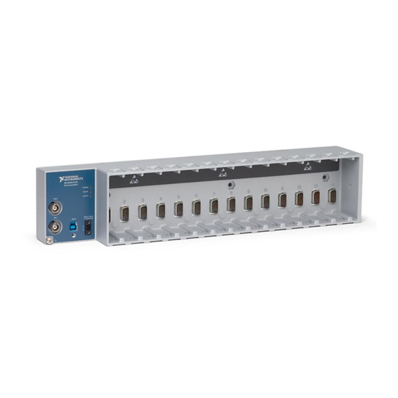
14-Slot USB 3.0 CompactDAQ Chassis
Brand:
National Instruments
| Category:
Chassis
| Size: 4.05 MB
Table of Contents
Table of Contents
6
Getting Started with the Cdaq Chassis
11
Safety Guidelines
11
Electromagnetic Compatibility Guidelines
12
Safety Guidelines for Hazardous Voltages
12
Hardware Symbol Definitions
13
Unpacking
13
Installing the Cdaq Chassis
14
Mounting the Cdaq Chassis
17
Installing the Desktop Mounting Kit
18
Using the Cdaq Chassis on a Desktop
18
Installing the Panel Mount Kit
20
Mounting the Cdaq Chassis on a Panel
20
Mounting the Cdaq Chassis on a DIN Rail
22
Panel Mounting Without a Panel Mount Kit
22
Mounting the Cdaq Chassis on a Rack
23
Cdaq Chassis Features
24
Chassis Grounding Screw
24
Leds
24
PFI 0 and PFI 1 BNC Connectors
24
Cables and Accessories
25
Power Connector
25
Removing C Series Modules from the Chassis
25
USB 3.0 Port and Cable Strain Relief
25
C Series Module
26
Using the Cdaq Chassis
26
Cdaq Module Interface
27
Parallel Versus Serial DIO Modules
27
Stc3S
27
Analog Input
29
Analog Input Timing Signals
29
Analog Input Triggering Signals
29
AI Convert Clock Signal Behavior for Analog Input Modules
30
AI Sample Clock Signal
30
AI Sample Clock Timebase Signal
30
Routing the Sample Clock to an Output Terminal
30
Scanned Modules
30
Sigma-Delta Modules
31
Simultaneous Sample-And-Hold Modules
31
AI Start Trigger Signal
32
Slow Sample Rate Modules
32
AI Reference Trigger Signal
33
Routing AI Start Trigger to an Output Terminal
33
Using a Digital Source
33
Using an Analog Source
33
AI Pause Trigger Signal
34
Routing the Reference Trigger Signal to an Output Terminal
34
Using a Digital Source
34
Using an Analog Source
34
Getting Started with AI Applications in Software
35
Using an Analog Source
35
Analog Output
36
Analog Output Data Generation Methods
36
Software-Timed Generations
36
Buffered Analog Output
37
Hardware-Timed Generations
37
Analog Output Timing Signals
38
Analog Output Triggering Signals
38
AO Sample Clock Signal
38
AO Sample Clock Timebase Signal
39
AO Start Trigger Signal
39
Routing AO Sample Clock to an Output Terminal
39
Routing AO Start Trigger Signal to an Output Terminal
39
Using a Digital Source
39
Using an Analog Source
39
AO Pause Trigger Signal
40
Using a Digital Source
40
Using an Analog Source
40
Getting Started with AO Applications in Software
41
Minimizing Glitches on the Output Signal
41
Digital Input/Output
42
Digital Input/Output and PFI
42
Serial DIO Versus Parallel DIO Modules
42
Digital Input
43
Digital Input Timing Signals
43
Digital Input Triggering Signals
43
Static DIO
43
Digital Input Filters
47
Change Detection Acquisition
48
Change Detection Event
48
Getting Started with DI Applications in Software
48
Routing Change Detection Event to an Output Terminal
48
Digital Output
49
Digital Output Data Generation Methods
49
Digital Output Timing Signals
51
Digital Output Triggering Signals
51
Digital Input/Output Configuration for ni 9401
54
Getting Started with DO Applications in Software
54
Pfi
54
PFI Filters
54
Counters
56
Counter Timing Engine
57
Counter Input Applications
58
Counting Edges
58
Single Point (On-Demand) Edge Counting
58
Buffered (Sample Clock) Edge Counting
59
Controlling the Direction of Counting
60
Pulse-Width Measurement
60
Implicit Buffered Pulse-Width Measurement
61
Single Pulse-Width Measurement
61
Pulse Measurement
62
Sample Clocked Buffered Pulse-Width Measurement
62
Implicit Buffered Pulse Measurement
63
Sample Clocked Buffered Pulse Measurement
63
Single Pulse Measurement
63
Semi-Period Measurement
64
Single Semi-Period Measurement
64
Implicit Buffered Semi-Period Measurement
65
Pulse Versus Semi-Period Measurements
65
Frequency Measurement
66
High Frequency with Two Counters
66
Low Frequency with One Counter
66
Large Range of Frequencies with Two Counters
67
Sample Clocked Buffered Frequency Measurement
69
Choosing a Method for Measuring Frequency
70
Which Method Is Best
71
Period Measurement
73
Measurements Using Quadrature Encoders
74
Position Measurement
74
Channel Z Behavior
75
Buffered (Sample Clock) Position Measurement
76
Measurements Using Two Pulse Encoders
76
Two-Signal Edge-Separation Measurement
77
Implicit Buffered Two-Signal Edge-Separation Measurement
78
Sample Clocked Buffered Two-Signal Separation Measurement
78
Single Two-Signal Edge-Separation Measurement
78
Counter Output Applications
79
Simple Pulse Generation
79
Single Pulse Generation
80
Single Pulse Generation with Start Trigger
80
Finite Pulse Train Generation
81
Pulse Train Generation
81
Retriggerable Pulse or Pulse Train Generation
81
Continuous Pulse Train Generation
82
Buffered Pulse Train Generation
83
Continuous Buffered Implicit Pulse Train Generation
84
Finite Buffered Sample Clocked Pulse Train Generation
84
Finite Implicit Buffered Pulse Train Generation
84
Continuous Buffered Sample Clocked Pulse Train Generation
85
Frequency Generation
86
Using the Frequency Generator
86
Frequency Division
87
Pulse Generation for ETS
87
Counter N Source Signal
88
Counter Timing Signals
88
Counter N Gate Signal
89
Routing a Signal to Counter N Gate
89
Routing a Signal to Counter N Source
89
Routing Counter N Source to an Output Terminal
89
Counter N A, Counter N B, and Counter N Z Signals
90
Counter N aux Signal
90
Routing a Signal to Counter N aux
90
Routing Counter N Gate to an Output Terminal
90
Routing Counter N Z Signal to an Output Terminal
90
Routing Signals to A, B, and Z Counter Inputs
90
Counter N HW Arm Signal
91
Counter N Sample Clock Signal
91
Counter N Up_Down Signal
91
Routing Signals to Counter N HW Arm Input
91
Counter N Internal Output and Counter N TC Signals
92
Frequency Output Signal
92
Routing Counter N Internal Output to an Output Terminal
92
Routing Counter N Sample Clock to an Output Terminal
92
Using an External Source
92
Using an Internal Source
92
Counter Triggering
93
Default Counter/Timer Routing
93
Routing Frequency Output to a Terminal
93
Cascading Counters
94
Other Counter Features
94
Prescaling
94
Synchronization Modes
94
80 Mhz Source Mode
95
External or Internal Source Less than 20 Mhz
95
80 Mhz Timebase
96
Clock Routing
96
Digital Routing
96
Digital Routing and Clock Generation
96
100 Khz Timebase
97
20 Mhz Timebase
97
Appendix A Where to Go from here
98
Advertisement
National Instruments cDAQ-9179 Quick Start (4 pages)
CompactDAQ 14-Slot USB 3.0 Chassis
Brand:
National Instruments
| Category:
Chassis
| Size: 3.31 MB
Advertisement
Related Products
National Instruments Eight-slot USB Chassis NI cDAQ-9172
National Instruments cDAQ-9174
National Instruments cDAQ-9178
National Instruments cDAQ-9171
National Instruments NI cDAQ-9181
National Instruments NI cDAQ-9188
National Instruments NI cDAQ-9191
National Instruments CompactDAQ cDAQ-9185
National Instruments CompactDAQ cDAQ-9189
National Instruments cDAQ-9188XT
National Instruments Categories
Control Unit
I/O Systems
Controller
Computer Hardware
Measuring Instruments
More National Instruments Manuals
Login
Sign In
OR
Sign in with Facebook
Sign in with Google
Upload manual
Upload from disk
Upload from URL