
Related Manuals for Lincoln SKF 85747


Summary of Contents for Lincoln SKF 85747
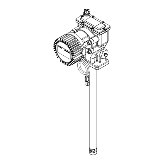
- Page 1 Installation instructions FlowMaster II rotary driven V electric pump, series “A” Models , U.S. gallons, , U.S. gallons, , lbs. Date of issue August Form number Version ...
- Page 2 Contents Declaration of Conformity* .. U.K. Declaration of Conformity* .. Safety .........
-
Page 3: Declaration Of Conformity
RoHS Directive //EU I, the undersigned of Lincoln Industrial Corporation, do hereby declare that the equipment specified above, in its intended use, conforms to the requirements of the above directives and harmonized standards at the time of placing the above product on the market. - Page 4 Common safety requirements I, the undersigned of Lincoln Industrial Corporation, hereby declare that the equipment specified above, in its intended use, conforms with all requirements of the U.K. legislation Supply of Machinery (Safety) Regulations No. by the time of placing it on the market.
-
Page 5: Explanation Of Signal Words For Safety
Safety Explanation of signal NOTE* Do not operate equipment without words for safety wearing personal protective gear. Read and carefully observe these installation Wear eye protection. Protective instructions before installing/operating/ equipment such as dust mask, non-skid troubleshooting the assembly. The assembly safety shoes, hard hat, or hearing NOTE must be installed, maintained and repaired... - Page 6 Description Damaged pumps Lincoln Industrial rotary V electric Do not use pump that appears to be pump uses V motor and single or two damaged, badly worn or operates stage planetary gear drive. Grease output is abnormally. Remove pump from service and proportional to pump revolutions per contact nearest service center for repairs.
- Page 7 Fig. Wiring diagram Item Description V Battery + Fuse Amp Red wire, motor positive Motor Black wire, motor negative Optional vent valve Battery - ) System control contacts, manual switch, or other form of system control. NOTE Connect red motor lead to positive side of circuit.
- Page 8 Fig. Pump dimensions 9.13 in (232 mm) 6.97 in 5.84 in (177 mm) (148 mm) 2.72 in (69 mm) / NPTF Ø 1.25 in (32 mm) Dimensions Model Dimension “A” Dimension “B” . in (349 mm) . in (576) ...
- Page 9 Install pump Install high pressure shut-off valve in Model material supply line (required). V .: gear ratio, stage Pump was tested in lightweight oil left in to Refer to Fig. and , page and to Back pressure Current protect pump from corrosion.
-
Page 10: Operation
Crankcase oil service interval Operation NOTE Do not change pump settings until after • Check oil level every hours of start up procedure. Motor used in operation, or monthly. V FlowMaster II pump is • Change oil every hours of operation equipped with built in speed control, or annually. - Page 11 Disassembly Fig. Remove gear box mounting screws (), washers () and gear box () ( Fig. ). † Loosen and remove screws () holding first Pump stage gear set (), spacer () and final 68 69 70 ...
- Page 12 Crank rod and eccentric Fig. Remove check rod from () lower bushing and plunger (). Remove pivot screws () from crank Remove ball () from lower bushing and rod () ( Fig. ). plunger (). † ...
- Page 13 Crank rod Fig. Loosen and remove flat head screws () from eccentric () ( Fig. ). † Remove counterbalance weights (). Remove outer () and inner (4) retaining ring from both sides of crank rod (). ...
- Page 14 Pump Assembly Fig. Install ball () into lower bushing and Crank rod and eccentric plunger () ( Fig. ). † assembly Insert check rod () into pump plunger (). Place crank rod () on in (63,5 mm) ...
- Page 15 Install wrist pin bushings () through crank Apply Loctite to threads of check seat Insert bronze bearing () into housing rod () and into wrist pin housing (). tube (). anchor () ( Fig. , page ). ...
- Page 16 Insert and thread screws () with Install shovel plug () into NOTE lock washers () into shaft cover () housing tube (). Refer to crankcase oil service interval, and pump housing (). Install spiral retaining ring (). page ...
- Page 17 Fig. IPB ...
- Page 18 Fig. IPB ...
- Page 19 Fig. IPB ...
- Page 20 Service parts list Item Description Part number Quantity Item Description Part number Quantity Flat head screw ( - x Woodruff key Counter weight Pump shaft Retaining ring ...
-
Page 21: Troubleshooting
Troubleshooting Condition Possible cause Corrective action Pump does not run. Pump is seized or damaged. Disassemble pump and repair any parts that are damaged or worn. Wired incorrectly. Connect red motor lead to positive battery terminal and black motor lead to negative terminal. - Page 22 This page left intentionally blank. ...
- Page 23 This page left intentionally blank. ...
-
Page 24: Warranty
| lincolnindustrial.com ® SKF, Lincoln and FlowMaster are registered trademarks of the SKF Group. ® Loctite is a registered trademark of Henkel Corp. © SKF Group The contents of this publication are the copyright of the publisher and may not be reproduced (even extracts) unless prior written permission is granted.
Need help?
Do you have a question about the SKF 85747 and is the answer not in the manual?
Questions and answers