Lincoln B Series Manual
Rf meter
Hide thumbs
Also See for B Series:
- Manual (58 pages) ,
- Service & operating manual (25 pages) ,
- Quick start manual (7 pages)
Table of Contents
Advertisement
Quick Links
GENERAL
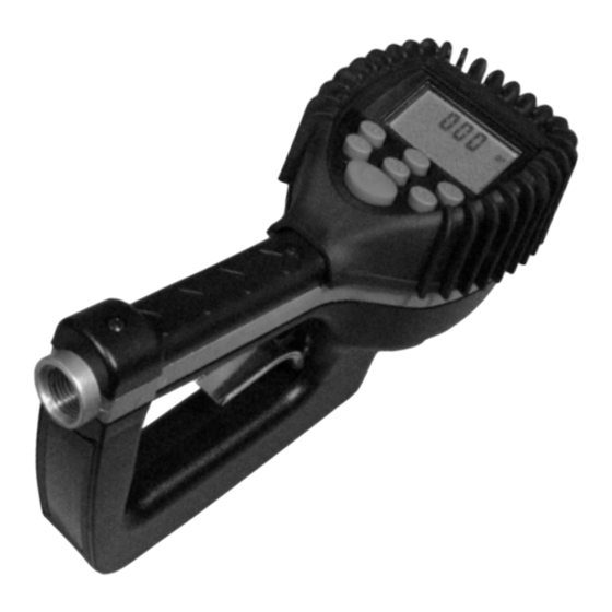
The RF meter is designed specifically to be used with the
LFC 2000 and LFC 2500 wireless Fluid Inventory Control and
Management Systems. The RF Meter will dispense bulk
fluids for servicing automobiles, trucks, buses, construction
equipment, and similar applications. The meter is lightweight,
rugged and has a comfortable grip. The meter is designed
specifically to dispense motor oils (S.A.E. 5-50), gear oils
(S.A.E. 80-240), automatic transmission fluid, and hydraulic
fluid.
A superior rugged, shock-resistant design for demanding
environments.
METER IS NOT FOR RESALE MEASUREMENT OF FLUID.
OPERATION
This unit can be programmed to dispense in quarts, liters,
pints, and gallons. A 5-digit liquid crystal display, accurate to
the second decimal point, shows the exact amount of fluid
dispensed.
The RF meter uses 4 replaceable AA batteries and is cali-
brated at the factory. The meter can also be recalibrated
easily in the field for a fluid of different viscosity.
LINCOLN'S FLUID INVENTORY CONTROL AND
MANAGEMENT SYSTEM OVERVIEW
Lincoln's Fluid Inventory Control and Management Systems
have been designed to offer greater control over the dispens-
ing of fluids with significant reductions in installation costs
and the associated hardware common to most hard-wired
systems today. Dispensing information and authority is
communicated from the keypad to the meter with actual
dispensing information being communicated back to the
keypad utilizing 902-928 Mhz frequency hopping spread
spectrum radio communications.
Tracking of all dispenses, by PIN number, Work Order
number, fluid type, Meter/Hose number allows the software to
compute the remaining fluid balances.
TYPICAL APPLICATIONS
•
Fleet Maintenance Shops
•
Industrial Assembly
•
Quick Lube Facilities
•
Dealerships
•
Construction and Mining Equipment
•
General Automotive Service Centers
•
Specialty Service and Repair Shops
IMPORTANT NOTE: The automatic nozzle requires 60 PSI to
open and function properly. A pump exceeding 60 PSI is
required for adequate flow and proper operation. A pump ratio
of at least 3:1 is recommended.
FEBRUARY 2006
(IOM-133-01 P/N 53400-133)
To order call 1-800-548-1191 or visit www.partdeal.com - info@partdeal.com
FCC ID: GIF-RF KEYPAD
FCC CERTIFIED, PART 15, SUBPART C
This device complies with Part 15 of the FCC Rules.
Operation is subject to the following two conditions: (1)
this device may not cause harmful interference, and (2)
this device must accept any interference received,
including interference that may cause undesired
operation.
FEATURES
•
Oval Gear Driven Meter
•
Durable, Rugged Design
•
Rubber Boot
•
Large, Easy-to-Read LCD Display
•
RF Communication Indicator
•
RF Controlled Meter
•
Totalization in Liters and Gallons
•
Delivery in Liters, quarts, Pints, Gallons
•
Automatic Non-Drip Nozzle with manual shut-off feature
•
Max. Totalizer Number: 99,999 Gallons or Liters
•
Max. Dispense Volume: 99,999 Units
•
Max. Preset Volume: 99.9 Units
•
Calibration Factor for Different Fluids
•
Changeable Units of Measure
•
Total and Resettable Total
•
Low Battery Indicator
•
Low Battery Safety Lock Out Feature
•
Uses Standard AA Batteries
•
In-Line Swivel
•
Automatic Shut-Off at Preset Amount
•
Emergency Electrical Shut-Off
•
Precision Control Valve Operation
Form 403595
RF Meter Manual
Model 915
Series "B"
RF METER
F60
Section -
Page -
5C
Advertisement
Table of Contents

Subscribe to Our Youtube Channel
Related Manuals for Lincoln B Series


Summary of Contents for Lincoln B Series
-
Page 1: Operation & Features Table Of Contents
LINCOLN’S FLUID INVENTORY CONTROL AND operation. MANAGEMENT SYSTEM OVERVIEW Lincoln’s Fluid Inventory Control and Management Systems FEATURES have been designed to offer greater control over the dispens- • Oval Gear Driven Meter ing of fluids with significant reductions in installation costs •... -
Page 2: Table Of Contents
___________________________________________________________________________________________________________________________________________________________________________________________ Table of Contents Operation & Features Table of Contents..........................1 Explosions and Fire Hazards..................2 Meter Hazards .......................3 FCC Compliance..........................3 METER OVERVIEW ........................4 Meter Buttons..........................4 LCD Display ............................5 METER INSTALLATION .........................5 Relieve System Pressure........................5 Grounding .......... -
Page 3: Meter Hazards
___________________________________________________________________________________________________________________________________________________________________________________________ FCC ID: GIF-RF KEYPAD FCC CERTIFIED, PART 15, SUB-PART C This device complies with Part 15 of the FCC Rules. Operation is subject to the following two conditions: (1) this device may not cause harmful interference, and (2) this device must accept any interference received, including interference that may cause undesired operation. -
Page 4: Meter Overview
___________________________________________________________________________________________________________________________________________________________________________________________ METER OVERVIEW The Electronic Preset Meter RF2 (EPM RF2) is equipped with RF (radio frequency) communications to communicate with a fluid management system keypad to get authorization and dispense information. This is referred to in the manual as the RF Mode. The meter can also be run as a standard EPM. -
Page 5: Lcd Display
___________________________________________________________________________________________________________________________________________________________________________________________ LCD Display 1. Displays re-settable total, accumulated total and Scale Factor 2. Displays Unit of Measure 3. Arrows flash when RF communication is in progress with the keypad 4. Preset Batch quantity 5. History Icon 6. AUTO is an indicator of being in EPM mode LCD Display 7. -
Page 6: Flushing Procedure
___________________________________________________________________________________________________________________________________________________________________________________________ Flushing Procedure If the system has multiple dispense NOTE: If this installation is new or if the fluid in the positions, begin at the position farthest from lines is contaminated, flush the system the pump and move towards the pump. before installing the meter(s). -
Page 7: Apply Nozzle To Meter
___________________________________________________________________________________________________________________________________________________________________________________________ Apply Nozzle to Meter 1. On the opposite end, apply sealant to the end of the ® nozzle. Recommended sealant is Loctite 243. 2. Thread the nozzle onto the meter. Screw it in tightly with an open ended, adjustable, wrench. 3. -
Page 8: History Icon
___________________________________________________________________________________________________________________________________________________________________________________________ 3. Pull the trigger to the full, up, position to begin the fluid flow. • The solenoid valve automatically locks the dispensing valve in the full open position. The trigger falls back to the closed position. • It is not necessary to continue to hold the trigger. •... -
Page 9: Error Codes
___________________________________________________________________________________________________________________________________________________________________________________________ Error Codes The meter has several Error Codes that may display. These provide indication, at the meter, that there is an error in communication between the meter and keypad. F01 The meter has received an invalid response from the keypad. •... -
Page 10: Meter Operation, Epm Mode
___________________________________________________________________________________________________________________________________________________________________________________________ METER OPERATION, EPM MODE The meter can be put in EPM Mode for start up purposes. Refer to the Supervisor’s Instruction Manual for key sequence. The AUTO icon displays, indicating the meter is in the EPM Mode. The solenoid valve unlocks and the meter can now be used as a Standard Preset Batch Meter. -
Page 11: Return To Rf Mode
___________________________________________________________________________________________________________________________________________________________________________________________ 2. Pull the trigger to begin the flow. • The meter solenoid valve automatically locks the dispensing valve in the full open position. The Batch trigger falls back to the closed position. Size The meter always locks in the maximum open position. •... -
Page 12: Operating Mode Functions
___________________________________________________________________________________________________________________________________________________________________________________________ OPERATING MODE FUNCTIONS These functions operate the same in RF Mode and EPM Mode. Re-settable/Accumulated Totals The meter has two flow totalizers. One is Re-settable Total the other is Accumulated Total. 1. To see the Accumulated Total and the Re-settable Total: •... -
Page 13: Service
___________________________________________________________________________________________________________________________________________________________________________________________ SERVICE Low Battery When the lithium batteries need changing a progression of warnings appears on the meter screen. First Warning: the Low Battery icon appears in the lower left corner of the display. That means the batteries are low and need to be changed when the icon appears. -
Page 14: Change Factory Settings
___________________________________________________________________________________________________________________________________________________________________________________________ CHANGE FACTORY SETTINGS Each meter is calibrated at the factory for use with motor oil (see Change Scale Factor, page 8). The Unit of Measure is also selected prior to shipment. Programming To change the factory settings: 1. Press the button to wake up the meter if Use a 5/32”... -
Page 15: Change Scale Factor
___________________________________________________________________________________________________________________________________________________________________________________________ Change Scale Factor Changing the Scale Factor changes the accuracy of the meter, potentially causing it to overfill or under fill. This has the potential to cause a mechanical breakdown. Scale Factor Digits 1. Press the button to advance through the Scale Factor digits. -
Page 16: Calculate Scale Factor
___________________________________________________________________________________________________________________________________________________________________________________________ CALCULATE SCALE FACTOR A Scale Factor is a number used to adjust meter accuracy. The Scale Factor is set at the factory using motor oil with a viscosity of 10W. The primary use for Scale Factor recalibration is to batch fluids with different viscosities. If the fluid has a lower viscosity, more fluid can slip past the meter gears without being detected. -
Page 17: Chart Of Scale Factors
__________________________ _____________________________________________________________________________________________________________________________________________________ ____________ Chart of approximate Scale Factors for fluids of different viscosities Scale Factor 1.08 1.07 1.06 1.05 1.04 1.03 1.02 1.01 1.00 0.99 0.98 1000 10000 Viscosity in Centistokes @ 65° Samples of Fluids, Viscosities and Scale Factors Fluid Viscosity Scale Factor 1.002... -
Page 18: Specifications
___________________________________________________________________________________________________________________________________________________________________________________________ SPECIFICATIONS English Metric Maximum Flow * 10 gpm 38 lpm Minimum Flow * 0.25 gpm 1 lpm Operating Pressure (Maximum) 1000 psi 67 bar Operating Pressure (Minimum) 5 psi .35 bar Operating Temperature (Maximum) 120° F 50° C Operating Temperature (Minimum) 20°... - Page 19 ___________________________________________________________________________________________________________________________________________________________________________________________ ITEM # PART DESCRIPTION PART NUMBER Battery Holder Assembly 274633 Bottom Case with 915 Radio 274608 ___________________________________________________________________________________________________________________ Form 403595 Page Number - 19 To order call 1-800-548-1191 or visit www.partdeal.com - info@partdeal.com...
- Page 20 ___________________________________________________________________________________________________________________________________________________________________________________________ ITEM # PART DESCRIPTION PART NUMBER Rubber Boot 274609 Display Assembly 274610 RF Register Assembly 274611 Not Shown Swivel, NPT 272397 ___________________________________________________________________________________________________________________ Form 403595 Page Number - 20 To order call 1-800-548-1191 or visit www.partdeal.com - info@partdeal.com...
- Page 21 ___________________________________________________________________________________________________________________________________________________________________________________________ ITEM # PART DESCRIPTION PART NUMBER Valve Assembly 282909 Gear Service Kit with O-Ring 272377 Trigger Assembly 273341 ___________________________________________________________________________________________________________________ Form 403595 Page Number - 21 To order call 1-800-548-1191 or visit www.partdeal.com - info@partdeal.com...
-
Page 22: Troubleshooting
___________________________________________________________________________________________________________________________________________________________________________________________ TROUBLESHOOTING Relieve the pressure prior to checking or repairing the meter. Make sure all valves, controls and pumps are operating correctly. Symptom Possible Cause Remedy Battery Icon is displayed Batteries are low Replace batteries Display Blank Meter asleep Push reset button Loose battery connection Remove battery pack and check battery connection / Push reset button... - Page 23 ___________________________________________________________________________________________________________________________________________________________________________________________ **Consists of Items 1, 2 and 3 ___________________________________________________________________________________________________________________ Form 403595 Page Number - 23 To order call 1-800-548-1191 or visit www.partdeal.com - info@partdeal.com...
- Page 24 In no event shall Lincoln be liable for incidental or consequential damages. Lincoln’s liability for any claim for loss or damages arising out of the sale, resale or use of any Lincoln equipment shall in no event exceed the purchase price. Some jurisdictions do not allow the exclusion or limitation of incidental or consequential damages, therefore the above limitation or exclusion may not apply to you.
Need help?
Do you have a question about the B Series and is the answer not in the manual?
Questions and answers