Table of Contents
Advertisement
Quick Links
Elm Trim Series
Elm Trim Series with TA-10 Flow Control Spindle & T-12A Cap Assembly
Installation & Operation Instructions
Model Numbers
TRIM ONLY
5500-TRM
Shower Valve Trim
5501-TRM
Shower Trim
5502-TRM
Tub/Shower Trim
5503-TRM
Hand Shower Trim
5505-TRM
Shower/Hand Shower Trim
5506-TRM
Tub/Shower/Hand Shower Trim
Compliance
•
ASME A112.18.1/CSA B125.1
Warranty
Limited Lifetime - to the original end purchaser in consumer/residential installations.
5 Years - for industrial/commercial installations.
Refer to www.symmons.com/warranty for complete warranty information.
Go to www.symmons.com/register to register your Symmons product.
Elm
®
TRIM, TA-10, T-12A
5500TRMTC
Shower Valve Trim
5501TRMTC
Shower Trim
5502TRMTC
Tub/Shower Trim
5503TRMTC
Hand Shower Trim
5505TRMTC
Shower/Hand Shower Trim
5506TRMTC
Tub/Shower/Hand Shower Trim
T-12A
TA-10
5400-TRM
5400TRMTC
5401TRMTC
5403-TRM
5403TRMTC
5405TRMTC
5401-TRM
5402-TRM
5402TRMTC
5405-TRM
5406-TRM
5406TRMTC
Advertisement
Table of Contents

Related Manuals for Symmons Elm 5500-TRM


Summary of Contents for Symmons Elm 5500-TRM
- Page 1 5405TRMTC 5406TRMTC Compliance • ASME A112.18.1/CSA B125.1 Warranty Limited Lifetime - to the original end purchaser in consumer/residential installations. 5 Years - for industrial/commercial installations. Refer to www.symmons.com/warranty for complete warranty information. Go to www.symmons.com/register to register your Symmons product.
- Page 2 1. Recommended Tools FIGURE 1 Adjustable Wrench Allen Wrench (3mm) Drill Phillips Screwdriver Safety Glasses Thread Seal Tape 2. Dimensions Measurements FIGURE 2 Ø 2-1/4", 57 mm 8", 203 mm 6", 152 mm 1/2" NPT thread must protrude 1/2" (13 mm) from finished wall Ref.
- Page 3 3. Parts Breakdown (Model Numbers Ending in TRMTC) Replacement Parts LIMIT STOP Item Description Part Number SCREW Cap Assy. T-12A Flow Control Spindle TA-10 IMPORTANT: Model numbers ending in TRMTC coordinate with Temptrol pressure balancing valves ordered with Test Cap. The Test Cap is used to allow pressurization of system.
- Page 4 7. Parts Breakdown Replacement Parts FIGURE 7 Item Description Part Number Showerhead 552SH Shower Arm 300S Flange 5505: Diverter Handle RTS-006 Set Screw 5506: RTS-039 Shower Handle RTS-006 Set Screw Dome Cover T-19 Dome Cover Diverter Escutcheon RTS-038 Screws Mounting Plate Dome Cover Shower Escutcheon RTS-005...
- Page 5 4) Install handle to shower valve. Secure with set screw (FIGURE 8.4). FIGURE 8.3 FIGURE 8.4 9. Installation - Diverter Valve Trim 1) Secure small mounting plate to Symmons diverter valve FIGURE 9.1 FIGURE 9.2 using mounting screws (FIGURE 9.1). 2) Secure small diverter escutcheon to mounting plate.
- Page 6 11. Installation - Slide Bar Assembly 1) Place mounting plate in position. Mark and drill 3/16" FIGURE 11.1 FIGURE 11.2 holes for tile anchors, 5/16" holes for drywall anchors. Install anchors (FIGURE 11.1). Note: For dry wall 1/2" thick or less, insert anchor tool into drywall anchor to secure behind wall prior to installing wall cradle.
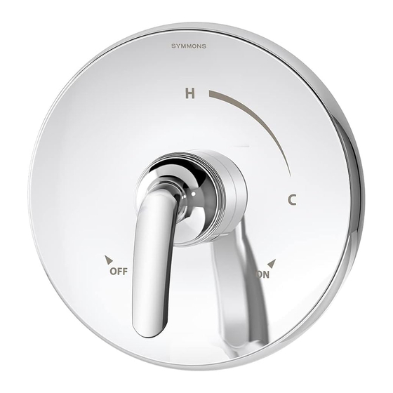
- Page 7 12. Operation (Temperature Control) 1) Turn shower handle counter-clockwise FIGURE 12.1 FIGURE 12.2 FIGURE 12.3 approximately 1/4 turn to put valve in cold position (FIGURE 12.1). 2) Turn shower handle counter- clockwise approximately 1/2 turn to put valve in warm position (FIGURE 12.2). 3) Turn shower handle counter- clockwise approximately 3/4 turn to put valve in hot position (FIGURE 12.3).
- Page 8 For more information, go to www.P65Warnings.ca.gov. ■ ■ ■ ■ Symmons Industries, Inc. 31 Brooks Drive Braintree, MA 02184 Phone: (800) 796-6667 Fax: (800) 961-9621 ■ ■ ■ ■ Copyright © 2019 Symmons Industries, Inc. symmons.com gethelp@symmons.com ZV-3282 REV A 062419...
Need help?
Do you have a question about the Elm 5500-TRM and is the answer not in the manual?
Questions and answers