
Related Manuals for Vortice VORT NRG HP


Summary of Contents for Vortice VORT NRG HP
- Page 1 Libretto Istruzioni Instruction booklet Livret d’instructions VORT NRG HP 5.471.084.809 15/01/2018...
-
Page 2: Table Of Contents
Introduction ....... . 86 La société Vortice ne pourra être tenue pour Sécurité... - Page 3 La Vortice Elettrosociali s.p.a. può essere contattata per fornire qualsiasi informazione riguardante l’utilizzo dei suoi prodotti. Vortice Elettrosociali s.p.a. attua una politica di miglioramento e sviluppo costante dei propri prodotti e si riserva il di- ritto di apportare modifiche alle specifiche, agli allestimenti e alle istruzioni riguardanti l’utilizzo e la manutenzione ogni momento e senza alcun preavviso.
-
Page 4: Introduzione
ITALIANO 1. INTRODUZIONE 1.1 Informazioni preliminari È proibita la riproduzione, la memorizzazione e la trasmissione, anche se parziale, di questa pubblicazione, in qual- siasi forma, senza l’autorizzazionepreventiva scritta da parte dell’Azienda. La macchina, a cui si riferiscono le presenti istruzioni, è stata progettata per gli utilizzi che saranno presentati nei pa- ragrafi appositi, compatibilmente con le sue caratteristiche prestazionali. - Page 5 ITALIANO 1.6 Rischi residui La macchina è stata progettata in modo da ridurre al minimo i rischi per la sicurezza delle persone che con essa andranno ad interagire. In sede di progetto non è stato tecnicamente possibile eliminare completamente le cause di rischio.
- Page 6 ITALIANO 1.7 Generalità sulla simbologia di sicurezza Simboli di sicurezza singoli in conformità alla norma ISO 3864-2: DIVIETO Un simbolo nero inserito in un cerchio rosso con diagonale rossa indica un’azione che non deve essere eseguita. AVVERTENZA Un simbolo grafico nero inserito in un triangolo giallo con bordi neri indica un pericolo.
- Page 7 ITALIANO 1.8 Simboli di sicurezza utilizzati PERICOLO GENERICO Osservare scrupolosamente tutte le indicazioni poste a fianco del pittogramma. La mancata osservanza delle indicazioni può gene- rare situazioni di rischio con possibili conseguenti danni alla sa- lute dell’operatore e dell’utilizzatore in genere. PERICOLO ELETTRICO Osservare scrupolosamente tutte le indicazioni poste a fianco del pittogramma.
- Page 8 ITALIANO 1.9 Limiti di utilizzo e usi non consentiti La macchina è stata progettata e costruita esclusivamente per gli usi descritti nel paragrafo “Limiti di utilizzo” del ma- nuale tecnico. Ogni altro impiego è vietato in quanto potrebbe generare rischi per la salute degli operatori e degli utiliz- zatori.
-
Page 9: Sicurezza
ITALIANO 2. SICUREZZA 2.1 Avvertimenti su sostanze tossiche potenzialmente pericolose 2.1.1 Identificazione del tipo di fluido impegnato: R410A • Difluorometano (HFC-32) 50% in peso CAS No.: 000075-10-5 • Pentafluoroetano (HFC-125) 50% in peso CAS No.: 000354-33-6 2.1.2 Identificazione del tipo di olio impiegato L ’... - Page 10 ITALIANO 2.3 Prevenire l’inalazione di elevate concentrazioni di vapore Le concentrazioni atmosferiche di refrigerante devono essere ridotte al minimo e mantenute quanto possibile al minimo livello, al di sotto del limite di esposizione professionale. I vapori sono più pesanti dell’aria, e concentrazioni pericolose possono formarsi vicino al suolo, dove la ventilazione generale è...
-
Page 11: Caratteristiche Tecniche
ITALIANO 2.6.2 Contatto con la pelle In caso di contatto con la pelle, lavare subito con acqua tiepida. Scongelare il tessuto epidermico con acqua. Rimuovere gli indumenti contaminati. Gli indumenti possono incollarsi alla pelle in caso di ustioni da gelo. Se vi è irritazione o pre- senza di vesciche, richiedere assistenza medica. - Page 12 ITALIANO 3.1.3 Compressori I compressori sono del tipo rotativo on/off, con resistenza del carter e relè termico di protezione annegato negli avvolgi- menti elettrici. I compressori sono installati sulla corrente d’aria in espulsione dal recuperatore verso l’esterno 3.1.4 Scambiatore sorgente Gli scambiatori sorgente sono realizzati in tubi di rame ed alette in alluminio.
- Page 13 Su richiesta è possibile installare una batteria di post riscaldamento esterna a canale ad acqua calda. 3.3.7 Configurazioni Le eventuali batterie di pre/post riscaldo etc vengono gestite come configurazioni come segue . VORT NRG HP xxx xx EHT = Con pre-heater elettrico per climi temperati integrato. EHR = Con pre-heater elettrico per climi rigidi integrato.
- Page 14 ITALIANO 3.4 Componenti dell’unità Configurazione macchina disponibile solo con ambiente a destra. Filtro aria esterna Scambiatore sorgente Ventilatore di mandata Quadro elettrico Serranda di bypass Pressostato filtri sporchi Servomotore serranda Display microprocessore/controllo di portata Recuperatore a controcorrente Sonda aria esterna Scambiatore utente US1 Sonda recupero Filtro di ripresa...
- Page 15 ITALIANO 3.5 Dati tecnici VORT NRG HP 1000 1500 2000 2500 3000 Portata aria nominale Prevalenza statica utile R410A R410A R410A R410A R410A R410A Refrigerante 3660 6420 9930 12590 16050 20160 Potenza totale recuperata riscaldamento °C 26,0 26,3 26,9 25,9...
- Page 16 ITALIANO Dati tecnici Le prestazioni sono riferite alle seguenti condizionii: (1) Riscaldamento: T emperatura aria esterna bulbo secco 7°C, umidità relativa 85%,aria ambiente 20/50°C (2) Riscaldamento: T emperatura aria esterna bulbo secco -5°C, umidità relativa 85%, aria ambiente 20/50°C (3) Raffreddamento: T emperatura aria esterna 35°C, umidità relativa 50%, aria ambiente 28/50°C (4) Livello di potenza sonora calcolato secondo ISO 9614 (versione LS) (5) Livello di pressione sonora misurato in campo libero, ad 1 metro dall’unità, fattore di direzionalità...
-
Page 17: Installazione
ITALIANO 3.6.4 Temperatura esterna Le unità sono progettate e costruite per operare in modalità inverno (modalità riscaldamento) tra -20°C e 20°C. In modalità raffreddamento le unità possono operare con una temperatura esterna tra i 20°C e i 43°C. In caso di operazioni al di fuori di questi valori siete pregati di contattare l’ A zienda. In caso di operazioni al di fuori di questi valori siete pregati di contattare l’Azienda. - Page 18 ITALIANO 4.3 Dispositivi di protezione individuali Gli operatori che effettuano l’installazione e la manutenzione della macchina devono indossare obbligatoriamente i dispositivi di protezione individuali previsti dalla legge elencati di seguito. Calzature di protezione Protezione degli occhi Guanti di protezione Protezione delle vie respiratorie Protezione dell’udito...
- Page 19 ITALIANO 4.4 Ricevimento ed ispezione All’atto dell’installazione o quando si debba intervenire sull’unità, è necessario attenersi scrupolosamente alle norme ri- portate su questo manuale, osservare le indicazioni a bordo unità e comunque applicare tutte le precauzioni del caso. La mancata osservanza delle norme riportate può causare situazioni pericolose. All’atto del ricevimento dell’unità, verifi- carne l’integrità: la macchina ha lasciato la fabbrica in perfetto stato;...
- Page 20 ITALIANO 4.8 Posizionamento e spazi tecnici minimi La macchina deve essere installata in modo dapermettere la mantenzione ordinaria e straordinaria. La garanzia non copre costi relativi a piattaforme o a mezzi di movimentazione neces- sari per eventuali interventi. Il sito di installazione deve essere scelto in accordo con le norme EN 378-1 e 378-3.
- Page 21 ITALIANO 4.9 Installazione plenum con attacchi circolari (PMBH) E’ possibile ordinare come accessorio il plenum con attacchi circolari : in lamiera zincata non isolata. E possibile ordi- nare 1 plenum per ogni bocca e quindi per un KIT completo è necessario acquistare nr 4 . plenum per il modello richiesto.
- Page 22 T utte le unità hanno dei ventilatori provvisti di presa di pressione che consentono di misurare l’effettiva portata d’aria ela- borata. T ramite un misuratore di pressione differenziale con la seguente tabella è possibile capire se la portata è quella corretta. VORT NRG HP 1000 1500...
- Page 23 Vista esterna Vista interna Il K factor per il corretto funzionamento viene già impostato di fabbrica. Nel caso di azzeramento di tale valore a titolo informativo si riporta la tabella dei K factor. VORT NRG HP 1000 1500 2000 2500...
- Page 24 ITALIANO Il cliente deve provvedere ad alimentare e proteggere singolarmente i singoli moduli secondo le potenze e le tensioni indicate: il contatto privo di tensione per il controllo della stessa è reso disponibile in morsettiera. Questo accessorio deve essere ordinato in fase d’ordine in quanto si rende alloggiare la sonda di aria esterna Cin nel modulo resistenza. Il cliente deve provvedere anche a cablare questa sonda all’interno del quadro elettrico secondo lo schema elettrico .
- Page 25 ITALIANO 1000 1500 2000 2500 3000 1040 Ø 1/2” 1/2” 3/4” 3/4” 3/4” 3/4” 1050 1200 V int. Peso 4.16 Estrazione filtri e recuperatore Per estrarre i componenti rimuovere i pannelli come illlustrato. 4.16.1 Versione A...
- Page 26 ITALIANO 4.16.2 Versione B 4.17 Scheda interfaccia seriale RS485 (INSE) Scheda seriale per interfacciamento al sistema di supervisione (disponibile solo sistema di supervisione MOD- BUSRS485) L ’ installazione della scheda permetterà all’unità di essere collegata e connessa ad un sistema con proto- collo MODBUS-RS485.
- Page 27 ITALIANO 4.18 Electrical connections: preliminary safety information The electrical cabinet is located inside the unit at the top of the technical compartment where the various components of the refrigerant circuit are also located. Remove the front panel of the unit to access the electrical cabinet. La connessione elettrica deve essere realizzata secondo lo schema elettrico allegato all’unità...
- Page 28 ITALIANO 4.19 Dati elettrici I dati elettrici riportati di seguito sono riferiti all’unità standard senza accessori. In tutti gli altri casi fare riferimento ai dati elet- trici riportati negli schemi elettrici allegati. La tensione di alimentazione non deve subire variazioni superiori a ±...
- Page 29 ITALIANO 4.21 Collegamenti elettrici Le numerazioni dei morsetti possono cambiare senza preavviso. Per i collegamenti è perciò necessario fare SEMPRE riferimeno allo schema elettrico fornito con l’unità. ALIMENTAZIONE UNITÀ Le unità sono alimentate con tensione 230/1/50; si raccomanda di interporre un seziona- tore generale sulla linea di alimentazione.
- Page 30 ITALIANO CONTATTO ESCLUSIONE COMPRESSORE (DCFL) Viene utilizzato per comandare l’accensione della resistenza di pre riscaldo eventualmente presente ( per il collegamento vedere schema elettrico) . SEGNALE 0-10V PER BATTERIA ACQUA CALDA (BPAC) Viene utilizzato per comandare l’apertura della vavola a 3 vie ( non fornita). (Per il collegamento vedere schema elettrico ) .
-
Page 31: Avviamento
ITALIANO 4.22 Schemi frigoriferi 4.22.1 Schema circuito frigorifero versione a 2 tubi YDSP2 YDSP1 Presa di carica Scambiatore sorgente Economizzatore Scambiatore sbrinamento recuperatore Valvola termostatica Capillare Filtro refrigerante Scambiatore utenze Spia del liquido Valvola unidirezionale Ricevitore di liquido Valvola inversione ciclo Compressore YDSP1 Valvola sbrinamento DSP YDSP2 Valvola sbrinamento DSP... - Page 32 ITALIANO 5.1.1 Prima della messa in funzione • Verificare che la macchina sia installata a regola d’arte e in conformità alle indicazioni di questo manuale. • Verificare l’allacciamento elettrico ed il corretto fissaggio di tutti i morsetti. • Verificare che la tensione sia quella riportata sulla targhetta dell’unità. •...
- Page 33 ITALIANO 5.2 Descrizione del controllore Tasto UP (navigazione a menù, scorrimento pa- Tasto modalità estate rametri, scorrimento valori parametri) Tasto DOWN (navigazione a menù, scorri- mento parametri, scorri- mento valori parametri.) Tasto modalità inverno Tasto SET (visualizzazione set-point, Tasto Menù accesso ai menù, conferma (accesso a navigazione valore del parametro du-...
- Page 34 ITALIANO 5.3 Pannello comandi remoto 5.3.1 Icone del display ICONA FUNZIONE Accese quando il display visualizza una temperatura Conteggio dell’intervallo tra sbrinamenti Presenza di allarme (lampeggiante). Accesa durante l’accesso al menù funzioni. Ventilatore Accesa se il relativo compressore è acceso: è lampeggiante se ul com- pressore è...
-
Page 35: Uso
ITALIANO 5.3.3 Installazione Il terminale remoto va montato a pannello, su foro 72x56 mm, e fissato con viti. Per ottenere una protezione frontale IP65 utilizzare la gomma di protezione frontale mod. RGW-V (opzionale). Per il fissaggio a muro e’ disponibile un adattatore per tastiere verticali V-KIT . Per i collegamenti elettrici al pannello comandi remoto riferirsi allo schema elettrico fornito con l’unità. - Page 36 ITALIANO Legenda: Accesa se l’uscita open collecto è attiva Funzione menù attiva. Icona ON (acceso): se le ventole sono accese. Resistenze integrative circuito utenza attive. Accesa se il relativo compressore è acceso; lampeggiante Accesa quando i ventilatori sono accesi. se il compressore è in temporizzazione di accensione Icona lampeggiante: T empo attesa inizio sbrinamento;...
- Page 37 ITALIANO 6.4 Come modificare i set point Quando si modificano o variano i parametri operativi della mac- china ssirucrarsi di non creare situazioni di conflitto con gli altri parametri impostati. La visualizzazione completa dei 2 set point (riscaldamento, raf- freddamento) è possibile SOLO quando l’unità è in modalità stand-by.
- Page 38 ITALIANO 6.5 Lista parametri Premendo il tasto l’utente ha la possibilità di visualizzare numerosi parametri. Scorrere la lista parametri usando i tasti , poi premere il tasto per visualizzare il parametro richiesto. In questo menù vi è solo la possibilità di visualizzare i parametri. Non è possibile modificare alcun valore. La lista parametri è: Display Lista...
-
Page 39: Manutenzione Unità
ITALIANO 7. MANUTENZIONE UNITÀ 7.1 Avvertenze generali La manutenzione permette di: • Mantenere efficiente la macchina. • Prevenire eventuali guasti. • Ridurre la velocità di deterioramento della macchina. Si consiglia di prevedere un libretto di macchina con lo scopo di tenere traccia degli interventi effettuati sull’unità... -
Page 40: Messa Fuori Servizio
ITALIANO 7.3.1 Ogni 6 mesi È buona norma eseguire controlli periodici per verificare il corretto funzionamento dell’unità. Controllare il corretto funzionamento degli organi di controllo e di sicurezza. • Controllare che i terminali elettrici sia all’interno del quadro elettrico che nelle morsettiere del compressore siano ben fissati. -
Page 41: Diagnosi E Risoluzione Problemi
ITALIANO • Evitare versamenti o perdite in ambiente. • Prima di scollegare la macchina recuperare se presenti: • Il gas refrigerante; • Le soluzioni incongelabili del circuito idraulico; • L ’ olio lubrificante dei compressori. In attesa della dismissione e dello smaltimento, la macchina può essere immagazzinata anche all’aperto, sempre che l’unità... - Page 42 ITALIANO Problema Sintomo Causa Rimedio T emperatura acqua utenza Attendere che la temperatura Allarme unloading compressore AEUn acqua utenza si abbassi. (solon unità con 2 compressori) troppo alta. Presenza di aria o sporcizia nell’im- Sfiatare lentamente l’impianto idrau- Allarme flussostato AHFL pianto idraulico acqua calda sanita- lico acquacalda sanitaria o control-...
-
Page 43: Schemi Dimensionali
ITALIANO Controllare il corretto funzio- Allarme termica ventilatore Corrente assorbita b1tF namento del ventilatore sor- sorgente. ad di fuori dei limiti operativi. gente e se necessario sostituirlo. Allarme termica Compres- Corrente assorbita Sostituire il compressore C1tr sore 1 ad di fuori dei limiti operativi. Allarme termica Compres- Corrente assorbita Sostituire il compressore... - Page 44 Vortice Elettrosociali s.p.a. can be contacted for any information regarding the use of its products. Vortice Elettrosociali s.p.a. implements a policy of continuous improvement and development of its products and reser- ves the right to make changes to the specifications, fittings and operating and maintenance instructions at any time and without notice.
-
Page 45: Introduction
ENGLISH 1. INTRODUCTION 1.1 Preliminary information Reproduction, recording, or transmission, even partial, of this publication in any form is prohibited without prior written authorisation from the Company. The machine to which these instructions apply has been designed for uses that will be presented in the corresponding paragraphs, in accordance with its performance characteristics. - Page 46 ENGLISH 1.6 Residual risks The machine has been designed to minimise risks to the safety of people with whom it will interact. It was not technically possible to completely eliminate the causes of risk in its design. Therefore, it is absolutely neces- sary to refer to the following requirements and symbols.
- Page 47 ENGLISH 1.7 General information on safety symbols Individual safety symbols in accordance with ISO 3864-2: PROHIBITED A black symbol inside a red circle with a red diagonal line indica- tes an action that should not be performed. WARNING A black graphic symbol inside a yellow triangle with black borders indicates a danger.
- Page 48 ENGLISH 1.8 Safety symbols used GENERIC HAZARD Carefully follow all instructions next to the pictogram. Failure to follow these instructions can generate risk situations with possible harm to the health of the operator and the user in general. ELECTRICAL HAZARD Carefully follow all instructions next to the pictogram.
- Page 49 ENGLISH 1.9 Limits of use and unauthorised uses This machine has been designed and built exclusively for the uses described in the "Limits of use" section of the te- chnical manual. Any other use is prohibited as it may create health risks to operators and users. The unit is however not suitable for operating in environments: •...
-
Page 50: Safety
ENGLISH 2. SAFETY 2.1 Warnings regarding potentially dangerous substances 2.1.1 Identification of the type of fluid used: R410A • Difluoromethane (HFC-32) 50% in weight CAS No.: 000075-10-5 • Pentafluoroethane (HFC-125) 50% in weight CAS No.: 000354-33-6 2.1.2 Identification of the type of oil used The lubricating oil used in the refrigerant circuit of the unit is of the polyester type. - Page 51 ENGLISH 2.3 Preventing the inhalation of high concentrations of vapour Atmospheric concentrations of refrigerant must be reduced to a minimum and kept as close as possible to minimum level, below the occupational exposure limit. Vapours are heavier than air and dangerous concentrations can form near the ground, where general ventilation is poor.
-
Page 52: Technical Characteristics
ENGLISH 2.6.2 Skin contact In case of skin contact, wash immediately with lukewarm water. Defrost epidermal tissue with water. Remove contamina- ted clothing. Garments may stick to the skin in case of frost burns. Seek medical attention if any irritation or blistering occurs. - Page 53 ENGLISH 3.1.3 Compressors The compressors are the on/off rotary type with crankcase heating and thermal protection relay embedded in electric windings. The compressors are installed on the expelled air stream from the heat recovery unit to the outside. Where present, crankcase heating is always powered when the unit is in stand-by mode. Compressor inspection can be performed through the side panel of the unit, which also allows maintenance even while the unit is in operation.
- Page 54 A hot water channel post-heating coil can be installed upon request. 3.3.7 Configurations Any pre / post heating batteries etc are managed as configurations as it follows. VORT NRG HP xxx xx EHT = With electric pre-heater for integrated temperate climates. EHR = With electric pre-heater for integrated rigid climates.
- Page 55 ENGLISH 3.4 Unit components Right-environment machine configuration available only. External air filter Source heat exchanger Supply fan Electrical cabinet Bypass damper Dirty filters pressure switch Damper servomotor Microprocessor/flow rate control display Counter cross heat recovery unit External air probe Normal duty exchanger US1 Recovery probe Recovery filter Delivery probe...
- Page 56 ENGLISH 3.5 Technical data 1000 1500 2000 2500 3000 VORT NRG HP 1000 1500 2000 2500 3000 Nominal flow rate Useful static prevalence R410A R410A R410A R410A R410A R410A Refrigerant 3660 6420 9930 12590 16050 20160 Total recovered heating power °C...
- Page 57 ENGLISH Performance is related to the following conditions: (1) Heating: Dry bulb dry air temperature 7°C, Relative humidity 85%,Ambient air 20/50°C (2) Heating: Dry bulb dry air temperature -5°C, Relative humidity 85%, Ambient air 20/50°C (3) Cooling: Outside air temperature 35°C, Relative humidity 50%, Ambient air 28/50°C (4) Sound power level computed according to ISO 9614 (LS version) (5) Sound pressure level measured in free field , 1 meter from the unit , diractionality factor Q=2 ISO9614 3.6 Limits of use...
-
Page 58: Installation
ENGLISH 3.6.4 Outside temperature Units have been designed and built to operate in winter mode (heating mode) between -20°C and 20°C. In cooling mode, the units can operate with an outside temperature between 20°C and 43°C. Please contact the Company in the event of operations outside these values. - Page 59 ENGLISH 4.3 Personal protective equipment Operators installing and maintaining the machine must wear the personal protective equipment required by law listed below. Protective footwear. Eye protection. Protective gloves. Respiratory protection. Hearing protection.
- Page 60 ENGLISH 4.4 Receipt and inspection When installing or when operating on the unit, strictly observe the rules contained in this manual, comply with the on-board instructions, and apply any precautions as appropriate. Failure to comply with these rules may result in hazardous situations.
- Page 61 ENGLISH 4.8 Positioning and minimum technical spaces The machine must be installed in such a way as to allow routine and special maintenance. The warranty does not cover costs related to platforms or han- dling systems required for any operations. The installation site must be chosen in accordance with EN 378- 1 and 378-3.
- Page 62 ENGLISH 4.9 Installation of the delivery and return plenum (PMBH) A delivery and return plenum in non-insulated galvanised sheet metal can be ordered as an accessory. 1 plenum can be ordered for each inlet and therefore it is necessary to purchase 4 plenums for a complete KIT for the requested model.
- Page 63 4.12 Calibrating the unit air flow rate All units have fans equipped with pressure plugs so that they can measure the actual flow of air. Use the differential pressure gauge with this table to understand if the flow rate is correct. VORT NRG HP 1000 1500...
- Page 64 ENGLISH External view Internal view The K factor for correct operation is pre-set in the factory. The K factor table is provided in the even that this value is reset. VORT NRG HP 1000 1500 2000 2500 3000 K factor 4.14 Pre-heating electric coil (BEBT)
- Page 65 ENGLISH The customer must ensure that individual modules are powered and protected individually according to the specified power and voltage: the voltage-free contact for its control is made available on the terminal board. This accessory has to be requested when placing the order as the outdoor air probe Cin is housed in the heating coil module. The customer must always wire this probe inside the electrical cabinet in accordance with the wiring diagram.
- Page 66 ENGLISH 1000 1500 2000 2500 3000 1040 Ø 1/2” 1/2” 3/4” 3/4” 3/4” 3/4” 1050 1200 V int. Weight 4.16 Filter and recovery unit removal Remove the panel as illustrated to remove components. 4.16.1 Version A...
- Page 67 ENGLISH 4.16.2 Version B 4.17 RS485 serial interface board (INSE) Serial board for supervision system interface (only available with MODBUS-RS485 supervision system). Board installa- tion will permit the unit to be connected to a MODBUS-RS485 protocol system. This system allows for remote monitoring of all unit operating parameters and to modify its values.
- Page 68 ENGLISH 4.18 Electrical connections: preliminary safety information The electrical cabinet is located inside the unit at the top of the technical compartment where the various components of the refrigerant circuit are also located. Remove the front panel of the unit to access the electrical cabinet. The electrical connection must be made according to the wiring diagram attached to the unit and in accordance with local and in- ternational regulations.
- Page 69 ENGLISH 4.19 Electrical data The following electrical data refers to the standard unit without accessories. In all other cases, refer to the electrical data in the attached wiring diagrams. The supply voltage must not be subject to variations greater than ±...
- Page 70 ENGLISH 4.21 Collegamenti elettrici Terminal numbering may change without notice. For connections it is therefore necessary to ALWAYS refer to the wiring diagram supplied with the unit. UNIT POWER SUPPLY The units are powered with voltage 230/1/50. It is advisable to interpose a main isolating switch on the power line.
- Page 71 ENGLISH COMPRESSOR EXCLUSION CONTACT (DCFL) Used to control any pre-heating electric coil start-up that may be present (see wiring diagram for connection). 0-10V SIGNAL FOR HOT WATER COIL (BPAC) Used to control opening of the 3-way valve (not supplied). (See wiring diagram for connection). Wiring diagram L1 N...
-
Page 72: Start Up
ENGLISH 4.22 Refrigerating diagrams 4.22.1 2-pipe version refrigerating circuit diagram YDSP2 YDSP1 Inlet valve Source heat exchanger Economiser Heat recovery unit defrosting heat exchanger Thermostatic valve Capillary Refrigerant filter Normal duty exchanger Liquid sight glass Unidirectional valve Liquid receiver Cycle reversing valve Compressor YDSP1 Defrosting valve DSP YDSP2 Defrosting valve DSP... - Page 73 ENGLISH 5.1.1 Prior to start-up • Make sure that the machine has been installed properly in accordance with the instructions in this manual. • Check the electrical connection and correct fastening of all terminals. • Check that the voltage is the same as that stated on the unit plate. •...
- Page 74 ENGLISH 5.2 Description of the controller UP key (menu navigation, parameter scrolling, Summer mode key parameter value scrolling, etc.) DOWN key (menu navigation, parame- ter scrolling, parameter value scrolling , etc.) Winter mode key SET key (set-point display, access to MENU key menus, parameter value (access to menu navigation)
- Page 75 ENGLISH 5.3 Remote control panel 5.3.1 Display icons ICONA FUNZIONE On when the display shows a temperature. Counting of the interval between defrosts. Alarm presence (flashing). On during access to functions menu. On if its compressor is on, flashing if the compressor is in ignition timing. On if auxiliary outputs are active.
-
Page 76: Use
ENGLISH 5.3.3 Installation The remote terminal should be panel mounted, on a 72x56 mm hole, and secured with screws. T o obtain an IP65 frontal protection, use the frontal protection rubber mod. RGW-V (optional). A vertical V-KIT keyboard adapter is available for wall mounting. For electrical connections to the remote control panel, refer to the wiring diagram supplied with the unit. - Page 77 ENGLISH Legend: On if the open collector output is active. Function menu active. Icon ON: if fans are on. Integrated normal duty circuit heating coil active. On if relative compressor is on, flashing if the compressor On when fans are on. is in ignition timing.
- Page 78 ENGLISH 6.4 How to modify set points When modifying or varying machine operating parameters, make sure not to create conflicting situations with the other set parame- ters. Full display of the 2 set points (heating, cooling) is possible ONLY when the unit is in stand-by mode. It is advisable to set the unit in stand-by mode when modifying set points.
- Page 79 ENGLISH 6.5 Parameters list Press the user button to view the numerous parameters. Scroll the parameters list using the keys, then press the key to view the desired parameter. It is only possible to view parameters in this menu. No values can be modified. The parameters list is: Display List Symbol...
-
Page 80: Unit Maintenance
ENGLISH 7. UNIT MAINTENANCE 7.1 General warnings Maintenance allows you to: • Keep the machine running efficiently. • Prevent any faults. • Reduce the speed of machine deterioration. It is advisable to provide a machine manual with the purpose of tracking the operations performed on the unit, facilitating any troubleshooting. -
Page 81: Decomissioning
ENGLISH 7.3.1 Every 6 months It is a good idea to perform periodic checks to make sure that the unit is working properly. Check the correct functioning of control and safety devices. • Make sure that the electrical terminals both inside the electrical cabinet and in the compressor terminal board are securely fastened. -
Page 82: Diagnosis And Troubleshooting
ENGLISH • Do not spill or leak into the environment. • Before disconnecting the machine, recover if present: • Refrigerant gas • Anti-freeze solutions in the hydraulic circuit • Lubricating oil in compressors While awaiting dismantling and disposal, the machine can also be stored outdoors if the unit's electrical and refrigerant circuits are intact and closed. - Page 83 ENGLISH Problema Sintomo Causa Rimedio Normal duty water tempera- Wait for the normal duty water Compressor unloading alarm (only AEUn temperature to lower. units with 2 compressors) ture too high. Slowly vent the DHW hydraulic sy- Presence of air or dirt in the normal AHFL DHW flow metre alarm stem or check and clean the water...
-
Page 84: Dimensional Diagrams
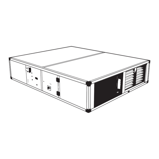
Absorbed current outside of Replace the compressor. C1tr Compressor 1 thermal alarm operating limits. Absorbed current outside of Replace the compressor. C2tr Compressor 2 thermal alarm operating limits. 10. DIMENSIONAL DIAGRAMS VORT NRG HP dimensional diagram... - Page 85 La Société Vortice S.p.A, qui peut être contactée pour fournir toute information concernant l'utilisation de ses produits. La Société Vortice S.p.A suit une politique de développement et d'amélioration constante de ses produits et se réserve le droit d'en modifier les spécifications, la préparation et toutes instructions relatives à...
-
Page 86: Introduction
FRANCAIS 1. INTRODUCTION 1.1 Informations Préliminaires Toute reproduction, stockage et transmission, même partielle de cette publication, sous quelque forme que ce soit est interdite, sans l'autorisation écrite préalable de la Société. L'appareil auquel se réfère ces instructions d’utilisation a été conçu pour les usages qui seront présentés dans les paragraphes appropriés, conformément à... - Page 87 FRANCAIS 1.6 Risques résiduels L'appareil a été conçu afin de réduire au minimum les risques, pour la sécurité des personnes qui vont interagir avec lui. En phase de projet, il n’était pas techniquement possible d’éliminer complètement les causes de risque. Il est donc absolument nécessaire de se référer aux impératifs et symboles reportés ci-dessous.
- Page 88 FRANCAIS 1.7 Généralités sur les symboles de sécurité Les symboles de sécurité conformément à la norme ISO 3864-2 : INTERDICTION Un symbole en noir inséré dans un cercle rouge avec une diago- nale rouge indique une action qui ne doit pas être effectuée. MISE EN GARDE Un symbole graphique noir inséré...
- Page 89 FRANCAIS 1.8 Symboles de sécurité utilisés DANGER GÉNÉRAL Observer scrupuleusement toutes les indications placées à côté du pictogramme. Le non respect des indications peut entraîner des situations dangereuses avec dommages possibles pour la santé de l’opérateur et de l’utilisateur en général. DANGER ÉLECTRIQUE Observer scrupuleusement toutes les indications placées à...
- Page 90 FRANCAIS 1.9 Limites d'utilisation et usages interdits L'appareil a été conçu et construit exclusivement pour les utilisations décrites dans la section « Limites d’utilisation » du manuel technique. T oute autre utilisation est interdite car elle pourrait générer des risques pour la santé des opérateurs et des utilisateurs. L'appareil n est pas apte à...
-
Page 91: Sécurité
FRANCAIS 2. SÉCURITÉ 2.1 Mise en garde au sujet des substances toxiques potentiellement dangereuses 2.1.1 Identification du type de fluide impliqué : R410A • Difluoromethane (HFC-32) 50% in weight CAS No.: 000075-10-5 • Pentafluoroethane (HFC-125) 50% in weight CAS No.: 000354-33-6 2.1.2 Identification du type d’huile utilisé... - Page 92 FRANCAIS 2.3 Éviter l’inhalation de fortes concentrations de vapeur Les concentrations atmosphériques de fluide réfrigérant doivent être-autant que possible- réduites et maintenues au niveau le plus bas, au-dessous de la limite d’exposition professionnelle. Les vapeurs sont plus lourdes que l’air et des concentrations dangereuses peuvent se former près du sol, où...
-
Page 93: Caractéristiques Techniques
FRANCAIS 2.6.2 Contact avec la peau En cas de contact avec la peau, la laver immédiatement avec de l’eau tiède. Décongeler le tissu épidermique avec de l’eau. Enlever les vêtements contaminés. Les vêtements peuvent coller à la peau en cas d'engelures. S’il y a irrita- tion ou présence de cloques, demander immédiatement une assistance médicale. - Page 94 FRANCAIS 3.1.3 Compresseurs Les compresseurs sont de type rotatif marche/arrêt, avec résistance du carter et relais thermique de protection intégré dans le bobinage électrique. Les compresseurs sont installés dans le flux d’air en expulsion depuis récupérateur vers l’extérieur. La résistance du carter, si présente, est toujours alimentée lorsque l’appareil est en veille. L ’inspection des compresseurs est possible grâce au panneau latéral de l’appareil qui permet la manutention même avec des appareils en fonctionnement.
- Page 95 3.3.7 Configurations T outes les batteries avant / après chauffage sont gérées comme des configurations comme suit. VORT NRG HP xxx xx EHT = Avec préchauffeur électrique pour les climats tempérés intégrés. EHR = Avec préchauffeur électrique pour les climats rigides intégrés.
- Page 96 FRANCAIS 3.4 Composants de l'appareil Right-environment machine configuration available only. Filtre à air extérieur Source heat exchanger Ventilateur d'émission Electrical cabinet Amortisseur by-pass Dirty filters pressure switch 4 Amortisseur servomoteur Microprocessor/flow rate control display Récupérateur à contre-courant Sonde récupération Échangeur utilisateur US1 Sonde d'alimentation Filtre de récupération Cin Sonde d'alimentation...
- Page 97 FRANCAIS 3.5 Spécifications techniques 1000 1500 2000 2500 3000 VORT NRG HP 1000 1500 2000 2500 3000 Débit d'air nominal Pression statique R410A R410A R410A R410A R410A R410A Fluide réfrigérant 3660 6420 9930 12590 16050 20160 Puissance totale récupérée réchauffement °C...
- Page 98 FRANCAIS La performance est liée aux conditions suivantes: (1) Chauffage: T empérature de l'air extérieur bulbe sec 7°C, Humidité relative 85% , Air environnement 20/50°C (2) Chauffage: T empérature de l'air extérieur bulbe sec -5°C, Humidité relative 85%, Air environnement 20/50°C (3) Refroidissement: T empérature de l'air extérieur 35°C, Humidité...
-
Page 99: Installation
FRANCAIS 3.6.4 Température extérieure Les appareils sont conçus et construits de manière à fonctionner en mode Hiver (mode Chauffage) entre -20 ° C et 20 ° C. En mode Refroidissement, l'appareil peut fonctionner avec une température externe de 20 ° C à 43 ° C. Dans le cas d'opérations en dehors de ces valeurs, contacter la Société. - Page 100 FRANCAIS 4.3 Dispositifs de protection individuels Les opérateurs qui effectuent l’installation et l’entretien de la ma- chine doivent obligatoirement porter les équipements de protec- tion individuelle requis par la Loi, comme énumérés ci-dessous. Chaussures de protection. Protection des yeux Gants de protection. Protection des voies respiratoires.
- Page 101 FRANCAIS 4.4 Réception et inspection Au moment de l’installation ou lorsque vous devez agir sur l'appareil, il est nécessaire de suivre scrupuleusement les instructions reportées dans ce manuel, suivre les instructions à bord de l’appareil et toujours prendre toutes les précautions nécessaires.
- Page 102 FRANCAIS 4.8 Positionnement et espaces techniques minimaux L'appareil doit être installé de façon à permettre son entretien or- dinaire et extraordinaire. La garantie ne couvre pas les coûts liés aux plateformes ou mo- yens de levage requis pour ces interventions. Le site de l’installation doit être choisi conformément à...
- Page 103 FRANCAIS 4.9 Installation plénum avec pivots circulaires (PMBH) Il est possible de commander comme accessoire le plénum avec pivots circulaires : en acier galvanisé non isolé. Il est possible de commander 1 plénum pour chaque ouverture. Un KIT complet nécessite l'achat de 4 plénums pour le modèle choisi.
- Page 104 T ous les appareils ont des ventilateurs avec test de pression qui permettent de mesurer le débit d’air réellement traité. Dans le tableau suivant, à l’aide d’un manomètre différentiel, il est possible de comprendre si le débit est le bon. VORT NRG HP 1000 1500...
- Page 105 FRANCAIS Vue Externe Vue Interne Le facteur K pour un fonctionnement correct est déjà réglé à l’usine Pour votre information, en de cas de remise à zéro ci-joint le tableau des facteurs K VORT NRG HP 1000 1500 2000 2500...
- Page 106 FRANCAIS Le client doit alimenter et protéger les différents modules séparément selon des forces et des tensions indiquées : contact libre de potentiel pour le contrôle de la même est mis à disposition dans le bornier. Cet accessoire doit être commandé...
- Page 107 FRANCAIS 1000 1500 2000 2500 3000 1040 Ø 1/2” 1/2” 3/4” 3/4” 3/4” 3/4” 1050 1200 V int. Poids 4.16 Extraction Filtres et récupérateur Pour extraire les composants ôter les panneaux comme illustré. 4.16.1 Version A...
- Page 108 FRANCAIS 4.16.2 Version B 4.17 Carte Interface série RS485 (INSE) Carte de série pour l'interface au système de supervision (disponible uniquement pour système de supervision MODBUS-RS485). L'installation de la carte permet à l'appareil d'être branché et connecté à un système avec protocole MODBUS-RS485.
- Page 109 FRANCAIS 4.18 Connexions électriques : Informations préliminaires de sécurité Le panneau électrique est situé à l'intérieur de l'appareil à la partie supérieure du compartiment technique où se trouve également les différents composants du circuit réfrigérant. Pour accéder au panneau électrique, retirer le panneau avant de l'appareil.
- Page 110 FRANCAIS 4.19 Données électriques Les données électriques ci-dessous se rapportent à l'appareil standard sans accessoires. Dans tous les autres cas, se référer aux données électriques indiquées dans les schémas de câblage ci-joints. La tension d'alimentation ne doit pas varier de plus de ± 10% de la valeur nominale et le déséquilibre entre les phases doit être in- férieur à...
- Page 111 FRANCAIS 4.21 Connexions électriques La numérotation des terminaux peut changer sans préavis. Pour les connexions, il est donc nécessaire de TOUJOURS faire réfé- rence au schéma du circuit fourni avec l'appareil. ALIMENTATION ÉLECTRIQUE DE L'APPAREIL Les appareils sont alimentés en tension 230/1/50 ; il est recommandé d'intercaler un in- terrupteur général sur la ligne d'alimentation.
- Page 112 FRANCAIS CONTACT EXCLUSION COMPRESSEUR (DCFL) Il est utilisé pour commander l'allumage de la résistance de préchauffage, éventuellement présente (pour le raccordement voir le schéma électrique). SIGNAL 0-10 V POUR BATTERIES EAU CHAUDE (CABG) Il est utilisé pour commander l'ouverture de la vanne trois voies (non fourni). (Pour le raccordement voir le schéma électrique).
-
Page 113: Démarrage
FRANCAIS 4.22 SCHÉMAS RÉFRIGÉRANTS 4.22.1 Schéma du circuit réfrigérant Version à 2 conduites YDSP2 YDSP1 Prise de charge Échangeur Source Sauvegarde Échangeur Dégivrage Récupérateur Vanne thermostatique Capillaire Filtre réfrigérant Échangeur Utilisateur Voyant du Liquide Vanne unidirectionnelle Récepteur du Liquide Vanne d'inversion de cycle Compresseur YDSP1 Vanne DSP Dégivrage DSP YDSP2 Vanne Dégivrage DSP... - Page 114 FRANCAIS 5.1.1. Avant la mise en marche • Vérifier que l'appareil est installé dans les règles de l'art et en conformité aux recommandations énoncées dans ce manuel. • Vérifier la connexion électrique et la fixation correcte de tous les terminaux. •...
- Page 115 FRANCAIS 5.2 Description du contrôleur Touche UP (navigation dans les menus, défilement des pa- Touche mode Été ramètres, défilement valeurs des paramètres..) Touche DOWN (navigation dans les menus, défilement des paramètres, défilement valeurs des paramètres..) Touche mode Hiver Touche SET (affichage des paramètres à...
- Page 116 FRANCAIS 5.3 Clavier de commande à distance 5.3.1 Icônes d'affichage ICONA FUNZIONE Allumées lorsque l'écran affiche une température. Décompte de l'intervalle entre les dégivrages. Présence de l'alarme (clignotant). Allumée lors de l'accès au Menu Fonctions. Ventilateur Allumée si le compresseur correspondant est allumé ; elle clignote si le compresseur est en phase de démarrage.
-
Page 117: Utilisation
FRANCAIS 5.3.3 Installation Le terminal du contrôle à distance peut être monté sur un panneau, sur trou de perforation 72 x 56 mm, et fixé par des vis. Pour obtenir un degré de protection frontale IP 65, utiliser le caoutchouc de protection frontale mod. RGW-V (en option). - Page 118 FRANCAIS Légende: Allumée si la sortie open collector est active Function menu active. Icône ON (allumé): si les ventilateurs sont allumés. Résistances supplémentaires circuit utilisateur actives. Allumée si le compresseur correspondant est allumé ; cli- Allumée lorsque les ventilateurs sont activés. gnotante si le compresseur est dans en phase d'allumage Icône clignotante : T emps d'attente début de dégivrage ;...
- Page 119 FRANCAIS 6.4 Comment modifier les paramètres Lorsqu'on modifie les paramètres opérationnels ou lorsqu' ils va- rient, s'assurer de ne pas créer des situations de conflit avec les autres paramètres insérés. La visualisation totale des 2 paramètres sélectionnés (chauffage, refroidissement) est possible uniquement lorsque l'appareil est en mode «...
- Page 120 FRANCAIS 6.5 Liste des paramètres En appuyant sur la touche l'utilisateur a la possibilité d'afficher différents paramètres. Faire défiler la liste des paramètres en utilisant les touches, puis appuyer sur la touche correspon- dantepour visualiser le paramètre souhaité. Dans ce menu, il est uniquement possible de visualiser les paramètres. Il n'est pas possible de modifier les valeurs. La liste des paramètres est : Display Liste...
-
Page 121: Entretien De L'appareil
FRANCAIS 7. ENTRETIEN DE L'APPAREIL 7.1 Mise en garde générale L'entretien permet de : • Maintenir l'efficacité de l'appareil. • Empêcher d'éventuelles pannes. • Réduire la vitesse de détérioration de l'appareil. Il est conseillé de prévoir un livret de suivi des interventions ef- fectuées sur l'appareil pour en garder la trace facilitant la recher- che d'éventuelles pannes. -
Page 122: Mise Hors Service
FRANCAIS 7.3.1 Tous les 6 mois Il est conseillé d'effectuer des vérifications périodiques pour contrôler le bon fonctionnement de l'appareil. Vérifier le bon fonctionnement des dispositifs de contrôle et de sécurité. • Contrôler que les terminaux électriques dans l'armoire électrique et sur le bornier du compresseur sont solidement fixés. -
Page 123: Diagnostic Et Résolution Des Problémes
FRANCAIS • Éviter tout déversement ou de fuite dans l'environnement. • Avant de déconnecter l'appareil, récupérer si elle est présente : • Le gaz réfrigérant ; • Les solutions antigel du circuit hydraulique ; • L'huile lubrifiante du compresseur. En prévision de la mise hors service et de l'élimination de l'appareil, celui-ci peut également être entreposé à l'extérieur, à... - Page 124 FRANCAIS Problème Symptôme Cause Remède Alarme déchargement du compres- T empérature de l'eau utilisateur Attendre jusqu'à ce que la tempéra- AEUn seur (uniquement pour les appareils trop élevée. ture de captage de l'eau diminue. avec 2 compresseurs) Présence d'air ou de saleté dans le Purger lentement le système hydrau- Alarme calculateur de débit AHFL...
-
Page 125: Les Schémas Dimensionnels
Alarme thermique du com- Remplacer le compresseur. C1tr dehors des limites d’exploitation. resseur 1 Consommation de courant en dehors Alarme thermique du com- Remplacer le compresseur. C2tr des limites d’exploitation. presseur 2 10. LES SCHÉMAS DIMENSIONNELS Dimensions schéma VORT NRG HP... - Page 126 TAGLIANDO INTERVENTO IN GARANZIA CERTIFICATE OF WORK PERFORMED UNDER GUARANTEE COUPON INTERVENTION SOUS GARANTIE DATA INTERVENTO TIMBRO CENTRO ASSISTENZA DATE OF WORK - DATE INTERVENTION STAMP OF TECHNICAL ASSISTANCE CENTRE - CACHET SERVICE APRES-VENTE TAGLIANDO INTERVENTO IN GARANZIA CERTIFICATE OF WORK PERFORMED UNDER GUARANTEE COUPON INTERVENTION SOUS GARANTIE DATA INTERVENTO TIMBRO CENTRO ASSISTENZA...
- Page 127 Company will consider written applications for transfer. Should Assistenza Tecnica autorizzati da VORTICE ELETTROSOCIALI SPA, any defect arise in any Vortice product and a claim under guarantee il cui indirizzo è disponibile sull’elenco telefonico alfabetico o become necessary, the appliance should be carefully packed and contattando il numero verde 800.555.777.
- Page 128 GARANZIA - GUARANTEE - GARANTIE Per poter usufruire della garanzia il cliente deve compilare e rispedire a VORTICE ELETTROSOCIALI SPA, entro 8 giorni dall’acquisto, la “Parte 2” del tagliando di garanzia, all’indirizzo e con le modalità in tale parte riportate.
Need help?
Do you have a question about the VORT NRG HP and is the answer not in the manual?
Questions and answers