
Subscribe to Our Youtube Channel
Related Manuals for Cameo OTOS SP6


Summary of Contents for Cameo OTOS SP6
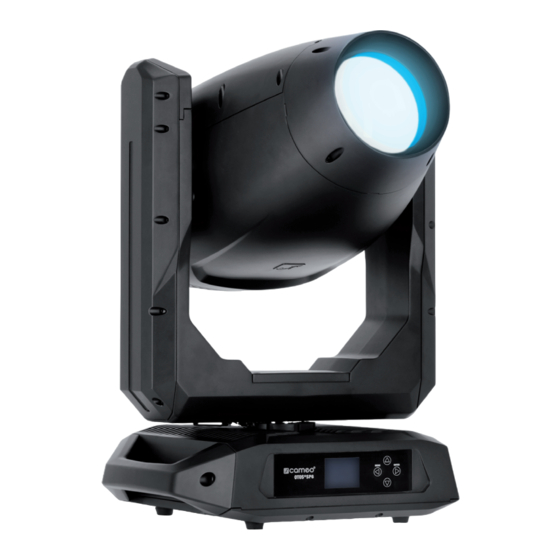
- Page 1 USER´S MANUAL BEDIENUNGSANLEITUNG MANUEL D`UTILISATION MANUAL DE USUARIO INSTRUKCJA OBSŁUGI MANUALE D‘ USO ANIMATION WHEEL OTOS SP6 OUTDOOR LED MOVING HEAD CLOTOSSP6...
-
Page 2: Table Of Contents
CONTENTS / INHALTSVERZEICHNIS / CONTENU / CONTENIDO / TREŚĆ / CONTENUTO ENGLISH INFORMATION ON THIS USER MANUAL INTENDED USE DEFINITIONS AND SYMBOL EXPLANATIONS SAFETY INSTRUCTIONS NOTES ON PORTABLE OUTDOOR DEVICES INCLUDED INTRODUCTION CONNECTIONS, OPERATING AND DISPLAY ELEMENTS OPERATION SETUP AND INSTALLATION CARE, MAINTENANCE AND REPAIR REPLACING GOBOS DIMENSIONS... - Page 3 MINDESTABSTAND ZUR BELEUCHTETEN FLÄCHE MINDESTABSTAND ZU NORMAL ENTFLAMMBAREN MATERIALIEN ENTSORGUNG HERSTELLERERKLÄRUNGEN FRANÇAIS INFORMATIONS SUR CE MANUEL D’UTILISATION UTILISATION PRÉVUE DÉFINITIONS ET EXPLICATION DES PICTOGRAMMES CONSIGNES DE SÉCURITÉ NOTES SUR LES APPAREILS PORTABLES POUR EXTÉRIEUR CONTENU DU CARTON INTRODUCTION BRANCHEMENTS, UTILISATION ET INDICATEURS FONCTIONNEMENT MONTAGE ET INSTALLATION ENTRETIEN, MAINTENANCE ET RÉPARATIONS...
- Page 4 CUIDADO, MANTENIMIENTO Y REPARACIÓN SUSTITUCIÓN DE GOBOS DIMENSIONES DATOS TÉCNICOS EXPLICACIÓN DE LA CLASE DE PROTECCIÓN IP DISTANCIA MÍNIMA A LA SUPERFICIE ILUMINADA DISTANCIA MÍNIMA A MATERIALES NORMALMENTE INFLAMABLES RECICLAJE DECLARACIONES DEL FABRICANTE POLSKI INFORMACJE NA TEMAT NINIEJSZEJ INSTRUKCJI OBSŁUGI ZAMIERZONE ZASTOSOWANIE DEFINICJE I OBJAŚNIENIA SYMBOLI INSTRUKCJE BEZPIECZEŃSTWA...
- Page 5 MATERIALE COMPRESO NELLA FORNITURA INTRODUZIONE CONNESSIONI, ELEMENTI DI COMANDO E DI VISUALIZZAZIONE FUNZIONAMENTO INSTALLAZIONE E CONFIGURAZIONE CURA, MANUTENZIONE E RIPARAZIONE SOSTITUZIONE DEI GOBOS DIMENSIONI DATI TECNICI SPIEGAZIONE DELLA CLASSE DI PROTEZIONE IP DISTANZA MINIMA DALLA SUPERFICIE ILLUMINATA DISTANZA MINIMA DAI MATERIALI NORMALMENTE INFIAMMABILI SMALTIMENTO DICHIARAZIONI DEL PRODUTTORE DMX CONTROL / DMX STEUERUNG / PILOTAGE DMX /...
-
Page 6: Information On This User Manual
This device has been developed and manufactured to the highest quality standards to ensure many years of problem-free operation. Please read this user manual carefully to be able to use your new Cameo product quickly and optimally. Further information about Cameo Light is availab- le on our website CAMEOLIGHT.COM. -
Page 7: Safety Instructions
This symbol indicates hazards caused by hot surfaces. This symbol indicates hazards caused by intense light sources. This symbol indicates a device in which there are no user-replaceable parts. This symbol indicates additional information on the operation of the product. SAFETY INSTRUCTIONS HAZARD: 1. - Page 8 5. Make sure that appropriate measures have been taken against overvoltage (e.g. lightning strike). 6. Observe the specified maximum output current on units with Power Out connec- tion. Ensure that the total current consumption of all connected devices does not exceed the specified value.
- Page 9 4. Use the original packaging or packaging provided by the manufacturer for transport. 5. Avoid shock or impact to the unit. 6. Observe the IP protection class as well as the ambient conditions such as tempera- ture and humidity according to the specification. 7.
-
Page 10: Notes On Portable Outdoor Devices
TRANSMISSION VIA W-DMX WARNING: In general, wireless DMX transmission must not be used for applications involving safety-related factors that might result in personal injury or property dama- ge in the event of a failure. This applies in particular to moving scene or traverse structures, DMX-controlled mo- tors/lifts or lifting devices for operating DMX-operated platform lifts, hydraulic systems or comparable moving components. -
Page 11: Included
2x Omega mounting brackets included. Operating voltage: 100–240 V AC. The spotlight features the RDM standard (Remote Device Management). This remote device management enables the status query and configuration of RDM end devices via an RDM-capable controller, such as the optionally available Cameo UNICON (item number CLIREMOTE). -
Page 12: Connections, Operating And Display Elements
Connection via supplied power cable (when not in use, always close with rubber sealing cap). POWER OUT IP65 power output socket with rubber sealing cap. Facilitates power supply to other CAMEO spotlights. Ensure that the total current consumption of all connected devices does not exceed the value specified on the device in amperes (A) (when not in use, always close with the rubber sealing cap). - Page 13 LC DISPLAY The illuminated display shows the currently activated mode (main display), the menu items in the main menu and sub-menus and the numerical value or status in certain menu items. If there is no control signal to the device, the characters in the centre of the display start flashing; the flashing stops as soon as a control signal is available (W-DMX, DMX and slave operation).
- Page 14 The battery-powered display can be activated, even if the device is not connected to the mains. To do this, press and hold MENU for about 10 seconds. You can now access device information to change and save system settings without mains connection. External control of the spotlight is not activated in this case.
-
Page 15: Operation
NOTES Once the fixture is correctly connected to the mains, the display will show "Software Update ...please wait", the software version, "Welcome to Cameo" and "...RESET" during the start-up procedure and motor reset. After this process, the spotlight is ready for operation and the previously activated operating mode is launched. The main display is activated automatically if no input is made within approximately 30 seconds. - Page 16 NOTE REGARDING THE MAIN DISPLAY IN OPERATING MODES WITH EXTERNAL CONTROL: As soon as the control signal is interrupted, the characters in the centre of the display begin to flash. The flashing stops when a control signal is present. Error message: If the warning symbol (triangle with exclamation mark) appears in the display, there is an error in one or more components of the unit.
- Page 17 Information on the submenu items in the DMX menu and the corresponding setting options can be found in the table below (select with and confirm with ENTER, change value or status with and confirm with ENTER). DMX Address 001 - 4xx Setting the DMX start address 33CH Basic...
- Page 18 Deactivate W-DMX reception Receive Activate W-DMX reception Unlink Disconnect W-DMX connections and put them in coupling standby Send to XLR Forwarding the control signal to XLR (DMX OUT) Signal Backup by XLR Control via XLR (DMX IN) with W-DMX signal interruption routing Receive only No connection between W-DMX signal and XLR connectors...
- Page 19 OPERATION VIA SACN Starting from the main display, press MENU to enter the main menu. Using and , select the Control menu and press ENTER. Now select the menu item sACN and confirm again. Information on the submenu items in the sACN menu and the corresponding setting options can be found in the table below (select with ...
- Page 20 Starting from the main display, press MENU to enter the main menu. Using and , select the Control menu, confirm, then select Stand Alone and confirm again. Now select Edit Scene, confirm, select the desired scene and confirm again. The scene is activated when confirmed and you can make the settings as desired (see table, select with ...
- Page 21 Ani. rot. 000 – 255 Animation Wheel Rotation Blade 1A 000 – 255 Blade 1A 0% <-> 100% Blade 1B 000 – 255 Blade 1B 0% <-> 100% Blade 2A 000 – 255 Blade 2A 0% <-> 100% Blade 2B 000 –...
- Page 22 Step 2 “ " User Scene 1 - User Scene 8 + Skip Step User scene selection + skip step Step 3 t-Step 0s - 20min Sets step time t-Fade 0s - 20min Sets fade time Step 4 " " Step 5 "...
- Page 23 Make the settings as desired (see table, select with and , confirm with ENTER, change value or status with and confirm with ENTER). Master/Alone Send to XLR Control signal is forwarded via DMX OUT Deactivate sending of the DMX control signal via W-DMX Master Activate DMX control signal forwarding via W-DMX Send to...
- Page 24 SYSTEM SETTINGS Starting from the main display, press MENU to enter the main menu. Select Settings using and and confirm with ENTER. Information on the submenu items in the Settings menu and the corresponding setting options can be found in the table below (select with and confirm with ENTER, change value or status with ...
- Page 25 Reverses pan direction Pan Reverse Does not reverse pan direction Reverses tilt direction Tilt Reverse Does not reverse tilt direction Automatic position correction is enabled Move- Position Feed- ment back Automatic position correction is disabled Blackout during head movement Move in Black No blackout during head movement Slowed pan and tilt movement Silent Movement...
- Page 26 Hold Last command is maintained if the control signal is interrupted In case of control signal interruption, the last activated stand- Last Stand Alone alone operation is started Fade to Black In case of control signal interruption, fade out to blackout takes Signal (10s) place for 10 seconds...
- Page 27 Run the selected engine. Motor stops when selecting Test Engine Test Tilt another motor and when leaving the menu level. … LED Calibration 0–255 Setting the maximum brightness across operating modes Cancel operation Reset Service Timer Reset now Reset service operation time Password For service purposes only SYSTEM INFORMATION...
- Page 28 Show DMX Displays the applied DMX values values Error Info Error display in case of malfunction DMX Table Display of DMX mode tables QUICKLIGHT Set up a scene quickly and easily using the basic Moving Head functions without an external controller.
-
Page 29: Setup And Installation
SETUP AND INSTALLATION Overhead mounting requires extensive experience, including the calculation of the load limit values of the installation material and regular safety inspection of all instal- lation materials and spotlights. If you do not have these qualifications, do not attempt to perform an installation yourself. -
Page 30: Replacing Gobos
ATTENTION: In order to maintain the IP65 tightness of the OTOS SP6 moving head, a new gasket must be inserted at the appropriate location after replacing a gobo. - Page 31 Disconnect the unit from the power supply at all poles (pull out the mains plug). Lock the headlamp head (pan and tilt lock). Loosen the hexagon socket screws of the unit head cover (see markings), remove the cover from the headlamp head, loosen the cover‘s safety rope and put it aside. Disconnect the two connectors for the voltage and signal supply of the gobo module.
- Page 32 Gobo wheel with the rotating gobos: Lift the gobo holder on the gear wheel slightly upwards and then pull it out of the gobo wheel. Gobo wheel with the fixed gobos: Turn the gobo wheel with the rotating gobos with the „Open“ opening over the desired gobo of the gobo wheel with the fixed gobos, press the gobo holder down slightly through the opening and then pull it out of the gobo wheel.
-
Page 33: Dimensions
Reattach the cover‘s safety rope to the appropriate place in the unit head and place the cover flat on the seal in the installation shaft surround. First tighten the middle and then the outer screws of the cover crosswise with gentle force. Then tighten the middle screws and then the outer screws crosswise to 6 (±... -
Page 34: Technical Data
TECHNICAL DATA Product number: CLOTOSSP6 Product type: LED moving light Type: IP65 Moving Head Number of lamps: Type of lamp: 600 W cool white LED Colour temperature (lamp): Fixed CCT LED @ 7000K Luminous flux: 18780 lm @ Zoom 205 Auto Fan / 4600 lm @ Fan Off Operation Colour rendering index (CRI): >70 LED PWM:... - Page 35 5-pin XLR IP65 IN/OUT; Ethernet IN/OUT; Lumen Radio Timo-Two Data connections: Control: DMX512; RDM enabled; Artnet; sACN; W-DMX (transceiver); CRMX ™ RDM functions: Cameo Standard RDM UID: 0x08A40500 (0000 -> FFFF) Operating controls: 4-button navigation (MENU/ENTER/UP/DOWN) Display elements: Illuminated LC display...
-
Page 36: Explanation Of Ip Protection Class
EXPLANATION OF IP PROTECTION CLASS 1. An IP rating only reflects protection from solid objects and water. It does not describe general weather resistance, such as protection from UV radiation and temperature, etc. 2. The first identification digit indicates protection from dust, solid objects and contact: IP2X Protected against solid foreign bodies ≥... -
Page 37: Disposal
DISPOSAL Packaging: 1. Packaging can be fed into the reusable material cycle using the usual disposal methods. 2. Please separate the packaging in accordance with the disposal laws and recycling regulations in your country. Device: 1. This appliance is subject to the European Directive on Waste Electrical and Electronic Equipment as amended. - Page 38 FCC STATEMENT This equipment has been tested and found to comply with the limits for a Class B digital device, pursuant to part 15 of the FCC Rules. These limits are designed to provide reasonable protection against harmful interference in a residential installation. This equipment generates, uses and can radiate radio frequency energy and, if not installed and used in accordance with the instructions, may cause harmful interference to radio communications.
-
Page 39: Deutsch
Dieses Gerät wurde unter hohen Qualitätsanforderungen entwickelt und gefertigt, um viele Jahre einen reibungslosen Betrieb zu gewährleisten. Bitte lesen Sie diese Bedienungsanleitung sorgfäl- tig, damit Sie Ihr neues Produkt von Cameo Light schnell und optimal einsetzen können. Weitere Informationen über Cameo Light erhalten Sie auf unserer Website CAMEOLIGHT.COM. -
Page 40: Sicherheitshinweise
Dieses Symbol kennzeichnet Gefahrenstellen oder gefährliche Situationen. Dieses Symbol kennzeichnet Gefahren durch heiße Oberflächen. Dieses Symbol kennzeichnet Gefahren durch intensive Lichtquellen. Dieses Symbol kennzeichnet ein Gerät, in dem sich keine vom Benutzer austauschba- ren Teile befinden. Dieses Symbol kennzeichnet ergänzende Informationen zur Bedienung des Produkts. SICHERHEITSHINWEISE GEFAHR: 1. - Page 41 2. Stellen Sie sicher, dass die Spannung und die Frequenz des Stromnetzes mit den auf dem Gerät angegebenen Werten übereinstimmen. Verfügt das Gerät über einen Spannungswahlschalter, schließen Sie das Gerät erst an, wenn dieser korrekt eingestellt ist. Nutzen sie nur geeignete Netzkabel. 3.
- Page 42 3. Die Gehäuseoberfläche des Geräts kann sich im regulären Betrieb stark erwärmen. Stellen Sie sicher, dass ein versehentliches Berühren des Gehäuses ausgeschlos- sen ist. Lassen Sie das Gerät vor dem Abbau, vor Wartungsarbeiten und vor dem Aufladen etc. immer ausreichend abkühlen. ACHTUNG: 1.
- Page 43 WARNUNG: Geräte mit kabelloser Signalübertragung sind nicht für den Betrieb in sensiblen Bereichen, in denen Funkbetrieb zu möglichen Wechselwirkungen führen kann, geeignet. Dazu zählen z.B.: • Krankenhäuser, Gesundheitszentren oder andere Einrichtungen des Gesundheitswe- sens, die Patientenbehandlungen mit Fachpersonal und -ausrüstung durchführen. •...
-
Page 44: Hinweise Für Ortsveränderliche Outdoor-Geräte
™ Omega-Montagebügel inklusive. Betriebsspannung 100 - 240 V AC. Der Scheinwerfer verfügt über den RDM-Standard (Remote Device Management). Diese Geräte- fernverwaltung ermöglicht die Statusabfrage und Konfiguration von RDM-Endgeräten über einen RDM-fähigen Controller, wie den optional erhältlichen Cameo UNICON (Artikelnummer CLIREMOTE). -
Page 45: Anschlüsse, Bedien- Und Anzeigeelemente
Anschluss mit Hilfe des mitgelieferten Netzkabels (bei Nichtgebrauch stets mit der Gummidicht- kappe verschließen). POWER OUT IP65 Netzausgangsbuchse mit Gummidichtkappe. Dient der Netzversorgung weiterer CAMEO Scheinwerfer. Achten Sie darauf, dass die gesamte Stromaufnahme aller angeschlossenen Geräte den auf dem Gerät in Ampere (A) angegebenen Wert nicht überschreitet (bei Nichtgebrauch stets mit der Gummidichtkappe verschließen). - Page 46 LC-DISPLAY Das beleuchtete Display zeigt die aktuell aktivierte Betriebsart an (Hauptanzeige), die Menüpunkte im Haupt- und den Untermenüs und den Zahlenwert bzw. Status in bestimmten Menüpunkten. Liegt kein Steuersignal am Gerät an, fangen die Zeichen in der Mitte des Displays an zu blinken, das Blinken stoppt, sobald ein Steuersignal anliegt (W-DMX, DMX- und Slave-Betrieb).
- Page 47 Das batteriegespeiste Display lässt sich aktivieren, selbst wenn das Gerät nicht am Stromnetz angeschlossen ist. Drücken und halten Sie hierfür MENU für die Dauer von circa 10 Sekunden. Sie können nun netzunabhängig Geräteinformationen auslesen und Systemeinstellungen ändern und abspeichern. Die externe Steuerung des Schein- werfers wird in diesem Fall nicht aktiviert.
-
Page 48: Bedienung
Sobald der Scheinwerfer korrekt am Stromnetz angeschlossen ist, wird während des Startvorgangs und des Motoren-Resets “Software Update ...please wait”, die Software-Version, “Welcome to Cameo” und “...RESET” im Display angezeigt. Nach diesem Vorgang ist der Scheinwerfer betriebsbereit und die Betriebsart, die zuvor aktiviert war, wird gestartet. - Page 49 HINWEIS ZUR HAUPTANZEIGE IN DEN BETRIEBSARTEN MIT EXTERNER STEUERUNG: Sobald das Steuer-Signal unterbrochen wird, beginnen die Zeichen in der Mitte des Displays zu blinken, liegt das Steuer-Signal wieder an, stoppt das Blinken. Fehlermeldung: Erscheint das Warnsymbol (Dreieck mit Ausrufezeichen) im Display, liegt bei einer oder mehreren Komponenten des Geräts ein Fehler vor.
- Page 50 Informationen zu den Untermenüpunkten im DMX-Menü und den entsprechenden Einstelloptionen finden Sie in untenstehender Tabelle (Auswahl mit und , bestätigen mit ENTER, Wert bzw. Status ändern mit und , bestätigen mit ENTER). DMX Address 001 - 4xx Einstellen der DMX-Startadresse 33CH Basic Mode 36CH Standard...
- Page 51 W-DMX DMX Address 001 - 4xx Einstellen der DMX-Startadresse 33CH Basic Mode 36CH Standard Auswählen des DMX-Modus 50CH Extended W-DMX Empfang deaktivieren Receive W-DMX Empfang aktivieren Unlink W-DMX Verbindungen trennen und in Koppelbereitschaft versetzen Send to XLR Weiterleiten des Steuersignals an XLR (DMX OUT) Signal Backup by XLR Ansteuerung per XLR (DMX IN) bei W-DMX Signalunterbrechung Routing...
- Page 52 Send to XLR Weiterleiten des Steuersignals an XLR Out Backup by XLR Ansteuerung per XLR bei ArtNet Signalunterbrechung Signal Routing Keine Verbindung zwischen Netzwerksignal und XLR-An- Receive only schlüssen BETRIEB VIA SACN Ausgehend von der Hauptanzeige gelangen Sie durch Drücken auf MENU in das Hauptmenü (Main Menu).
- Page 53 SZENE EDITIEREN (Edit Scene) Acht Szenen stehen zur Verfügung (Scene 1 – 8). Stellen Sie Pan, Tilt, Gobo, Pan / Tilt Makros usw. jeder Szene individuell direkt am Gerät mit Werten von 000 bis 255 ein. Ab Werk sind die Szenen vorprogrammiert.
- Page 54 Focus 000 - 255 0% <-> 100% Iris 000 - 255 0% <-> 100% Prism 000 - 255 Prism Prism rot. 000 - 255 Prism rotation Frost1 000 - 255 Frost 1 0% <-> 100% Frost2 000 - 255 Frost 2 0% <-> 100% Animation 000 - 255 Animation wheel Ani.
- Page 55 Daraufhin gelangen Sie in das Untermenü zum Einstellen der Untermenüpunkte (siehe Tabelle, Auswahl mit und , bestätigen mit ENTER, Wert bzw. Status ändern mit und , bestätigen mit ENTER). Die Einstellungen werden für jeden Loop separat vorgenommen und bleiben auch nach einem Neustart des Geräts erhalten.
- Page 56 MASTER / ALONE PLAY SCENE & PLAY LOOP Im Stand-Alone-Betrieb Play Scene und Play Loop kann das Steuersignal der Szenen und Loops via XLR (DMX OUT) und W-DMX an Slave-Einheiten ausgegeben werden (Control -> Stand Alone -> Master/Alone -> Master). Ist die Ausgabe des Steuersignals nicht gewünscht, kann die Ausga- be deaktiviert werden (Control ->...
- Page 57 Informationen zu den Untermenüpunkten im Slave-Menü und den entsprechenden Einstellop- tionen finden Sie in untenstehender Tabelle (Auswahl mit und , bestätigen mit ENTER, Wert bzw. Status ändern mit und , bestätigen mit ENTER). Slave XLR (permanent aktiv) W-DMX Modul aktivieren Wireless W-DMX Modul deaktivieren Unlink...
- Page 58 Die Lichtintensität lässt sich im unteren DMX-Wert- Logarithmic bereich grob und im oberen DMX-Wertbereich fein einstellen Curve Die Lichtintensität lässt sich im unteren und oberen S-Curve DMX-Wertbereich fein und im mittleren DMX-Wert- bereich grob einstellen Der Strahler reagiert abrupt auf Änderungen des Dimmer DMX-Werts Response...
- Page 59 Blackout bei Gobo- bzw. Farbraddrehung Move in Black Funktion deaktiviert Standardfunktion: Der xA-Kanal des Blades steuert Left & Right die linke Seite des Blades x und der xB-Kanal die Wheels rechte Seite. Framing Control Alternative Steuerung der Blendenschieber: Der xA- Position &...
- Page 60 Service Factory Zurücksetzen auf Werkseinstellung Zurücksetzen auf User A Werte (User Werte speichern: User A Settings -> Set Def. Values) Load Default Zurücksetzen auf User B Werte (User Werte speichern: User B Settings -> Set Def. Values) Zurücksetzen auf User C Werte (User Werte speichern: User C Settings ->...
- Page 61 xxx °C/°F Anzeige der Temperatur der entspre- Base xxx °C/°F chenden Komponente Temperature … °C Temperature Unit Einstellen der Temperatureinheit °F Fan Speed xxxx RPM Anzeige der Drehzahl des entsprechenden Lüfters Total xxxx h : xx m Gesamtbetriebszeit Operation xxxx h : xx m Nutzzeit Runtime xxxx h : xx m...
-
Page 62: Aufstellung Und Montage
AUFSTELLUNG UND MONTAGE GEFAHR: Überkopfmontage erfordert umfassende Erfahrung, einschließlich der Berechnung der Grenzwerte für die Arbeitslast, des verwendeten Installationsmate- rials und der regelmäßigen Sicherheitsüberprüfung aller Installationsmaterialien und Scheinwerfer. Wenn Sie diese Qualifikationen nicht haben, versuchen Sie nicht, eine Installation selbst durchzuführen, sondern nutzen Sie die Hilfe von professionellen Unternehmen. - Page 63 PFLEGE (vom Anwender durchführbar) WARNUNG! Vor jeglichen Pflegemaßnahmen müssen die Spannungsversorgung und sofern möglich sämtliche Geräteverbindungen getrennt werden. HINWEIS! Unsachgemäße Pflege kann zu Beeinträchtigung des Gerätes führen bis hin zur Zerstörung. 1. Gehäuseoberflächen müssen mit einem sauberen, feuchten Tuch gereinigt werden. Dabei ist darauf zu achten, dass keine Feuchtigkeit in das Gerät eindringen kann.
-
Page 64: Gobos Austauschen
Gobohalter eingesetzt werden, da sonst Hitz- eschäden an den Gobos und den Gobohaltern entstehen können! ACHTUNG: Um die Dichtheit des OTOS SP6 Moving Heads nach Schutzart IP65 zu erhalten, muss nach dem Austauschen eines Gobos an der entsprechenden Stelle eine neue Dichtung eingesetzt werden. - Page 65 Lösen Sie die beiden Stecker für die Spannungs- und Signalversorgung des Gobo-Moduls. Entfernen Sie nun die beiden Schrauben, die das Modul in der Führung halten und ziehen das Modul aus dem Scheinwerferkopf. Um die Gobos nicht zu verunreinigen, tragen Sie bitte fusselfreie Handschuhe. Legen Sie das Modul mit den Goborädern nach oben gerichtet auf eine saubere und ebene Unterlage.
- Page 66 Nun kann das Gobo aus der Halterung genommen und gegen ein anderes ausgetauscht werden. Setzen Sie danach die Gobohalterung wieder in das entsprechende Goborad und achten dabei darauf, dass die Gobohalterung korrekt in der Aussparung sitzt. Bei den rotierenden Gobos können Sie den korrekten Sitz durch Drehen des Goborads überprüfen, dabei muss das Gobo ohne zu haken rotieren.
-
Page 67: Abmessungen
ABMESSUNGEN (mm) 302,9 249,1... -
Page 68: Technische Daten
TECHNISCHE DATEN Artikelnummer: CLOTOSSP6 Produktart: LED Moving Light Typ: IP65 Moving Head Anzahl Leuchtmittel: Typ Leuchtmittel: 600 W kaltweiß LED Farbtemperatur (Leuchtmittel): Feste CCT LED @ 7000K Lichtstrom: 18780 lm @ Zoom 205 Auto Fan / 4600 lm @ Fan Off Operation Farbwiedergabe (CRI): >70 LED PWM:... - Page 69 5-Pol XLR IP65 IN/OUT; Ethernet IN/OUT; Lumen Radio Timo-Two FX Steuerung: DMX512; RDM enabled; Artnet; sACN; W-DMX (Transceiver); CRMX ™ RDM Funktionen: Cameo Standard RDM UID: 0x08A40500 (0000 -> FFFF) Bedienelemente: 4-Tasten Navigation (MENU / ENTER / UP / DOWN) Anzeigeelemente: Beleuchtetes LC-Display Akku für Bedienelemente und...
-
Page 70: Erläuterungen Zur Ip-Schutzart
ERLÄUTERUNGEN ZUR IP-SCHUTZART 1. Eine IP-Schutzart gibt ausschließlich den Schutz gegen feste Gegenstände, sowie Wasser wie- der. Sie beschreibt keine allgemeine Witterungsbeständigkeit, wie beispielsweise Schutz gegen UV-Strahlung und Temperatureinflüsse etc. 2. Die erste Kennziffer bezeichnet den Schutz gegen Staub, feste Gegenstände und Berührung: IP2X Geschützt gegen feste Fremdkörper mit Durchmesser ≥... -
Page 71: Entsorgung
ENTSORGUNG Verpackung: 1. Verpackungen können über die üblichen Entsorgungswege dem Wertstoffkreislauf zugeführt werden. 2. Bitte trennen Sie die Verpackung entsprechend der Entsorgungsgesetze und Wert- stoffverordnungen in Ihrem Land. Gerät: 1. Dieses Gerät unterliegt der europäischen Richtlinie für Elektro- und Elektronik-Alt- geräte in der jeweils geltenden aktuellen Fassung. -
Page 72: Français
Cet appareil a été conçu et produit suivant des exigences de qualité très strictes pour fonctionner pendant de nombreuses années. Veuillez lire attentivement ce manuel d’utilisation pour pouvoir utiliser rapidement et de manière optimale votre nouveau produit Cameo Light. Vous trouverez de plus amples informations sur Cameo Light sur notre site Web CAMEOLIGHT.COM INFORMATIONS SUR CE MANUEL D’UTILISATION... -
Page 73: Consignes De Sécurité
Ce pictogramme identifie les zones ou les situations dangereuses. Ce pictogramme indique les dangers causés par les surfaces portées à haute température. Ce symbole indique les dangers causés par des sources lumineuses intenses. Ce symbole indique qu'il n'y a pas de pièces remplaçables par l'utilisateur sur le site Ce pictogramme indique des informations supplémentaires concernant le fonctionne- ment du produit. - Page 74 2. Assurez-vous que la tension et la fréquence du réseau électrique correspondent aux valeurs indiquées sur l'appareil. Si l'appareil dispose d'un sélecteur de tension, ne connectez pas l'appareil avant de l'avoir réglé correctement. N'utilisez que des câbles secteur adaptés. 3. Pour déconnecter l'appareil du secteur sur tous les contacts, il ne suffit pas d'ap- puyer sur l'interrupteur marche/arrêt de l'appareil .
- Page 75 3. La surface du boîtier de l'appareil peut devenir très chaude lors d'un fonctionne- ment régulier. Veillez à ce qu'il ne soit pas possible de toucher accidentellement le boîtier. Laissez toujours la lampe refroidir suffisamment avant de la déposer, de l'entretenir, de la recharger, etc.
- Page 76 Rayonnement électromagnétique (par exemple, écrans vidéo LED, gradateurs) Toutes les valeurs de portée se réfèrent à une application en champ libre avec un contact visuel et sans interférence ! L'exploitation des systèmes émetteurs HF est soumise à des réglementations officielles. Celles-ci peuvent varier d'une région à l'autre et doivent être vérifiées par l'opérateur avant l'utilisation (par exemple, la fréquence radio et la puissance de transmission).
-
Page 77: Notes Sur Les Appareils Portables Pour Extérieur
Veuillez vérifier l'intégralité et l'intégrité de la livraison et informer votre partenaire de distribution immédiatement après l'achat si la livraison n'est pas complète ou si elle est endommagée. L'emballage comprend : X 1 x tête mobile OTOS SP6 X 1x cordon secteur X 2 x support oméga... -
Page 78: Branchements, Utilisation Et Indicateurs
Le projecteur est compatible avec le protocole RDM (Remote Device Management). Ce protocole de gestion à distance des appareils permet d'interroger leur état et de les configurer via un contrôleur compatible RDM, tel que le Cameo UNICON disponible en option (référence CLIREMOTE). BRANCHEMENTS, UTILISATION ET INDICATEURS POWER IN Embase secteur IP65 avec capuchon d’étanchéité... - Page 79 FUSIBLE Porte-fusible IP65 pour fusible 5 x 20 mm. REMARQUE IMPORTANTE : Remplacez le fusible uni- quement par un fusible de même type et de même valeur. Refermez soigneusement le porte-fu- sible de manière à ce que l’étanchéité IP65 soit toujours garantie. En cas de défaillance persis- tante des fusibles, veuillez prendre contact avec un centre de service autorisé.
- Page 80 ATTENTION : Pour garantir la protection IP65 contre les éclaboussures des con- necteurs DMX et réseau, les embases d'entrée et de sortie spéciales doivent être correctement scellées avec les connecteurs spéciaux IP65 ou par les capuchons d'étanchéité en caoutchouc. Lorsqu'elles sont correctement connectées ou scellées avec les capuchons d'étanchéité...
-
Page 81: Fonctionnement
REMARQUES : Une fois que le projecteur est correctement connecté au réseau, l'écran affiche "Software Update ...please wait", la version du logiciel, "Welcome to Cameo" et "... RESET" pendant la procédure de démarrage et de réinitialisation du moteur. Après cette opération, le projecteur est prêt à fonctionner et le mode de fonctionnement précédemment activé... - Page 82 Modes de fonctionnement autonomes Mode de fonctionnement esclave LED-Température LED-Température W-DMX Statut W-DMX Statut Mode Message Message d’erreur d’erreur Scène / Boucle / Sortie du signal REMARQUE CONCERNANT L'AFFICHAGE PRINCIPAL DANS LES MODES DE FONC- TIONNEMENT AVEC COMMANDE EXTERNE : Dès que le signal de commande est interrompu, les caractères au centre de l'écran commencent à...
- Page 83 STATUT W-DMX W-DMX W-DMX W-DMX W-DMX W-DMX W-DMX désactivé en tant que en tant que en tant que en tant que en tant récepteur récepteur récepteur récepteur qu'émetteur activé, activé, activé et activé et activé et non appairé appairé, appairé, appairé, Émetteur pas de...
- Page 84 Désactive l'envoi du signal de contrôle DMX via W-DMX Active la transmission du signal de contrôle DMX W-DMX Trans- via W-DMX mitter Appairage avec des appareils W-DMX prêts à être Force to pair appariés Unlink All Déconnecte toutes les connexions W-DMX FONCTIONNEMENT VIA W-DMX À...
- Page 85 UTILISATION VIA ART-NET À partir de l’écran principal, appuyez sur MENU pour accéder au menu principal. En utilisant et , sélectionnez le menu Control et appuyez sur ENTER. Sélectionnez ensuite l’élément de menu ArtNet et confirmez à nouveau. Vous trouverez dans le tableau ci-dessous des informations sur les sous-menus du menu ArtNet et les options de réglage correspondantes (sélectionnez avec ...
- Page 86 Vous trouverez dans le tableau ci-dessous des informations sur les sous-menus du menu sACN et les options de réglage correspondantes (sélectionnez avec et confirmez avec ENTER, modifiez la valeur ou l’état avec et confirmez avec ENTER). sACN DMX Address 001 - 4xx...
- Page 87 La scène est activée après confirmation et vous pouvez effectuer les réglages souhaités (voir tableau, sélectionner avec et confirmer avec ENTER, modifier la valeur ou l’état avec et confirmer avec ENTER). Edit Scene 000 – 255 0-100 Tilt 000 –...
- Page 88 Blade 1B 000 – 255 Blade 1B 0% <-> 100% Blade 2A 000 – 255 Blade 2A 0% <-> 100% Blade 2B 000 – 255 Blade 2B 0% <-> 100% Blade 3A 000 – 255 Blade 3A 0% <-> 100% Blade 3B 000 –...
- Page 89 Step 2 " " Sélection de scènes par l'utilisateur + User Scene 1 - User Scene 8 + Skip Step saut de pas Step 3 t-Step 0 s - 20 min Définit la durée du pas t-Fade 0 s - 20 min Règle la durée de fondu Pas 4 "...
- Page 90 Effectuez les réglages souhaités (voir tableau, sélectionnez avec et confirmez avec ENTER, modifiez la valeur ou l’état avec et confirmez avec ENTER). Master/Alone Le signal de commande est transmis via la sortie DMX Send to XLR Désactive l'envoi du signal de contrôle DMX via W-DMX Active la transmission du signal de contrôle DMX via Master...
- Page 91 Slave XLR (actif en permanence) Active le module W-DMX Désactive le module W-DMX Wireless Débranche toutes les connexions et met le projecteur en mode d'attente Unlink d'appairage PARAMÉTRES DU SYSTÉME (Settings) À partir de l’écran principal, appuyez sur MENU pour accéder au menu principal. Sélectionnez Settings à...
- Page 92 L’intensité lumineuse varie avec précision pour les Curve S-curve valeurs DMX basses et élevées, et plus grossière- ment pour les valeurs DMX intérmédiaires La luminosité varie brusquement aux changements de valeur DMX Response La luminosité émule celle d'une source halogène, Halogen Dimmer avec de légères variations de brillance...
- Page 93 La roue des couleurs revient directement au filtre de couleur Snap souhaité lorsque la valeur corre- Colour wheel Movement spondante est atteinte Rotation continue des roues Scroll chromatiques Blackout pendant la rotation des gobos ou de la roue chromatique Wheels Move in Black Fonction désactivée Fonction standard : Le canal xA de la lame contrôle...
- Page 94 Vous trouverez dans le tableau ci-dessous des informations sur les sous-menus du menu de ser- vice et les options correspondantes (sélectionnez avec et confirmez avec ENTER, modifiez la valeur ou l’état avec et confirmez avec ENTER). Service Factory Réinitialisation au réglage d'usine...
- Page 95 Vous trouverez dans le tableau ci-dessous des informations sur les sous-menus du menu System Info et les options correspondantes (sélectionnez avec et confirmez avec ENTER, modifiez la valeur ou l’état avec et confirmez avec ENTER) System Info DISP Vx.x.x Vx.x.x...
-
Page 96: Montage Et Installation
Si le mode Quicklight est activé, l’affichage ne passe pas automatiquement à l’affichage principal; lorsque vous quittez le menu Quicklight, le mode Quicklight est automatiquement désactivé. Les réglages du menu Quicklight sont conservés jusqu’au prochain redémarrage du projecteur ; il est donc possible d’accéder à... -
Page 97: Entretien, Maintenance Et Réparations
ENTRETIEN, MAINTENANCE ET RÉPARATIONS Afin de garantir le bon fonctionnement à long terme de l’appareil, celui-ci doit être régulièrement nettoyé et, si nécessaire, passer en maintenance . Le besoin de maintenance dépend de l’intensi- té de l’utilisation et de l’environnement dans lequel il est utilisé. Nous recommandons généralement une inspection visuelle avant chaque opération. -
Page 98: Remplacement Des Gobos
! ATTENTION: Afin de maintenir l'étanchéité IP65 de la tête mobile OTOS SP6, un nouveau joint doit être inséré à l'endroit approprié après le remplacement d'un gobo. - Page 99 Débranchez les connecteurs secteur et de signal du module de gobos. Retirez ensuite les deux vis qui maintiennent le module dans le guide et sortez le module de la tête du projecteur. Pour éviter de contaminer les gobos, veuillez porter des gants non pelucheux. Placez le module sur une surface propre et plane, les roues de gobos orientées vers le haut.
- Page 100 Replacez ensuite le support de gobo dans la roue de gobo, en veillant à ce que le support de gobo soit correctement placé dans le logement correspondant. Avec les gobos rotatifs, vous pouvez vérifier qu’ils sont correctement placés en tournant la roue de gobo ; le gobo doit tourner sans accrocher.
-
Page 101: Dimensions
DIMENSIONS (mm) 302,9 249,1... -
Page 102: Caracéristiques Techniques
CARACÉRISTIQUES TECHNIQUES Référence produit CLOTOSSP6 Type de produit : Tête mobile LED Type : Projecteur asservi IP65 Nombre de lampes : Type de lampe : 600 W LED blanc froid Température de couleur LED à TDC fixe @ 7000K (lampe) : 18780 lm @ Zoom 205, ventilateur automatique / 4600 lm Flux lumineux ventilateur désactivé... - Page 103 DMX512 ; RDM activé ; Artnet ; sACN ; W-DMX (émetteur-récep- ™ Contrôle : teur) ; CRMX Fonctions RDM Cameo Standard RDM UID : 0x08A40500 (0000 -> FFFF) Commandes de fonctionne- Navigation à 4 boutons (MENU/ENTER/UP/DOWN) ment : Éléments d’affichage : Écran LCD rétro-éclairé...
-
Page 104: Explication De La Classe De Protection Ip
Température ambiante de -20°C - 45°C fonctionnement : Diamètre de la lentille 130 mm Matériau du boîtier : Alliage de magnésium moulé sous pression Couleur du boîtier : Noir, finition peinture Époxy Refroidissement du boîtier : Ventilateur à température contrôlée 49,2 dB SPL si ventilateur en mode automatique ; 38,0 dB SPL Niveau sonore : @ ventilateur en mode silencieux ;... -
Page 105: Distance Minimale Par Rapport À La Surface Éclairée
4. En outre, certaines mesures spécifiques à l’appareil, telles que des couvercles et des capu- chons d’étanchéité, sont nécessaires pour atteindre la classe de protection spécifiée (par exemple, des capuchons de protection sur les connexions inutilisées). L'indice IP du produit figure dans les données techniques et est imprimé sur l'appareil. DISTANCE MINIMALE PAR RAPPORT À... -
Page 106: Déclarations Du Fabricant
DÉCLARATIONS DU FABRICANT GARANTIE DU FABRICANT ET LIMITATION DE RESPONSABILITÉ Adam Hall GmbH, Adam-Hall-Str. 1, D-61267 Neu Anspach / Courriel : Info@adamhall.com / +49 (0)6081 9419-0. Nos conditions de garantie et notre limitation de responsabilité actuelles peuvent être consultées en ligne à l’adresse suivante : https://cdn-shop.adamhall.com/media/pdf/Manufacturers-Declarations-CAMEO_DE_EN_ES_FR.pdf En cas de recours au service après-vente, veuillez contacter votre interlocuteur commercial. -
Page 107: Español
Este aparato ha sido desarrollado y fabricado siguiendo las normas de calidad más exigentes para garantizarle muchos años de funcionamiento sin problemas. Lea atentamente este manual de usuario para poder utilizar su nuevo producto Cameo de forma rápida y óptima. Encontrará más información sobre Cameo Light en nuestra página web CAMEOLIGHT.COM. -
Page 108: Instrucciones De Seguridad
Este símbolo identifica las zonas o situaciones peligrosas. Este símbolo indica peligro por superficie a alta temperatura. Este símbolo indica peligros causados por fuentes de luz intensas. Este símbolo indica que se trata de un aparato en el que no hay piezas sustituibles por el usuario. - Page 109 2. Asegúrese de que la tensión y la frecuencia de la red eléctrica coinciden con los valores indicados en el equipo. Si el equipo dispone de un selector de tensión, antes de enchufarlo a la red eléctrica, asegúrese de que el valor seleccionado es correcto.
- Page 110 ADVERTENCIA: 1. No instale ni opere el equipo cerca de radiadores, salidas de calefacción, estufas u otras fuentes de calor. Asegúrese siempre de que el equipo está instalado de forma que esté suficientemente refrigerado y no pueda sobrecalentarse. 2. No coloque fuentes de ignición, como velas encendidas, cerca del aparato. 3.
- Page 111 ADVERTENCIA: Los transmisores inalámbricos no deben utilizarse en zonas sensibles donde la radio puede provocar posibles interferencias. Entre las zonas sensibles están: • Hospitales, centros de salud u otros centros de atención sanitaria que prestan atención al paciente con personal y equipos especializados. •...
-
Page 112: Notas Sobre Los Dispositivos Portátiles De Exterior
El foco cuenta con el estándar RDM (gestión remota de dispositivos). Esta gestión remota de dis- positivos permite la consulta del estado y la configuración de los dispositivos finales RDM a través de un controlador compatible con RDM, como el Cameo UNICON disponible opcionalmente (número de artículo CLIREMOTE). -
Page 113: Conexiones, Mandos E Indicadores
Toma de salida de corriente IP65 con tapa de estanqueidad de goma. Facilita la alimentación de otros focos CAMEO. Asegúrese de que el consumo total de corriente de todos los aparatos conect- ados no supere el valor especificado en el aparato en amperios (A) (cuando no lo utilice, ciérrelo siempre con la tapa de cierre de goma). - Page 114 PANTALLA LC La pantalla iluminada muestra el modo activado en ese momento (pantalla principal), los ele- mentos del menú principal y de los submenús y el valor numérico o el estado en determinados elementos del menú. Si no hay ninguna señal de control en el aparato, los caracteres del centro de la pantalla empiezan a parpadear;...
- Page 115 La pantalla a pilas puede activarse aunque el aparato no esté conectado a la red eléctrica. Para ello, mantenga pulsado MENÚ durante unos 10 segundos. Ahora puede acceder a la información del aparato para cambiar y guardar los ajustes del sistema sin conexión a la red eléctrica.
-
Page 116: Funcionamiento
"Actualización de software ...por favor espere", la versión del software, "Bienvenido a Cameo" y "...RESET" durante el procedimiento de puesta en marcha y reinicio del motor. Tras este proceso, el foco está listo para funcionar y se pone en marcha el modo de funcionamiento previamente activado. - Page 117 NOTA RELATIVA A LA PANTALLA PRINCIPAL EN LOS MODOS DE FUNCIONAMIENTO CON CONTROL EXTERNO: En cuanto se interrumpe la señal de control, los caracteres del centro de la pantalla empiezan a parpadear. El parpadeo se detiene cuando hay una señal de control. Mensaje de error: Si aparece el símbolo de advertencia (triángulo con signo de exclamación) en la pantalla, significa que hay un error en uno o más componentes de la unidad.
- Page 118 FUNCIONAMIENTO MEDIANTE CABLE DMX Desde la pantalla principal, pulse MENU para entrar en el menú principal. Con y seleccione el menú Control y pulse ENTER. Seleccione ahora la opción de menú DMX y confirme de nuevo. En la siguiente tabla encontrará información sobre los elementos del submenú del menú DMX y las opciones de ajuste correspondientes (seleccione con ...
- Page 119 W-DMX DMX Address 001-4xx Ajustar la dirección de inicio DMX 33CH Basic Mode 36CH Standard Seleccionar el modo DMX 50CH Extended Desactivar la recepción W-DMX Activar la recepción W-DMX Receive Desconecte las conexiones W-DMX y póngalas en espera de Unlink acoplamiento Send to XLR Enviar la señal de control por el conector XLR (DMX OUT)
- Page 120 Activar (On) o desactivar (Off) el reenvío de la señal DMX a través de W-DMX. W-Transmitter Force to pair Establezca una conexión con otras unidades W-DMX (Forzar para emparejar) o desconéctelas (Desenlazar todas). Unlink All Send to XLR Reenvío de la señal de control a la salida XLR Signal Routing Backup by XLR Control mediante XLR con interrupción de señal ArtNet Receive only...
- Page 121 EDITAR ESCENA (Edit Scene) Hay ocho escenas disponibles (Scene 1-8). Ajuste el giro, la inclinación, el gobo, las macros de giro/inclinación, etc. de cada escena de forma individual directamente en la unidad con valores de 000 a 255. Las escenas están preprogramadas de fábrica. Desde la pantalla principal, pulse MENU para entrar en el menú...
- Page 122 Iris 000 - 255 0-100 Prism 000 - 255 Prisma Prism red. 000 - 255 (Rotación del prisma) Frost1 000 - 255 Escarcha 1 0% <-> 100% Frost2 000 - 255 Escarcha 2 0% <-> 100% Animation 000 - 255 Rueda de animación Ani.
- Page 123 De este modo accederá al submenú para ajustar los elementos del submenú (consulte la tabla, seleccione con y , confirme con ENTER, cambie el valor o el estado con y confirme con ENTER). Los ajustes de cada bucle se realizan de forma independiente y se conservan incluso después de reiniciar el equipo.
- Page 124 MASTER / SOLO REPRODUCIR ESCENA & REPRODUCIR BUCLE En el modo autónomo Play Scene y Play Loop, la señal de control de las escenas y los bucles puede emitirse a las unidades esclavas a través de XLR (DMX OUT) y W-DMX (Control -> Stand Alone ->...
- Page 125 En la siguiente tabla encontrará información sobre las opciones del submenú del menú esclavo y las opciones de ajuste correspondientes (seleccione y , confirme con ENTER, cambie el valor o el estado y , confirme con ENTER). Slave XLR (siempre activo) Activar el módulo W-DMX Desactivar el módulo W-DMX...
- Page 126 La intensidad de la luz puede ajustarse de forma Logarithmic más amplia en los valores DMX más bajos y con precisión en los valores DMX más altos Curve Ajustar la intensidad luminosa con precisión en los S-Curve valores DMX altos y bajos, y de forma más amplia en los valores DMX intermedios La luz responde bruscamente a los cambios en el Dimmer...
- Page 127 Rotación en el sentido de las Clockwise Position agujas del reloj Shortest Way Camino más corto La rueda de colores cambia Colour wheel directamente al filtro de color de- Snap seado cuando se alcanza el valor Movement correspondiente Giro continuo de las ruedas de Scroll colores Wheels...
- Page 128 En la siguiente tabla encontrará información sobre las opciones del submenú del menú de servi- cio y las opciones correspondientes (seleccione con y , confirme con ENTER, cambie el valor o el estado con y confirme con ENTER). Service Factory Restablecer ajustes de fábrica...
- Page 129 En la siguiente tabla encontrará información sobre los elementos del submenú del menú de información del sistema y las opciones correspondientes (seleccione con y , confirme con ENTER, cambie el valor o el estado con y confirme con ENTER) System Infomation DISP Vx.x.x...
-
Page 130: Configuración E Instalación
Con el modo Quicklight activado, la pantalla no cambia automáticamente a la pantalla principal; al salir del menú Quicklight, el modo Quicklight finalizará automáticamente. Los ajustes del menú Quicklight se mantienen hasta que apague el foco; por ello, puede entrar varias veces en el modo Quicklight con los mismos ajustes con tal de que el foco permanezca encendido. -
Page 131: Cuidado, Mantenimiento Y Reparación
CUIDADO, MANTENIMIENTO Y REPARACIÓN Para garantizar el buen funcionamiento del equipo a largo plazo, hay que limpiarlo con regularidad y, si es necesario, hacerle las revisiones necesarias. Los requisitos de mantenimiento dependen de la intensidad de uso y del entorno en el que se utilice. Por lo general, recomendamos una inspección visual antes de cada puesta en marcha. -
Page 132: Sustitución De Gobos
¡pueden producirse daños por calor en los gobos y en los soportes de gobos! PRECAUCIÓN: Para mantener la hermeticidad IP65 de la cabeza móvil OTOS SP6, es necesario insertar una nueva junta en el lugar adecuado después de sustituir un gobo. - Page 133 Desconecte los dos conectores de alimentación de tensión y señal del módulo gobo. Retire ahora los dos tornillos que sujetan el módulo en la guía y saque el módulo del cabezal del faro. Para evitar contaminar los gobos, utilice guantes sin pelusa. Coloque el módulo sobre una superficie limpia y plana con las ruedas de gobos hacia arriba.
- Page 134 A continuación, vuelva a colocar el soporte de gobos en la rueda de gobos, asegurándose de que el soporte de gobos queda correctamente asentado en el hueco correspondiente. Con los gobos giratorios, puede comprobar que están bien asentados girando la rueda de gobos; el gobo debe girar sin engancharse.
-
Page 135: Dimensiones
DIMENSIONES (mm) 302,9 249,1... -
Page 136: Datos Técnicos
DATOS TÉCNICOS Referencia: CLOTOSSP6 Tipo de producto: Luz LED móvil Tipo: Cabezal móvil IP65 Número de lámparas: Tipo de lámpara: lED blanco frío de 600 W Temperatura de color (lám- LED de CCT fijo @ 7000K para): 18780 lm @ Zoom 205 Ventilador automático / 4600 lm @ Flujo luminoso Funcionamiento sin ventilador Índice de reproducción... - Page 137 Conexiones de datos: net; Lumen Radio Timo-Two FX Control: DMX512; RDM habilitado; Artnet; sACN; W-DMX (transceptor); CRMX ™ Funciones RDM Cameo estándar RDM UID: 0x08A40500 (0000 -> FFFF) Controles de funcionamiento: Navegación con 4 botones (MENU/ENTER/UP/DOWN) Elementos de visualización: Pantalla LC iluminada Batería para los mandos y la...
-
Page 138: Explicación De La Clase De Protección Ip
Distancia mínima a la superfi- cie iluminada: Distancia mínima respecto a materiales normalmente 0,8 m inflamables: Dimensiones (Ancho × Alto Cabezal vertical 431 x 768 x 366 mm × P): Cabezal horizontal: 431 x 601 x 552 mm Peso: 34 kg Cable de alimentación de 1 m con enchufe compatible TRUE1 y Características adicionales: 2 soportes de montaje Omega incluidos en el suministro... -
Page 139: Distancia Mínima A La Superficie Iluminada
DISTANCIA MÍNIMA A LA SUPERFICIE ILUMINADA Este símbolo con la especificación de la distancia en metros (m) indica la distan- cia mínima entre el cabezal de la luz y la superficie iluminada. En este ejemplo, 0,5 m la distancia es de 0,5 m. Consulte las característica técnicas en este manual y la serigrafía de la carcasa del equipo para conocer el valor válido de este equipo. -
Page 140: Declaraciones Del Fabricante
DECLARACIONES DEL FABRICANTE Garantía del fabricante y limitación de responsabilidad Adam Hall GmbH, Adam-Hall-Str. 1, D-61267 Neu Anspach Correo electrónico: info@adamhall.com / +49 (0)6081 9419 0. Puede consultar nuestras condiciones de garantía y la limitación de responsabilidad vigentes en: https://cdn-shop.adamhall.com/media/pdf/Manufacturers-Declarations-CAMEO_DE_EN_ES_FR.pdf Para cualquier tarea de mantenimiento o reparación, póngase en contacto con su distribuidor. -
Page 141: Polski
To urządzenie zostało opracowane i wyprodukowane zgodnie z najwyższymi standardami jakości, aby zapewnić wiele lat bezproblemowej pracy. Proszę uważnie przeczytać niniejszą instrukcję obsługi, aby móc szybko i optymalnie korzystać z nowego produktu Cameo. Więcej informacji o Cameo Light znajdą Państwo na naszej stronie internetowej CAMEOLIGHT.COM. -
Page 142: Instrukcje Bezpieczeństwa
Ten symbol wskazuje na niebezpieczeństwo związane z gorącymi powierzchniami. Ten symbol wskazuje na zagrożenia spowodowane przez intensywne źródła światła. Ten symbol oznacza urządzenie, w którym nie ma części wymienianych przez użytkownika. Ten symbol oznacza dodatkowe informacje na temat działania produktu. INSTRUKCJE BEZPIECZEŃSTWA ZAGROŻENIE: 1. - Page 143 4. Upewnić się, że zastosowany bezpiecznik odpowiada typowi podanemu na urządzeniu. 5. Upewnić się, że podjęto odpowiednie środki przeciwko przepięciu (np. uderzeniu pioruna). 6. W urządzeniach z przyłączem Power Out należy przestrzegać wartości podanego maksymalnego prądu wyjściowego. Należy upewnić się, że całkowity pobór prądu wszystkich podłączonych urządzeń...
- Page 144 UWAGA: 1. Nie należy instalować ani obsługiwać urządzenia w pobliżu grzejników, rejestrów ciepła, pieców lub innych źródeł ciepła. Należy zadbać o to, aby urządzenie było zawsze zainstalowane w taki sposób, aby było wystarczająco chłodzone i nie mogło się przegrzać. 2. Nie umieszczać w pobliżu urządzenia źródeł zapłonu, takich jak płonące świece. 3.
- Page 145 OSTRZEŻENIE: Urządzenia z bezprzewodową transmisją sygnału nie nadają się do stosowania w obszarach wrażliwych, w których działanie radia może prowadzić do potencjalnie szkodliwych skutków. Należą do nich: • Szpitale, ośrodki zdrowia lub inne placówki opieki zdrowotnej, które zapewniają leczenie pacjentów przy pomocy wykwalifikowanego personelu i sprzętu. •...
-
Page 146: Uwagi Dotyczące Przenośnych Urządzeń Zewnętrznych
2x uchwyty montażowe Omega. Napięcie robocze: 100-240 V AC. Reflektor posiada standard RDM (Remote Device Management). To zdalne zarządzanie urządze- niami umożliwia odczytywanie stanu i konfigurację urządzeń końcowych RDM poprzez kontroler obsługujący RDM, jak np. dostępny opcjonalnie Cameo UNICON (numer artykułu CLIREMOTE). -
Page 147: Przyłącza, Elementy Obsługi I Wskaźniki
POWER OUT Gniazdo wyjściowe mocy IP65 z gumowym kapturkiem uszczelniającym. Umożliwia zasilanie innych reflektorów CAMEO. Upewnić się, że całkowity pobór prądu wszystkich podłączonych urządzeń nie przekracza wartości podanej na urządzeniu w amperach (A) (gdy nie jest używane, zawsze zamykać gumową zaślepką). - Page 148 LC DISPLAY Podświetlony wyświetlacz pokazuje aktualnie włączony tryb (wyświetlacz główny), pozycje menu w menu głównym i podmenu oraz wartość numeryczną lub stan w niektórych pozycjach menu. Jeżeli nie ma sygnału sterującego do urządzenia, znaki w środku wyświetlacza zaczynają migać; miganie ustaje, gdy tylko pojawi się sygnał sterujący (W-DMX, DMX i praca w trybie slave). STEROWANIE DOTYKOWE MENU - Naciśnij MENU, aby wejść...
- Page 149 Wyświetlacz zasilany z baterii można włączyć nawet wtedy, gdy urządzenie nie jest podłączone do sieci. W tym celu należy nacisnąć i przytrzymać MENU przez około 10 sekund. Teraz można uzyskać dostęp do informacji o urządzeniu, aby zmienić i zapisać ustawienia systemu bez podłączenia do sieci. Zewnętrzne sterowanie reflektorem nie jest w tym przypadku aktywowane.
-
Page 150: Obsługa
Po prawidłowym podłączeniu urządzenia do sieci, na wyświetlaczu pojawi się napis "Software Update ...please wait", wersja oprogramowania, napis "Welcome to Cameo" oraz "...RESET" podczas procedury uruchamiania i resetowania silnika. Po tym procesie reflektor jest gotowy do pracy i uruchamiany jest wcześniej aktywo- wany tryb pracy. - Page 151 WSKAZÓWKA DOTYCZĄCA GŁÓWNEGO WYŚWIETLACZA W TRYBACH PRACY ZE STEROWANIEM ZEWNĘTRZNYM: Gdy tylko sygnał sterujący zostanie przerwany, znaki w środku wyświetlacza zaczy- nają migać. Miganie ustaje po pojawieniu się sygnału sterującego. Komunikat o błędzie: Jeżeli na wyświetlaczu pojawi się symbol ostrzegawczy (trój- kąt z wykrzyknikiem), w jednym lub kilku komponentach urządzenia wystąpił...
- Page 152 Informacje na temat pozycji podmenu w menu DMX i odpowiadających im możliwości ustawień znajdują się w poniższej tabeli (wybór za pomocą i potwierdzenie za pomocą ENTER, zmia- na wartości lub stanu za pomocą i potwierdzenie za pomocą ENTER). DMX Address 001 - 4xx Ustawianie adresu startowego DMX...
- Page 153 Mode 50CH Extended Wybór trybu DMX Dezaktywacja odbioru W-DMX Aktywacja odbioru W-DMX Receive Odłączyć połączenia W-DMX i umieścić je w stanie gotowości do Unlink łączenia Send to XLR Przekazanie sygnału sterującego do XLR (DMX OUT) Signal Backup by XLR Sterowanie przez XLR (DMX IN) z przerwaniem sygnału W-DMX Routing Receive only Brak połączenia między sygnałem W-DMX a złączami XLR...
- Page 154 OBSŁUGA PRZEZ SACN Począwszy od ekranu głównego, nacisnąć MENU, aby wejść do menu głównego. Korzystając z i wybierz menu Sterowanie i naciśnij ENTER. Teraz wybrać punkt menu sACN i ponownie potwierdzić. Informacje na temat pozycji podmenu w menu sACN i odpowiadających im możliwości ustawień znajdują...
- Page 155 Po potwierdzeniu scena jest aktywowana i można dokonać ustawień zgodnie z życzeniem (patrz tabela, wybrać za pomocą i potwierdzić za pomocą ENTER, zmienić wartość lub status za pomocą i potwierdzić za pomocą ENTER). Edit Scene 000 - 255 0-100 Tilt 000 - 255 0-100 Dimmer...
- Page 156 Blade 1B 000 - 255 Blade 1B 0% <-> 100% Blade 2A 000 - 255 Blade 2A 0% <-> 100% Blade 2B 000 - 255 Blade 2B 0% <-> 100% Blade 3A 000 - 255 Blade 3A 0% <-> 100% Blade 3B 000 - 255 Blade 3B 0% <->...
- Page 157 Step 2 “ " Wybór sceny przez użytkownika + User Scene 1 - User Scene 8 + Skip Step pominięcie kroku Step 3 t-Step 0s - 20min Ustawia czas kroku t-Fade 0s - 20min Ustawia czas zanikania Step 4 " "...
- Page 158 Dokonać ustawień zgodnie z życzeniem (patrz tabela, wybrać za pomocą i potwierdzić za pomocą ENTER, zmienić wartość lub stan za pomocą i potwierdzić za pomocą ENTER). Master/Alone Send to XLR Sygnał sterujący jest przekazywany przez DMX OUT Dezaktywacja wysyłania sygnału sterującego DMX przez W-DMX Master...
- Page 159 Slave XLR (stale aktywny) Aktywacja modułu W-DMX Wireless Dezaktywacja modułu W-DMX Unlink Odłączenie wszystkich połączeń i ustawienie w trybie gotowości do parowania USTAWIENIA SYSTEMOWE (Settings) Począwszy od ekranu głównego, nacisnąć MENU, aby wejść do menu głównego. Wybierz Settings za pomocą i i potwierdź ENTER. Informacje na temat pozycji podmenu w menu Ustawienia i odpowiadających im opcji ustawień...
- Page 160 Intensywność światła można precyzyjnie regulować Curve S-curve przy niższych i wyższych wartościach DMX oraz szeroko regulować przy średnich wartościach DMX Światło reaguje gwałtownie na zmiany wartości Response Światło zachowuje się jak reflektor halogenowy z Dimmer Halogen niewielkimi zmianami jasności 650 Hz; 1530 Hz;...
- Page 161 Zaciemnienie podczas obrotu gobo lub koła barw Move in Black Funkcja wyłączona Funkcja standardowa: Kanał xA ostrza steruje lewą Left & Right Wheels stroną ostrza x, a kanał xB prawą stroną. Framing Control Alternatywne sterowanie suwakami przysłony: Position & Kanał xA ostrza steruje wprowadzeniem ostrza x, a Angle kanał...
- Page 162 Service Factory Przywrócenie ustawień fabrycznych Przywrócenie wartości użytkownika A (zapisanie wartości User A Load Default użytkownika: Settings -> Set Def. ) Resetowanie do wartości użytkownika B (zapisywanie User B wartości użytkownika: Settings -> Set Def. ) Przywrócenie wartości użytkownika A (zapisanie wartości Load Default User C użytkownika: Settings ->...
- Page 163 xxx °C / °F Wyświetlanie temperatury odpowied- Base xxx °C / °F niego komponentu Temperature … °C Temperature Unit Ustawianie jednostki temperatury °F Wyświetlanie prędkości obrotowej odpowiedniego Fan Speed xxxx RPM wentylatora Total xxxx h : xx m Całkowity czas pracy Operation xxxx h : xx m Czas użytkowania...
-
Page 164: Konfiguracja I Instalacja
KONFIGURACJA I INSTALACJA Montaż podwieszany na wysokości wymaga dużego doświadczenia, w tym oblicze- nia wartości granicznych obciążeń materiałów instalacyjnych oraz regularnej kontroli bezpieczeństwa wszystkich materiałów instalacyjnych i reflektorów. Jeżeli nie posiadają Państwo takich kwalifikacji, nie należy podejmować prób samodzielnego wykonania instalacji. Należy zwrócić się do wykwalifikowanego specjalisty. Istnieje ryzyko, że urządzenia, które są... - Page 165 Uwaga: Niewłaściwa pielęgnacja może doprowadzić do pogorszenia stanu urządze- nia lub nawet jego zniszczenia. 1. Powierzchnie obudowy należy czyścić czystą, wilgotną szmatką. Należy upewnić się, że do urządzenia nie dostanie się wilgoć. 2. Wloty i wyloty powietrza muszą być regularnie czyszczone z kurzu i brudu. W przypadku zasto- sowania sprężonego powietrza należy upewnić...
-
Page 166: Wymiana Gobosów
UWAGA: Aby zachować szczelność IP65 ruchomej głowicy OTOS SP6, po wymianie gobo należy włożyć w odpowiednim miejscu nową uszczelkę. Uważnie wykonać... - Page 167 Aby uniknąć zabrudzenia gobosów, należy założyć rękawiczki nie pozostawiające włókien. Umieścić moduł na czystej i płaskiej powierzchni z kołami gobo skierowanymi do góry. Obró- cić żądane gobo w kierunku przodu modułu. Koło gobo z obracającymi się gobo: Unieść lekko do góry uchwyt gobo na kole zębatym, a następnie wyciągnąć...
- Page 168 Następnie umieścić uchwyt gobo z powrotem w kole gobo, upewniając się, że uchwyt gobo jest prawidłowo osadzony w odpowiednim zagłębieniu. W przypadku gobosów obrotowych można sprawdzić, czy są one prawidłowo osadzone, obracając kołem gobo; gobo musi się obracać bez zaczepiania. Ponownie zamontować...
-
Page 169: Wymiary
WYMIARY (mm) 302,9 249,1... -
Page 170: Dane Techniczne
DANE TECHNICZNE Numer produktu: CLOTOSSP6 Typ produktu: Ruchome światło LED Typ: Głowica ruchoma IP65 Liczba lamp: Typ lampy: 600 W dioda LED cold-white Temperatura barwowa (lampa): Stałe CCT LED @ 7000K Strumień świetlny 18780 lm @ Zoom 205 Auto Fan / 4600 lm @ Fan Off Operation Wskaźnik oddawania barw (CRI): >70 LED PWM: 650 Hz;... - Page 171 5-pin XLR IP65 IN/OUT; Ethernet IN/OUT; Lumen Radio Timo-Two FX Kontrola: DMX512; RDM enabled; Artnet; sACN; W-DMX (transceiver); CRMX ™ Funkcje RDM Standard Cameo RDM UID: 0x08A40500 (0000 -> FFFF) Sterowanie pracą: nawigacja 4-przyciskowa (MENU/ENTER/UP/DOWN) Elementy wyświetlacza Podświetlany wyświetlacz LCD Bateria do sterowania i wyświetlacza (ustawienia sys-...
-
Page 172: Wyjaśnienie Klasy Ochrony Ip
WYJAŚNIENIE KLASY OCHRONY IP 1. Stopień IP odzwierciedla jedynie ochronę przed ciałami stałymi i wodą. Nie opisuje on ogólnej od- porności na warunki atmosferyczne, jak np. ochrona przed promieniowaniem UV, temperaturą itp. 2. Pierwsza cyfra identyfikacyjna wskazuje na ochronę przed pyłem, ciałami stałymi i dotykiem: IP2X Ochrona przed stałymi ciałami obcymi o średnicy ≥... -
Page 173: Utylizacja
UTYLIZACJA Opakowanie: 1. Opakowania można wprowadzić do cyklu materiałów do ponownego wykorzysta- nia przy użyciu standardowych metod utylizacji. 2. Proszę oddzielić opakowanie zgodnie z przepisami dotyczącymi utylizacji i recyk- lingu obowiązującymi w Państwa kraju. Urządzenie: 1. Niniejsze urządzenie podlega europejskiej dyrektywie w sprawie zużytego sprzętu elektrycznego i elektronicznego z późniejszymi zmianami. -
Page 174: Italiano
Questo dispositivo è stato sviluppato e prodotto secondo i più alti standard di qualità, per garantire molti anni di funzionamento senza problemi. Legga attentamente questo manuale d’uso per poter utilizzare il suo nuovo prodotto Cameo in modo rapido e ottimale. Ulteriori informazioni su Cameo Light sono disponibili sul nostro sito web CAMEOLIGHT.COM. -
Page 175: Istruzioni Di Sicurezza
Questo simbolo indica i pericoli causati da superfici calde. Questo simbolo indica i pericoli causati da fonti luminose intense. Questo simbolo indica un dispositivo in cui non ci sono parti sostituibili dall'utente. Questo simbolo indica informazioni complementari sull’utilizzo del prodotto. ISTRUZIONI DI SICUREZZA PERICOLO: 1. - Page 176 4. Verificare che il fusibile utilizzato corrisponda al tipo stampato sull’unità. 5. Accertarsi che siano state adottate misure adeguate contro le sovratensioni (ad es. fulmini). 6. Attenersi alla corrente di uscita massima specificata sui dispositivi con connessio- ne Power Out (potenza in uscita). Assicurarsi che il consumo totale di corrente di tutti i dispositivi collegati non superi il valore specificato.
- Page 177 3. Le aperture di ventilazione non devono essere coperte e le ventole non devono essere bloccate. 4. Utilizzare l’imballaggio originale o l’imballaggio fornito dal produttore per il trasporto. 5. Evitare urti o colpi al dispositivo. 6. Rispettare la classe di protezione IP e le condizioni ambientali, come temperatura e umidità, indicate nelle specifiche.
-
Page 178: Note Sui Dispositivi Portatili Per Esterni
• Aerei o veicoli • Aree in cui è vietato l’uso di telefoni cellulari TRASMISSIONE TRAMITE W-DMX AVVERTENZA: In generale, la trasmissione DMX wireless non deve essere utilizzata per applicazioni che comportano fattori di sicurezza che potrebbero causare lesioni personali o danni materiali in caso di guasto. Questo vale in particolare per le strutture di scena o di traversata in movimento, i motori/ sollevatori controllati da DMX o i dispositivi di sollevamento per l'azionamento di piatta- forme elevatrici azionate da DMX, i sistemi idraulici o componenti mobili comparabili. -
Page 179: Materiale Compreso Nella Fornitura
Il proiettore è dotato dello standard RDM (Remote Device Management). Questa gestione remota dei dispositivi consente l'interrogazione dello stato e la configurazione dei dispositivi finali RDM tramite un controller compatibile con RDM, come ad esempio Cameo UNICON (codice articolo CLIREMOTE), disponibile come optional. -
Page 180: Connessioni, Elementi Di Comando E Di Visualizzazione
Presa di corrente IP65 con tappo di tenuta in gomma. Facilita l’alimentazione di altri proiettori CAMEO. Si assicuri che il consumo totale di corrente di tutti i dispositivi collegati non superi il valore specificato sul dispositivo in ampere (A) (quando non è in uso, chiuda sempre con il tappo di gomma). - Page 181 DISPLAY LC Il display illuminato mostra la modalità attualmente attivata (display principale), le voci del menu principale e dei sottomenu e il valore numerico o lo stato di alcune voci del menu. Se non c’è un segnale di controllo al dispositivo, i caratteri al centro del display iniziano a lampeggiare; il lampeggiamento si interrompe non appena è...
- Page 182 Il display alimentato a batteria può essere attivato anche se il dispositivo non è collegato alla rete elettrica. Per farlo, tenga premuto MENU per circa 10 secondi. Ora può accedere alle informazioni del dispositivo per modificare e salvare le impostazioni del sistema senza collegamento alla rete elettrica.
-
Page 183: Funzionamento
Una volta che l'apparecchio è collegato correttamente alla rete elettrica, il display mostrerà "Aggiornamento software... attendere", la versione del software, "Ben- venuti in Cameo" e "...RESET" durante la procedura di avvio e il reset del motore. Dopo questo processo, il faretto è pronto per il funzionamento e viene avviata la modalità... - Page 184 NOTA RELATIVA AL DISPLAY PRINCIPALE NELLE MODALITÀ OPERATIVE CON CON- TROLLO ESTERNO: Non appena il segnale di controllo viene interrotto, i caratteri al centro del display iniziano a lampeggiare. Il lampeggiamento si interrompe quando è presente un segnale di controllo. Messaggio di errore: Se sul display appare il simbolo di avvertimento (triangolo con punto esclamativo), c'è...
- Page 185 FUNZIONAMENTO TRAMITE CAVO DMX Iniziando dal display principale, premere MENU per accedere al menu principale. Utilizzando e selezioni il menu Control e prema ENTER. Ora selezionare l’elemento del menu DMX e confer- mare di nuovo. Le informazioni sulle voci di sottomenu del menu DMX e le corrispondenti opzioni di impostazione sono riportate nella tabella seguente (selezionare con ...
- Page 186 Per informazioni sulle voci di sottomenu del menu W-DMX e sulle corrispondenti opzioni di impo- stazione, veda la tabella seguente (selezionare con e confermare con ENTER, modificare il valore o lo stato con e confermare con ENTER). W-DMX DMX Address 001 - 4xx Impostazione dell’indirizzo iniziale DMX...
- Page 187 xxx.xxx.xxx. Impostazione della maschera di sottorete: Impostare il 1° Subnet Mask xxx.xxx blocco, confermare, Impostare il 2° blocco, confermare. Attiva (On) o disattiva (Off) l'inoltro del segnale DMX tramite W-DMX. W-Transmitter Force to pair Stabilisca una connessione con altre unità W-DMX (Forza di accoppiamento) o le scolleghi (Scollega tutti).
- Page 188 Send to XLR Inoltro del segnale di controllo all'uscita XLR Signal Routing Backup by XLR Controllo tramite XLR con interruzione del segnale ArtNet Receive only Nessun collegamento tra il segnale di rete e i connettori XLR MODIFICA SCENA (Edit Scene) Sono disponibili otto scene (Scena 1-8).
- Page 189 Red Fine 000 – 255 Ruota gobo 1 Rotazione gobo fine Gobo2 000 – 255 Ruota gobo 2 Zoom 000 – 255 Zoom stretto <-> largo Focus 000 – 255 0-100 Iris 000 – 255 0-100 Prism 000 – 255 Prisma Prism red.
- Page 190 Questo la porta al sottomenu per impostare le voci del sottomenu (vedere la tabella, selezionare con e confermare con ENTER, modificare il valore o lo stato con e confermare con ENTER). Le impostazioni per ogni loop vengono effettuate separatamente e vengono mantenute anche dopo il riavvio del dispositivo.
- Page 191 MASTER / DA SOLO RIPRODUCE LA SCENA E IL LOOP DI RIPRODUZIONE In modalità Play Scene e Play Loop stand-alone, il segnale di controllo delle scene e dei loop può essere emesso alle unità slave tramite XLR (DMX OUT) e W-DMX (Controllo -> Stand Alone -> Master/Alone ->...
- Page 192 -> Master). Connettere le unità slave e master (stesso modello, stessa versione software) utilizzando un cavo DMX o effettuare il collegamento tramite W-DMX e attivare la modalità stand-alone Scena Utente o Attivazione Loop nell’unità master. L’unità slave seguirà l’unità master. Le informazioni sulle voci di sottomenu del menu slave e le corrispondenti opzioni di impostazione sono riportate nella tabella seguente (selezionare ...
- Page 193 Always On L’illuminazione del display è sempre accesa Display Off Timer Disattivazione dell’illuminazione del display dopo Off after 20s circa 20 secondi senza input Display Blocco dei comandi dopo circa 2 minuti di assenza On after 60s di input. Per sbloccare: tenga premuto MENU per Auto Lock circa 3 secondi Blocco disattivato...
- Page 194 Rotazione continua delle ruote Scroll gobo Compensare il cambiamento di Color Cor- Gobo Wheel colore quando si utilizzano i gobo rection Non c'è compensazione per lo spostamento del colore quando si utilizzano i gobo Clockwise Rotazione in senso orario Position Shortest Way Via più...
- Page 195 MENU’ DI SERVIZIO (Service) Iniziando dal display principale, premere MENU per accedere al menu principale. Selezioni Service con e e confermi con ENTER. Le informazioni sulle voci di sottomenu del menu di servizio e le opzioni corrispondenti sono ripor- tate nella tabella seguente (selezionare con ...
- Page 196 Le informazioni sulle voci di sottomenu del menu Info sistema e le opzioni corrispondenti sono riportate nella tabella seguente (selezionare con e confermare con ENTER, modificare il valore o lo stato con e confermare con ENTER) System Info DISP Vx.x.x...
-
Page 197: Installazione E Configurazione
Se la modalità Quicklight è attivata, il display non passa automaticamente al display principale; quando esce dal menu Quicklight, la modalità Quicklight viene terminata automaticamente. Le impostazioni del menu Quicklight vengono mantenute fino al successivo riavvio del proiettore; di conseguenza, è possibile accedere a Quicklight ripetutamente con le stesse impostazioni finché il proiettore rimane acceso. -
Page 198: Cura, Manutenzione E Riparazione
CURA, MANUTENZIONE E RIPARAZIONE Per garantire il funzionamento corretto nel lungo termine del dispositivo, è necessario effettuarne la pulizia e, se necessario, la manutenzione regolarmente. I requisiti di manutenzione dipendono dall’intensità e dall’ambiente di utilizzo. In generale, raccomandiamo un’ispezione visiva prima di ogni utilizzo. Consigliamo inoltre di ese- guire tutti i pertinenti interventi di manutenzione indicati di seguito ogni 500 ore di esercizio o, in caso di uso meno intensivo, al massimo dopo un anno. -
Page 199: Sostituzione Dei Gobos
ATTENZIONE: per mantenere la tenuta IP65 della testa mobile OTOS SP6, è necessa- rio inserire una nuova guarnizione nella posizione appropriata dopo aver sostituito un gobo. - Page 200 Scolleghi i due connettori per l’alimentazione di tensione e di segnale del modulo gobo. Ora rimuova le due viti che tengono il modulo nella guida ed estragga il modulo dalla testa del faro. Per evitare di contaminare i gobo, indossi dei guanti che non lasciano residui. Collochi il modulo su una superficie pulita e piana, con le ruote gobo rivolte verso l’alto.
- Page 201 Quindi, riposizioni la staffa gobo nella ruota gobo, assicurandosi che la staffa gobo sia corret- tamente inserita nell’incavo corrispondente. Con i gobo rotanti, può verificare che siano posiziona- ti correttamente ruotando la ruota gobo; il gobo deve ruotare senza agganciarsi. Reinstalli il modulo nella testa del proiettore, lo fissi con l’aiuto delle due viti allentate in precedenza e ricolleghi le due spine per l’alimentazione di tensione e di segnale ai collegamenti corrispondenti.
-
Page 202: Dimensioni
DIMENSIONI (mm) 302,9 249,1... -
Page 203: Dati Tecnici
DATI TECNICI Codice prodotto: CLOTOSSP6 Tipologia di prodotto: Luce mobile a LED Tipo: Testa mobile IP65 Numero di lampade: Tipo di lampada: 600 W LED bianco freddo Temperatura di colore (lampada): CCT fisso LED @ 7000K 18780 lm @ Zoom 205 Auto Fan / 4600 lm @ Funzionamento Flusso luminoso Fan Off Indice di resa cromatica (CRI): >70... - Page 204 Radio Lumen Timo-Two FX DMX512; RDM abilitato; Artnet; sACN; W-DMX (ricetrasmettitore); ™ Controllo: CRMX Funzioni RDM Cameo Standard RDM UID: 0x08A40500 (0000 -> FFFF) Controlli operativi: Navigazione a 4 pulsanti (MENU/ENTER/UP/DOWN) Elementi del display: Display LC illuminato Batteria per i comandi e il dis-...
-
Page 205: Spiegazione Della Classe Di Protezione Ip
Distanza minima da materiali 0,8 m normalmente infiammabili: Testa verticale: 431 x 768 x 366 mm Dimensioni (L x H x P): Testa orizzontale: 431 x 601 x 552 mm Peso: 34 kg Cavo di alimentazione da 1 m con spina compatibile TRUE1 e 2 Caratteristiche aggiuntive: staffe di montaggio Omega incluse nella consegna SPIEGAZIONE DELLA CLASSE DI PROTEZIONE IP... -
Page 206: Distanza Minima Dai Materiali Normalmente Infiammabili
DISTANZA MINIMA DAI MATERIALI NORMALMENTE INFIAMMABILI Questo simbolo con la specifica della distanza in metri (m) indica la distanza minima tra la testa luminosa e i materiali normalmente infiammabili. In questo 0,5 m esempio, la distanza è di 0,5 m. Per il valore valido per questa unità, prendere come riferimento i dati tecnici nel presente manuale! SMALTIMENTO Imballaggio... - Page 207 Dichiarazione di conformità CE Le dichiarazioni di conformità per i prodotti soggetti alle direttive LVD, CEE, RoHS possono essere richieste a info@adamhall.com. Le dichiarazioni di conformità per i prodotti soggetti a RED possono essere scaricate da www.adamhall.com/compliance/. Soggetto a refusi ed errori, nonché a modifiche tecniche o di altro tipo.
-
Page 208: Dmx Control / Dmx Steuerung / Pilotage Dmx / Control Dmx / Sterowanie Dmx / Controllo Dmx
DMX CONTROL / DMX STEUERUNG / PILOTAGE DMX / CONTROL DMX / STEROWANIE DMX / CONTROLLO DMX 36CH 50CH 33CH Stan- Extend- Sub- Basic Function Values dard group 000 - 255 0% to 100% Pan fine 000 - 255 Tilt 000 - 255 0% to 100% Tilt... - Page 209 054 - 054 Medium Blue 055 - 080 Medium Blue -> Deep Green 081 - 081 Deep Green 082 - 107 Deep Green -> Lavender 108 - 108 Lavender 109 - 134 Lavender -> Deep Orange 135 - 135 Deep Orange Color Color 136 - 161 Deep Orange ->...
- Page 210 Gobo Wheel rotation fast to 193 - 223 slow Gobo 224 - 224 Gobo Wheel rotation Stop Wheel 1 Gobo Wheel rotation slow to 225 - 255 fast (backwards) 000 - 128 Gobo Position 0° ... 540° Gobo Gobo 129 - 191 Gobo Rotation fast to slow Wheel Wheel 1 192 - 192 Gobo Rotation Stop...
- Page 211 224 - 224 Gobo Wheel rotation Stop Gobo Gobo Wheel rotation slow to Wheel 2 225 - 255 fast (backwards) Zoom 000 - 255 Narrow to Wide Zoom Zoom fine 000 - 255 Focus 000 - 255 0% to 100% Focus Focus fine 000 - 255 000 - 191 Open to Close...
- Page 212 Animation Wheel Rotation 192 - 192 Animation Ani- Stop Wheel mation Animation Wheel Rotation Rotation 193 - 255 Wheel slow to fast (backwards) Blade 1A 000 - 255 0% - 100% Blade 1A 000 - 255 fine Blade 1B 000 - 255 0% - 100% Blade 1B 000 - 255...
- Page 213 014 - 015 Sun Protection On Sun Pro- tection 016 - 017 Sun Protection Off 018 - 019 Sleep Mode On Energy Saving 020 - 021 Sleep Mode Off/Wake Up 022 - 024 No function 025 - 025 Record User Scene 1 026 - 026 Record User Scene 2 027 - 027 Record User Scene 3 028 - 028 Record User Scene 4...
- Page 214 156 - 157 Gobo Color Correction On Gobo Color Correc- 158 - 159 Gobo Color Correction Off tion 160 - 163 No function 164 - 165 Dimmer Curve Linear 166 - 167 Dimmer Curve Exponential Dimmer Curve 168 - 169 Dimmer Curve Logarithmic 170 - 171 Dimmer Curve S-Curve Device 172 - 209 No function...
- Page 216 CAMEOLIGHT.COM Adam Hall GmbH Adam-Hall-Str. 1 | 61267 Neu-Anspach | Germany Phone: +49 6081 9419-0 | adamhall.com Adam Hall Ltd. | The Seedbed Business Centre | SS3 9QY Essex | United Kingdom REV: 01...
Need help?
Do you have a question about the OTOS SP6 and is the answer not in the manual?
Questions and answers