
Related Manuals for Cameo OTOS H5


Summary of Contents for Cameo OTOS H5
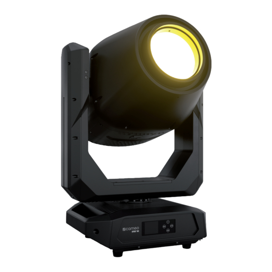
- Page 1 USER‘S MANUAL BEDIENUNGSANLEITUNG MANUEL D‘UTILISATION MANUAL DE USUARIO INSTRUKCJA OBSŁUGI MANUALE D‘USO ANIMATION WHEEL OTOS ® BEAM SPOT WASH HYBRID MOVING HEAD IP65 CLOTOSH5...
-
Page 2: Table Of Contents
CONTENTS / INHALTSVERZEICHNIS / CONTENU / CONTENIDO / TREŚĆ / CONTENUTO ENGLISH INFORMATION ON THIS USER MANUAL INTENDED USE DEFINITIONS AND SYMBOL EXPLANATIONS SAFETY INSTRUCTIONS NOTES ON PORTABLE OUTDOOR DEVICES INCLUDED INTRODUCTION CONNECTIONS, OPERATING AND DISPLAY ELEMENTS OPERATION W-DMX™ STATUS SETUP AND INSTALLATION CARE, MAINTENANCE AND REPAIR REPLACING THE LAMP... - Page 3 LEUCHTMITTEL AUSTAUSCHEN LEUCHTMITTEL JUSTIEREN GOBOS AUSTAUSCHEN ABMESSUNGEN (mm) TECHNISCHE DATEN ERLÄUTERUNGEN ZUR IP-SCHUTZART MINDESTABSTAND ZUR BELEUCHTETEN FLÄCHE MINDESTABSTAND ZU NORMAL ENTFLAMMBAREN MATERIALIEN ENTSORGUNG HERSTELLERERKLÄRUNGEN FRANCAIS INFORMATIONS CONCERNANT CE MANUEL D’UTILISATION UTILISATION CONFORME EXPLICATIONS DES TERMES ET DES SYMBOLES CONSIGNES DE SÉCURITÉ REMARQUES CONCERNANT LES APPAREILS D’EXTÉRIEUR MOBILES CONTENU DE LA LIVRAISON INTRODUCTION...
- Page 4 CONEXIONES, ELEMENTOS DE MANEJO Y ELEMENTOS DE VISUALIZACIÓN FUNCIONAMIENTO ESTADO W-DMX™ INSTALACIÓN Y MONTAJE CUIDADO, MANTENIMIENTO Y REPARACIÓN CAMBIO DE LA LÁMPARA AJUSTE DE LA LÁMPARA CAMBIO DE GOBOS DIMENSIONES (mm) DATOS TÉCNICOS EXPLICACIÓN SOBRE LA CLASE DE PROTECCIÓN IP DISTANCIA MÍNIMA CON RESPECTO A LA SUPERFICIE ILUMINADA DISTANCIA MÍNIMA CON RESPECTO A MATERIALES NORMALMENTE INFLAMABLES ELIMINACIÓN...
- Page 5 ITALIANO SPIEGAZIONE DI CONCETTI E SIMBOLI INDICAZIONI SULLA SICUREZZA AVVERTENZE PER DISPOSITIVI PORTATILI PER ESTERNI VOLUME DI CONSEGNA INTRODUZIONE CONNETTORI, ELEMENTI DI COMANDO E VISUALIZZAZIONE UTILIZZO STATO W-DMX™ INSTALLAZIONE E MONTAGGIO PULIZIA, MANUTENZIONE E RIPARAZIONE SOSTITUZIONE DELLA LAMPADA REGOLAZIONE DELLA LAMPADA SOSTITUZIONE DEI GOBO DIMENSIONI (mm) DATI TECNICI...
-
Page 6: Information On This User Manual
This device has been developed and manufactured to the highest quality standards to ensure many years of problem-free operation. Please read this user manual carefully to be able to use your new Cameo product quickly and optimally. Further information about Cameo Light is avail- able on our website CAMEOLIGHT.COM. -
Page 7: Safety Instructions
This symbol identifies hazards that can cause electric shock. This symbol identifies hazardous areas or hazardous situations. This symbol indicates hazards caused by hot surfaces. This symbol indicates hazards caused by intense light sources. This symbol indicates a device in which there are no user-replaceable parts. This symbol indicates additional information on the operation of the product. - Page 8 ATTENTION: 1. Do not switch on the device if it has been exposed to extreme temperature fluctu- ations (for example, following transport). Moisture and condensation can damage the device. Switch on the device only when it has reached room temperature. 2.
- Page 9 CAUTION: 1. Moving components such as mounting brackets may become jammed. 2. In the case of devices with motor-driven components, there is a risk of injury due to the movement of the device. Sudden movement of the device can cause shock reactions.
- Page 10 SIGNAL TRANSMISSION BY RADIO (e.g. W-DMX or audio radio systems): The quality and performance of wireless signal transmissions generally depends on the ambient conditions. The following factors can impact range and signal stability, for example: • Shielding (e.g. masonry, metal structures, water) •...
-
Page 11: Notes On Portable Outdoor Devices
Please check the completeness and integrity of the delivery and notify your distribution partner immediately after purchase if the delivery is not complete or if it is damaged. Product includes: • OTOS H5 moving head • 1 x power cable • 2 Omega brackets... -
Page 12: Introduction
Connection via supplied power cable (when not in use, always close with rubber sealing cap). POWER OUT IP65 power output socket with rubber sealing cap. Facilitates power supply to other CAMEO spotlights. Ensure that the total current consumption of all connected devices does not exceed the value specified on the device in amperes (A) (when not in use, always close with the rubber sealing cap). - Page 13 DMX IN Male IP65 5-pin XLR socket for connecting a DMX control device (e.g. DMX console; when not in use, always close with the rubber sealing cap). DMX OUT Female IP65 5-pin XLR socket for sending DMX control signal (when not in use, always close with the rubber sealing cap).
- Page 14 UP and DOWN – Select the menu items in the main menu (DMX address, operating mode, etc.) and in the sub-menus using UP and DOWN. Change the status or value in a menu item, e.g. DMX address. ENTER – Press ENTER to access the menu level to make value or status changes, and to access one of the sub-menus.
-
Page 15: Operation
OPERATION NOTES As soon as the spotlight is correctly connected to the mains supply, “Welcome to Cameo”, the model name and the software version will be displayed in succession during the start process and motor reset. After this process, the spotlight is ready for operation and the previously activated operating mode is launched. - Page 16 Standalone operating mode Temperature of the device head W-DMX status Warning Lamp status Scene and signal output Note regarding the main display in operating modes with external control: As soon as the control signal is interrupted, the characters in the centre of the display begin to flash. The flashing stops when a control signal is present.
-
Page 17: W-Dmx™ Status
W-DMX™ STATUS W-DMX W-DMX W-DMX W-DMX W-DMX W-DMX W-DMX W-DMX W-DMX as receiver as receiver as receiver as receiver as trans- as trans- as trans- as trans- deactivated activated, activated activated activated mitter mitter mitter mitter not paired with G3 with G4s with G3 with G4s... - Page 18 DMX OPERATION VIA W-DMX Starting from the main display, press MENU to enter the main menu. Use UP and DOWN to select the Control menu and press ENTER. Now select the menu itemW-DMX and confirm again. See the table below for information on the sub-menu items in the W-DMX menu and the relevant setting options.
- Page 19 Slave Receive Signal reception exclusively via DMX IN XLR Only Mode reception Signal reception via DMX IN, with signal interruption via XLR First mode W-DMX Signal reception via W-DMX, with signal interruption via Wireless First DMX IN Signal reception exclusively via W-DMX Wireless Only Wireless Disconnect all connections and place in pairing standby mode...
- Page 20 Dimmer 000 – 255 Master dimmer 0% -> 100% Dimmer Fine 000 – 255 Master dimmer fine 0% -> 100% Strobe 000 – 255 Multi-functional strobe Cyan 000 – 255 Cyan Fine 000 – 255 Magenta 000 – 255 Magenta Fine 000 –...
- Page 21 Settings Lamp State Switching off the lamp ATTENTION! Switch- ing off the lamp shortly after switching on is prevented by a delay circuit to protect the lamp (approx. 1 minute)! Do not disconnect the device from the power supply before the switch-off process is complete! Switching on the lamp Default...
- Page 22 Motor Pan Reverse Does not reverse pan direction Reverses pan direction Tilt Reverse Does not reverse tilt direction Reverses tilt direction Feedback Automatic position correction is disabled Automatic position correction is enabled Colour wheel scroll Continuous rotation of the colour wheels snap Colour wheel jumps directly back to the desired colour filter when the relevant value is reached...
- Page 23 See the table below for information on the sub-menu items in the Info menu. Info Firmware Disp: V1.x.x CTR1-Motor: V1.x.x CTR2-Motor V1.x.x CTR3-Motor V1.x.x CTR4-Motor V1.x.x Temperature Head xxx °C/°F Base xxx °C / °F Fan Speed Display of the xxxx RPM speed of the correspond-...
- Page 24 Service Default values Factory Resets to factory setting User A Resets to User A values (save user values: Settings -> Set def. values) User B Resets to User B values (save user values: Settings -> Set def. values) User C Resets to User C values (save user values: Settings ->...
-
Page 25: Setup And Installation
SETUP AND INSTALLATION Thanks to its integrated rubber feet, the lamp can be positioned in a suitable location on a level surface. Traverse installation can be achieved with the help of two Omega brackets, which are attached to the base of the device (A). 2 x Omega brackets are included. Suitable beam clamps are available as an option. -
Page 26: Care, Maintenance And Repair
CARE, MAINTENANCE AND REPAIR In order to ensure the long-term, proper functioning of the device, it must be regularly cleaned and, if necessary, maintained. The maintenance requirement depends on the intensity of use and the environment in which it is used. We generally recommend a visual inspection before each operation. -
Page 27: Replacing The Lamp
UV filter! In order to maintain the seal of the OTOS H5 moving head according to protection class IP65, a new seal must be inserted at the appropriate location after the lamp has been replaced. - Page 28 5. Disconnect the two cables for power supply to the lamp by disconnecting the plugs at the contacts. 6. Loosen the two screws of the upper bracket approximately one turn and push the spring-load- ed lower bracket downwards. 7. The lamp may now be tilted upwards and pulled downwards out of the retaining frame. 8.
-
Page 29: Calibrating The Lamp
When carrying out any work, make sure that no foreign bodies enter the housing! In order to maintain the seal of the OTOS H5 moving head according to protection class IP65, a new seal must be inserted at the corresponding location after calibrating... - Page 30 If the hotspot is not in the centre of the projection of the light beam, it can be calibrated by means of two adjustment screws. Example: 1. Fully disconnect the spotlight from the mains (pull out the mains plug)! Make sure that the spotlight has cooled down completely! 2.
-
Page 31: Replacing Gobos
5. Use the two calibration screws to centre the hotspot (see markings). 6. Remove the old seal from the groove in the lamp compartment surround. 7. Thoroughly clean the groove and the contact surface of the fan unit. Make sure that the contact surfaces of the seal are free from foreign objects and dirt. - Page 32 In order to maintain the seal of the OTOS H5 moving head according to protection class IP65, a new seal must be inserted at the corresponding location after replacing a gobo. Carefully follow each step in the instructions below. 1. Switch off the lamp (Settings -> Lamp -> State -> Off), then activate a DMX mode and disconnect the spotlight from the DMX control.
- Page 33 6. The gobo can now be removed from the bracket and replaced with another one. 7. Then place the gobo bracket back into the gobo wheel, ensuring that the gobo bracket is correctly seated in the corresponding recess. You can check that the gobo is seated correctly by turning the gobo wheel.
-
Page 34: Dimensions (Mm)
DIMENSIONS (mm) 456,4 456,4 334,7 334,7 456,4 527,8 270,8 OTOSH5 OSH5 Art No. CLOTOSH5 Scale: 1:10 ssumes no responsibility or liability for the correctness, accuracy and completeness of this drawing. | Adam Hall übernimmt keine Gewähr oder Haftung für die Ri Adam Hall assumes no responsibility or liability for the correctness, accuracy and completeness of this drawing. -
Page 35: Technical Data
TECHNICAL DATA PRODUCT NUMBER: CLOTOSH5 Product type: Outdoor Discharge Moving Light Type: Moving Head Number of lamps: Type of lamp: Signify MSD Silver 480 W Lamp operating time Max. 1500 h at rated output: Maximum lamp ser- 3000 h* vice life: Colour temperature Cool white 6800 K (lamp):... - Page 36 PRODUCT NUMBER: CLOTOSH5 Operating voltage: 100–240 V AC / 50–60 Hz Electrical protection class: Power consumption: 700 W Luminous flux of 19,000 lm spotlight: Power supply connec- TRUE1-compatible input and output (output max. 6 A) tion: IP protection class: IP 65 Ambient operating -15°C to 40°C temperature:...
-
Page 37: Explanation Of Ip Protection Class
EXPLANATION OF IP PROTECTION CLASS 1. An IP rating only reflects protection from solid objects and water. It does not describe general weather resistance, such as protection from UV radiation and temperature, etc. 2. The first identification digit indicates protection from dust, solid objects and contact: IP2X Protected against solid foreign bodies ≥... -
Page 38: Disposal
DISPOSAL Packaging: 1. Packaging can be fed into the reusable material cycle using the usual disposal methods. 2. Please separate the packaging in accordance with the disposal laws and recy- cling regulations in your country. Device: 1. This device is subject to the European Directive on Waste Electrical and Electronic Equipment, as amended. -
Page 39: Manufacturer's Declarations
MANUFACTURER’S DECLARATIONS MANUFACTURER’S WARRANTY & LIMITATION OF LIABILITY Adam Hall GmbH, Adam-Hall-Str. 1, 61267 Neu Anspach, Germany / E-mail Info@adamhall.com / +49 (0)6081 / 9419-0. Our current warranty conditions and limitation of liability can be found at: https://cdn-shop.adamhall.com/media/pdf/Manufacturers-Declarations-CAMEO_DE_EN_ES_FR.pdf. Contact your distribution partner for service. UKCA- CONFORMITY Hereby, Adam Hall Ltd. -
Page 40: Deutsch
Dieses Gerät wurde unter hohen Qualitätsanforderungen entwickelt und gefertigt, um viele Jahre einen reibungslosen Betrieb zu gewährleisten. Bitte lesen Sie diese Bedienungsanleitung sorgfäl- tig, damit Sie Ihr neues Produkt von Cameo Light schnell und optimal einsetzen können. Weitere Informationen über Cameo Light erhalten Sie auf unserer Website CAMEOLIGHT.COM. -
Page 41: Sicherheitshinweise
Dieses Symbol kennzeichnet Gefahren, die einen elektrischen Schlag verursachen können. Dieses Symbol kennzeichnet Gefahrenstellen oder gefährliche Situationen. Dieses Symbol kennzeichnet Gefahren durch heiße Oberflächen. Dieses Symbol kennzeichnet Gefahren durch intensive Lichtquellen. Dieses Symbol kennzeichnet ein Gerät, in dem sich keine vom Benutzer austauschbaren Teile befinden. - Page 42 ACHTUNG: 1. Nehmen Sie das Gerät nicht in Betrieb, wenn es starken Temperaturschwankungen ausgesetzt war (beispielsweise nach dem Transport). Feuchtigkeit und Kondensat könnten das Gerät beschädigen. Schalten Sie das Gerät erst ein, wenn es Umge- bungstemperatur erreicht hat. 2. Stellen Sie sicher, dass die Spannung und die Frequenz des Stromnetzes mit den auf dem Gerät angegebenen Werten übereinstimmen.
- Page 43 WARNUNG: 1. Verwenden Sie das Gerät nur in der vorgesehenen Art und Weise. 2. Betreiben Sie das Gerät nur mit dem vom Hersteller empfohlenen und vorgesehenen Zubehör. 3. Beachten Sie bei der Installation die für Ihr Land geltenden Sicherheitsvorschriften. 4. Überprüfen Sie nach dem Anschluss des Geräts alle Kabelwege, um Schäden oder Unfälle, z.
- Page 44 ACHTUNG: 1. Installieren und betreiben Sie das Gerät nicht in der Nähe von Heizkörpern, Wärme- speichern, Öfen oder sonstigen Wärmequellen. Sorgen Sie dafür, dass das Gerät immer so installiert ist, dass es ausreichend gekühlt wird und nicht überhitzen kann. 2. Platzieren Sie keine Zündquellen wie z.B. brennende Kerzen in der Nähe des Geräts.
- Page 45 SIGNALÜBERTRAGUNG PER FUNK (z.B. W-DMX oder Audio-Funksysteme): Die Qualität und Leistungsfähigkeit kabelloser Signalübertragungen ist generell abhängig von den Umgebungsbedingungen. Einfluss auf die Reichweite und Signalstabilität haben z.B.: • Abschirmung (z.B. Mauerwerk, Metallbauten, Wasser) • Hohes Funkaufkommen (z.B. starke W-LAN Netze) •...
-
Page 46: Hinweise Für Ortsveränderliche Outdoor-Geräte
ACHTUNG! Das Abschalten des Leuchtmittels kurz nach dem Einschalten wird durch eine Verzögerungsschaltung zum Schutz des Leuchtmittels verhindert (ca.1 Minute)! Nehmen Sie das Gerät nicht vom Stromnetz, bevor der Abschaltvor- gang abgeschlossen ist! LEUCHTMITTEL Um die einwandfreie Funktion des Geräts zu erhalten, wird empfohlen, das Leucht- mittel nach spätestens 1500 Stunden Betriebszeit durch qualifiziertes Service-Per- sonal auszutauschen. -
Page 47: Lieferumfang
Bitte überprüfen Sie die Vollständigkeit und Unversehrtheit der Lieferung und benachrichtigen Sie Ihren Vertriebspartner bitte unverzüglich nach dem Kauf, falls die Lieferung nicht komplett oder beschädigt ist. Im Lieferumfang des Produkts sind enthalten: • OTOS H5 Moving Head • 1 Netzkabel • 2 Omega-Bügel • Bedienungsanleitung EINFÜHRUNG... -
Page 48: Anschlüsse, Bedien- Und Anzeigeelemente
60Hz. Anschluss mit Hilfe des mitgelieferten Netzkabels (bei Nichtgebrauch stets mit der Gummidichtkappe verschließen). POWER OUT IP65 Netzausgangsbuchse mit Gummidichtkappe. Dient der Netzversorgung weiterer CAMEO Scheinwerfer. Achten Sie darauf, dass die gesamte Stromaufnahme aller angeschlossenen Geräte den auf dem Gerät in Ampere (A) angegebenen Wert nicht überschreitet (bei Nichtgebrauch stets mit der Gummidichtkappe verschließen). - Page 49 ACHTUNG: Um den Spritzwasserschutz nach Schutzklasse IP65 bei den DMX-Buchsen zu gewährleisten, müssen die speziellen DMX Eingangs- und Ausgangsbuchsen korrekt mit den IP65 Spezial-XLR-Steckern verschlossen sein, bzw. die Gummidichtkappen zum Verschließen verwendet werden. Die Netzbuchsen POWER IN und POWER OUT sind in korrekt gestecktem Zustand spritzwassergeschützt nach IP65, ebenso bei korrekter Verwendung der Gummidichtkappen.
-
Page 50: Bedienung
HINWEISE Sobald der Scheinwerfer korrekt am Stromnetz angeschlossen ist, wird während des Startvorgangs und des Motoren-Resets „Welcome to Cameo“, die Modellbezeichnung und die Softwareversion im Display angezeigt. Nach diesem Vorgang ist der Scheinwerfer betriebsbereit und die Betriebsart, die zuvor aktiviert war, wird gestartet. - Page 51 DISPLAY HAUPTANZEIGE Die Display Hauptanzeige zeigt in den verschiedenen Betriebsarten unterschiedliche, Betriebsart relevante Informationen an. Betriebsarten DMX und W-DMX Temperatur des Gerätekopfs W-DMX Status Warnmeldung Leuchtmittelstatus DMX-Startadresse und DMX-Modus Betriebsart Slave Temperatur des Gerätekopfs W-DMX Status Warnmeldung Leuchtmittelstatus Betriebsart...
- Page 52 Stand Alone Betriebsart Temperatur des Gerätekopfs W-DMX Status Warnmeldung Leuchtmittelstatus Szene und Signalausgabe Hinweis zur Hauptanzeige in den Betriebsarten mit externer Steuerung: Sobald das Steuer-Signal unterbrochen wird, beginnen die Zeichen in der Mitte des Displays zu blinken, liegt das Steuer-Signal wieder an, stoppt das Blinken. Warnmeldung: Erscheint das Warnsymbol (Dreieck mit Ausrufezeichen) im Display, liegt bei einer oder mehreren Komponenten des Geräts ein Fehler vor.
-
Page 53: W-Dmx™ Status
W-DMX™ STATUS W-DMX W-DMX W-DMX W-DMX W-DMX W-DMX W-DMX W-DMX W-DMX als Receiver als Receiver als Receiver als Receiver als Trans- als Trans- als Trans- als Trans- deaktiviert aktiviert, aktiviert und aktiviert aktiviert mitter mitter mitter mitter nicht gekoppelt, mit G3 mit G4s mit G3 mit G4s... - Page 54 DMX-BERTRIEB VIA W-DMX Ausgehend von der Hauptanzeige gelangen Sie durch Drücken auf MENU in das Hauptmenü (Main Menu). Wählen Sie mit Hilfe von UP und DOWN das Kontrollmenü Control aus und drücken auf ENTER. Wählen Sie nun den Menüpunkt W-DMX aus und bestätigen abermals. Informationen zu den Untermenüpunkten im W-DMX-Menü...
- Page 55 Informationen zu den Untermenüpunkten im Slave-Menü und den entsprechenden Einstell- optionen finden Sie in untenstehender Tabelle. Slave Receive Emp- Signalempfang ausschließlich via DMX IN XLR Only Mode fangsart Signalempfang via DMX IN, bei Signalunterbrechung via XLR First einstellen W-DMX Signalempfang via W-DMX, bei Signalunterbrechung via Wireless First DMX IN Signalempfang ausschließlich via W-DMX...
- Page 56 Edit Scene - 255 0% -> 100% Pan Fine - 255 0% -> 100% Tilt - 255 0% -> 100% Tilt Fine - 255 0% -> 100% Dimmer - 255 Master dimmer 0% -> 100% Dimmer Fine - 255 Master dimmer fine 0% -> 100% Strobe - 255 Multifunctional Strobe Cyan...
- Page 57 SYSTEMEINSTELLUNGEN (Settings) Ausgehend von der Hauptanzeige gelangen Sie durch Drücken auf MENU in das Hauptmenü (Main Menu). Wählen Sie mit Hilfe von UP und DOWN Settings aus und drücken auf ENTER. Informationen zu den Untermenüpunkten im Settings-Menü und den entsprechenden Einstell- optionen finden Sie in untenstehender Tabelle.
- Page 58 Dimmer Curve Linear Die Lichtintensität steigt linear mit dem DMX-Wert Exponential Die Lichtintensität lässt sich im unteren DMX-Wertbereich fein und im oberen DMX-Wert- bereich grob einstellen Logarithmic Die Lichtintensität lässt sich im unteren DMX-Wertbereich grob und im oberen DMX-Wert- bereich fein einstellen S-Curve Die Lichtintensität lässt sich im unteren und oberen DMX-Wertbereich fein und im mittleren...
- Page 59 SYSTEMINFORMATIONEN (Info) Ausgehend von der Hauptanzeige gelangen Sie durch Drücken auf MENU in das Hauptmenü (Main Menu). Wählen Sie mit Hilfe von UP und DOWN Info aus und drücken auf ENTER. Informationen zu den Untermenüpunkten im Info-Menü finden Sie in untenstehender Tabelle. Info Firmware Disp:...
- Page 60 SERVICE-MENÜ (Service) Ausgehend von der Hauptanzeige gelangen Sie durch Drücken auf MENU in das Hauptmenü (Main Menu). Wählen Sie mit Hilfe von UP und DOWN Service aus und drücken auf ENTER. Informationen zu den Untermenüpunkten im Service-Menü und den entsprechenden Optionen finden Sie in untenstehender Tabelle.
-
Page 61: Aufstellung Und Montage
QUICKLIGHT Stellen Sie eine Szene mit den Basisfunktionen des Moving Heads ohne externen Controller schnell und unkompliziert ein. Ausgehend von der Hauptanzeige gelangen Sie durch Drücken auf MENU in das Hauptmenü (Main Menu). Wählen Sie mit Hilfe von UP und DOWN Quicklight aus und drücken auf ENTER. -
Page 62: Pflege, Wartung Und Reparatur
PFLEGE, WARTUNG UND REPARATUR Um die einwandfreie Funktion des Geräts auf Dauer zu gewährleisten, muss es regelmäßig gepflegt und bei Bedarf gewartet werden. Der Pflege- bzw. Wartungsbedarf steht in Abhängigkeit der Nutzungsintensität und -umgebung. Wir empfehlen generell eine Sichtprüfung vor jeder Inbetriebnahme. Weiterhin empfehlen wir alle 500 Betriebsstunden, oder bei geringerer Nutzungsintensität spätestens nach Ablauf eines Jahres alle unten genannten und zutreffenden Pflegemaßnahmen durchzuführen. - Page 63 1. Gehäuseoberflächen müssen mit einem sauberen, feuchten Tuch gereinigt werden. Dabei ist darauf zu achten, dass keine Feuchtigkeit in das Gerät eindringen kann. 2. Luft Ein- und Austrittsöffnungen müssen regelmäßig von Staub und Schmutz befreit werden. Im Fall des Einsatzes von Druckluft ist darauf zu achten, dass Beschädigungen am Gerät verhindert werden (z.B.
-
Page 64: Leuchtmittel Austauschen
Gerät mit fehlendem oder beschädigtem UV-Filter in Betrieb genommen wird, besteht unmittelbare Verletzungsgefahr! Um die Dichtheit des OTOS H5 Moving Heads nach Schutzart IP65 zu erhalten, muss nach dem Leuchtmitteltausch an der entsprechenden Stelle eine neue Dichtung eingesetzt werden. Beachten Sie dabei präzise jeden Schritt in der nachstehenden Anleitung. - Page 65 4. Lösen Sie die 4 Innensechskantschrauben, die die Lüftereinheit am Scheinwerferkopf halten (siehe Markierungen) und hängen sie vorsichtig ins Sicherungsseil. Achten Sie dabei darauf, dass die Zuleitungen nicht beschädigt werden. 5. Ziehen Sie die beiden Kabel für die Spannungsversorgung des Leuchtmittels an den Steckern von den Kontakten.
-
Page 66: Leuchtmittel Justieren
Achten Sie bei allen Arbeiten darauf, dass keine Fremdkörper in das Gehäuse gelangen! Um die Dichtheit des OTOS H5 Moving Heads nach Schutzart IP65 zu erhalten, muss nach dem Justieren des Leuchtmittels an der entsprechenden Stelle eine neue Dichtung eingesetzt werden. Beachten Sie dabei präzise jeden Schritt in der nach-... - Page 67 Falls der Hotspot in der Projektion des Lichtstrahls nicht in der Mitte liegt, kann mit Hilfe von zwei Justierschrauben nachjustiert werden. Beispiel: 1. Trennen Sie den Scheinwerfer allpolig vom Stromnetz (Netzstecker ziehen)! Stellen sie sicher, dass der Scheinwerfer vollständig abgekühlt ist! 2.
- Page 68 5. Verwenden Sie die beiden Justierschrauben (siehe Markierungen), um den Hotspot in die Mitte zu bringen. 6. Nehmen Sie die alte Dichtung aus der Nut in der Leuchtmittelfachumrandung. 7. Reinigen Sie die Nut und die Auflagefläche der Lüftereinheit gründlich. Stellen Sie sicher, dass die Auflageflächen der Dichtung frei von Fremdkörpern und Verunreinigungen sind.
-
Page 69: Gobos Austauschen
Gobohalter eingesetzt werden, da sonst Hitzeschäden an den Gobos und den Gobohaltern entstehen können! Um die Dichtheit des OTOS H5 Moving Heads nach Schutzart IP65 zu erhalten, muss nach dem Austauschen eines Gobos an der entsprechenden Stelle eine neue Dichtung eingesetzt werden. Beachten Sie dabei präzise jeden Schritt in der nachstehenden Anleitung. - Page 70 4. Legen Sie das Modul mit den Farb- und Goborädern nach oben gerichtet auf eine saubere und ebene Unterlage. Drehen Sie den Ausschnitt „Open“ des Goborads mit den fixen Gobos manuell nach vorne und danach das Goborad mit den austauschbaren Gobos so lange, bis das gewünschte Gobo in dem Ausschnitt „Open“...
- Page 71 11. Nehmen Sie die neue Dichtung aus der Verpackung und entfernen Sie eventuelle Rückstände des Formtrennmittels. 12. Legen Sie nun die Dichtung formschlüssig in die Nut. Achten Sie darauf, dass die Dichtung nicht in sich verdreht ist. 13. Setzen Sie die Abdeckung plan auf die Dichtung in der Einbauschachtumrandung. 14.
-
Page 72: Abmessungen (Mm)
ABMESSUNGEN (mm) 456,4 456,4 334,7 334,7 456,4 527,8 270,8 OTOSH5 OSH5 Art No. CLOTOSH5 Scale: 1:10 ssumes no responsibility or liability for the correctness, accuracy and completeness of this drawing. | Adam Hall übernimmt keine Gewähr oder Haftung für die Ri Adam Hall assumes no responsibility or liability for the correctness, accuracy and completeness of this drawing. -
Page 73: Technische Daten
TECHNISCHE DATEN ARTIKELNUMMER: CLOTOSH5 Produktart: Outdoor Discharge Moving Light Typ: Moving Head Anzahl Leuchtmittel: Typ Leuchtmittel: Signify MSD Silver 480W Bertriebszeit Max. 1500 h Leuchtmittel bei Nennleistung: Maximale Lebens- 3000 h* dauer Leuchtmittel: Farbtemperatur Kaltweiß 6800K (Leuchtmittel): Farbmischfunktion: Farbwiedergabe High CRI Filter ≥80 Farbrad Anzahl Farben: 15 + offen und kontiniuerliches Positionieren Anzahl Gobos: 27 + offen (19 fix + 8 rotierend) - Page 74 ARTIKELNUMMER: CLOTOSH5 Betriebsspannung: 100 – 240V AC / 50 – 60Hz Elektrische Schutzklasse: Leistungsaufnahme: 700W Lichtstrom 19000lm Scheinwerfer: Stromversorgungsan- TRUE1 kompatibler Ein- und Ausgang (Ausgang max. 6A) schluss: IP-Schutzart: IP 65 Umgebungstemperatur -15°C – 40°C in Betrieb: Gehäusematerial: Aluminiumlegierung Druckguß Gehäusefarbe: schwarz Gehäusekühlung:...
-
Page 75: Erläuterungen Zur Ip-Schutzart
ERLÄUTERUNGEN ZUR IP-SCHUTZART 1. Eine IP-Schutzart gibt ausschließlich den Schutz gegen feste Gegenstände, sowie Wasser wie- der. Sie beschreibt keine allgemeine Witterungsbeständigkeit, wie beispielsweise Schutz gegen UV-Strahlung und Temperatureinflüsse etc.. 2. Die erste Kennziffer bezeichnet den Schutz gegen Staub, feste Gegenstände und Berührung: IP2X Geschützt gegen feste Fremdkörper mit Durchmesser ≥... -
Page 76: Entsorgung
ENTSORGUNG Verpackung: 1. Verpackungen können über die üblichen Entsorgungswege dem Wertstoffkreislauf zugeführt werden. 2. Bitte trennen Sie die Verpackung entsprechend der Entsorgungsgesetze und Wertstoffverordnungen in Ihrem Land. Gerät: 1. Dieses Gerät unterliegt der europäischen Richtlinie für Elektro- und Elektronik-Altgeräte in der jeweils geltenden aktuellen Fassung. WEEE-Richtlinie Waste Electrical and Electronical Equipment. -
Page 77: Herstellererklärungen
HERSTELLERERKLÄRUNGEN HERSTELLERGARANTIE & HAFTUNGSBESCHRÄNKUNG Adam Hall GmbH, Adam-Hall-Str. 1, D-61267 Neu Anspach / E-Mail Info@adamhall.com / +49 (0)6081 / 9419-0. Unsere aktuellen Garantiebedingungen und Haftungsbeschränkung finden Sie unter: https://cdn-shop.adamhall.com/media/pdf/Manufacturers-Declarations-CAMEO_DE_EN_ES_FR.pdf. Im Servicefall wenden Sie sich an Ihren Vertriebspartner. CE-KONFORMITÄT Hiermit erklärt die Adam Hall GmbH, dass dieses Produkt folgender Richtlinie entspricht (soweit zutreffend): Niederspannungsrichtlinie (2014/35/EU) EMV-Richtlinie (2014/30/EU) -
Page 78: Francais
Cet appareil a été conçu et produit suivant des exigences de qualité très strictes pour fonctionner pendant de nombreuses années. Veuillez lire attentivement ce manuel d’utilisation pour pouvoir utiliser rapidement et de manière optimale votre nouveau produit Cameo Light. Vous trouverez de plus amples informations sur Cameo Light sur notre site Web CAMEOLIGHT.COM. -
Page 79: Consignes De Sécurité
Ce symbole indique un danger susceptible de provoquer une décharge électrique. Ce symbole indique une zone ou une situation dangereuse. Ce symbole indique des dangers liés à des surfaces chaudes. Ce symbole signale des dangers liés à des sources lumineuses intenses. Ce symbole indique que l’appareil ne contient aucune pièce remplaçable par l’utilisateur. - Page 80 ATTENTION : 1. Ne mettez pas immédiatement l’appareil en service s’il a été exposé à d’impor- tantes variations de température (par exemple après le transport). L’humidité et la condensation risquent d’endommager l’appareil. Ne mettez l’appareil en marche que lorsqu’il est à température ambiante. 2.
- Page 81 AVERTISSEMENT : 1. Utilisez uniquement cet appareil conformément à l’usage prévu. 2. Utilisez uniquement cet appareil avec les accessoires recommandés et prévus par le fabricant. 3. Lors de l’installation, veillez à respecter les prescriptions de sécurité en vigueur dans votre pays. 4.
- Page 82 ATTENTION : 1. N’installez et n’utilisez pas cet appareil à proximité de radiateurs, d’accumulateurs thermiques, de fours ou d’autres sources de chaleur. Veillez à installer l’appareil de façon à assurer en permanence un refroidissement suffisant et à éviter une surchauffe. 2. Ne placez pas de sources d’ignition à proximité de l’appareil, telles que des bou- gies allumées.
- Page 83 TRANSMISSION DE SIGNAUX PAR RADIO (par ex. W-DMX ou systèmes audio sans fil) : La qualité et la performance des transmissions de signaux sans fil dépendent généralement des conditions ambiantes. Les éléments suivants ont par exemple une influence sur la portée et la stabilité des signaux : •...
- Page 84 TRANSMISSION DE SIGNAL PAR W-DMX AVERTISSEMENT : En règle générale, la transmission DMX sans fil ne doit pas être utilisée pour des applications présentant des facteurs de sécurité susceptibles d’en- traîner des dommages corporels ou matériels en cas de défaillance. Ceci s’applique en particulier aux structures de scènes ou de traverses mobiles, aux moteurs/dispositifs de levage commandés par DMX ou aux dispositifs de levage destinés au fonctionnement de monte-plateaux, de systèmes hydrauliques ou de composants mobiles similaires fonctionnant en mode DMX.
-
Page 85: Remarques Concernant Les Appareils D'extérieur Mobiles
Veuillez vérifier que la livraison est complète et qu’il n’y a aucun dommage ; dans le cas contraire, informez votre revendeur immédiatement après l’achat. Contenu de la livraison : • Lyre OTOS H5 • 1 câble d’alimentation • 2 étriers oméga • Manuel d’utilisation INTRODUCTION LYRE À... -
Page 86: Raccordements, Éléments De Commande Et D'affichage
Embase secteur de sortie IP65 avec cache en caoutchouc. Permet d’alimenter d’autres pro- jecteurs CAMEO. Assurez-vous que la consommation totale de tous les appareils connectés ne dépasse pas la valeur en ampères (A) indiquée sur l’appareil (mettre systématiquement le cache étanche en caoutchouc si raccord non utilisé). - Page 87 ANTENNE Antenne pour la commande via W-DMX™. DISPOSITIF DE COMPENSATION DE PRESSION Dispositif permettant d’éviter la formation de condensation à l’intérieur de l’appareil. Pour assurer le bon fonctionnement de ce dispositif, il convient de le protéger contre un éventuel encrasse- ment.
- Page 88 PAN LOCK (VERROUILLAGE PANORAMIQUE) Dispositif de verrouillage mécanique pour empêcher la rotation de la tête sur le plan horizontal lors du transport. LOCK UNLOCK Débranchez l’appareil du secteur, orientez la tête de sorte qu’elle soit parallèle à la base (4 positions possibles) et appuyez sur le levier de blocage en direction de l’axe de rotation Pan pour procéder au verrouillage (LOCK).
-
Page 89: Utilisation
Dès que le projecteur est correctement raccordé à l’alimentation secteur, un message de bienve- nue (« Welcome to Cameo »), la désignation du modèle et la version du logiciel s’affichent succes- sivement à l’écran pendant la phase de démarrage et de réinitialisation du moteur. Le projecteur est ensuite opérationnel et le mode de fonctionnement précédemment activé... - Page 90 Mode de fonctionnement Slave Température de la tête de l’appareil État W-DMX Message d’avertissement État de l’ampoule Mode de fonctionnement Mode de fonctionnement Stand Alone Température de la tête de l’appareil État W-DMX Message d’avertissement État de l’ampoule Scène et sortie de signal Remarque concernant l’affichage principal dans les modes de fonctionnement avec pilotage externe : si le signal de pilotage est interrompu, les caractères au centre de l’écran se...
-
Page 91: État W-Dmx
W-DMX™ Pour coupler un récepteur W-DMX à un émetteur compatible W-DMX, il est nécessaire d’exécuter la commande Reset dans l’option de menu W-DMX sous Receiver (sélectionner Reset et vali- der). Le récepteur est maintenant prêt pour le couplage et attend la demande de couplage d’un émetteur. - Page 92 DMX Address Réglage de l’adresse DMX de départ 001 – 486 Mode Sélection du mode DMX 26CH Standard 32CH Extended W-DMX Désactiver la transmission du signal de commande DMX Transmitter via W-DMX Activer la transmission du signal de commande DMX via W-DMX Couplage avec des appareils W-DMX prêts à...
- Page 93 MODE SLAVE À partir de l’écran principal, appuyez sur MENU pour accéder au menu principal (Main Menu). Utilisez les touches UP et DOWN pour sélectionner le panneau de commande Control et appuyez sur ENTER. Sélectionnez ensuite l’option de menu Slave et validez à nouveau. Reliez les unités Slave et Master (même modèle, même version de logiciel) à...
- Page 94 Les informations sur les options de sous-menu du menu Scenes et les options de réglage corres- pondantes sont disponibles dans le tableau ci-dessous. Stand Alone (Scenes) Run Scene Démarrer la scène Scene 1 – 8 Record Scene Enregistrer la scène depuis un contrôleur externe Scene 1 –...
- Page 95 PrismWheel 2 - 255 Prism Wheel 2 Frost - 255 0 % -> 100 % Animation - 255 0 % -> 100 % Animation Rot. - 255 Animation Wheel rotation P/T Macro - 255 Pan / Tilt Macro P/T Speed - 255 Pan / Tilt Macro speed PARAMÈTRES DU SYSTÈME (Settings) À...
- Page 96 Dimmer Curve Linear L’intensité lumineuse augmente de façon linéaire avec la valeur DMX Exponential L’intensité lumineuse peut être réglée de façon précise dans la plage de valeurs DMX inférieure et de façon approximative dans la plage de valeurs DMX supérieure Logarithmic L’intensité...
- Page 97 Miscella- Auto Lock Verrouillage automatique des éléments de com- neous mande désactivé Verrouillage automatique des éléments de commande au bout d’env. 1 minute d’inactivité. Déverrouillage : Appuyez simultanément sur UP et DOWN pendant environ 5 secondes Signal Fail Hold La dernière commande est maintenue lorsque le signal de commande est interrompu Blackout Blackout immédiat lorsque le signal de commande...
- Page 98 Runtime Total xxxx h : xx m Temps de fonctionnement total Lamp xxxx h : xx m Temps de fonctionnement de la lampe Service xxxx h : xx m Durée de fonctionnement après date d’entretien RDM-UID RDM Unique Identifier (identifiant unique) Show DMX Values Affichage des valeurs DMX présentes Error-Info...
-
Page 99: Installation Et Montage
Reset Runtime Service No Ne pas réinitialiser la durée de fonctionnement Réinitialiser la durée de fonctionnement Lamp Ne pas réinitialiser le temps de fonctionnement de la lampe Réinitialiser le temps de fonctionnement de la lampe Password Uniquement à des fins de maintenance QUICKLIGHT Configurez une scène rapidement et facilement à... -
Page 100: Entretien, Maintenance Et Réparation
d’effectuer vous-même l’installation, mais faites appel à une entreprise professionnelle. Des appareils mal montés et mal fixés risquent de se détacher et de tomber. Cela peut causer des blessures graves, voire mortelles. ENTRETIEN, MAINTENANCE ET RÉPARATION Pour garantir le bon fonctionnement de l’appareil à long terme, l’entretien et, si nécessaire, la maintenance doivent être effectués régulièrement. - Page 101 1. Les surfaces du boîtier doivent être nettoyées avec un chiffon propre et humide. Veillez à ce qu’aucune humidité ne pénètre dans l’appareil. 2. Les orifices d’entrée et de sortie d’air doivent être nettoyés régulièrement pour éliminer la poussière et les impuretés. En cas d’utilisation d’air comprimé, veillez à ce que l’appareil ne soit pas endommagé...
- Page 102 UV endommagée est interdite ! Si l’appareil est mis en service sans filtre UV ou avec un filtre endommagé, il existe un risque immédiat de blessure ! Pour maintenir l’étanchéité de la lyre OTOS H5 selon l’indice de protection IP65, un nouveau joint doit être installé à l’endroit correspondant après le remplacement de l’ampoule.
- Page 103 7. L’ampoule peut maintenant être basculée vers le haut et retirée du cadre-support par le bas. 8. Placez la nouvelle ampoule dans le cadre-support dans le même sens. Veillez à ce que le support inférieur à ressort se trouve à nouveau en position de maintien et resserrer les deux vis du support supérieur.
-
Page 104: Régler L'ampoule
Lors de tous les travaux, veillez à ce qu’aucun corps étranger ne pénètre dans le boîtier ! Pour maintenir l’étanchéité de la lyre OTOS H5 selon l’indice de protection IP65, un nouveau joint doit être installé à l’endroit correspondant après le réglage de l’ampoule. - Page 105 4. Desserrez les 4 vis à six pans creux argentées qui maintiennent l’unité de ventilation sur la tête du projecteur (voir les repères) et accrochez-la avec précaution au câble de sécurité. Veillez à ne pas endommager les câbles d’alimentation. 5. Utilisez les deux vis de réglage (voir les repères) pour diriger le faisceau lumineux vers le centre.
-
Page 106: Remplacer Les Gobos
être endommagés par la chaleur. Pour maintenir l’étanchéité de la lyre OTOS H5 selon l’indice de protection IP65, un nouveau joint doit être installé à l’endroit correspondant après le remplacement d’un gobo. - Page 107 4. Posez le module sur une surface propre et plane, les roues de couleurs et de gobos orien- tées vers le haut. Tournez manuellement la découpe « Open » de la roue de gobos fixes vers l’avant, puis la roue de gobos interchangeables jusqu’à ce que le gobo souhaité apparaisse dans la découpe « Open »...
- Page 108 7. Replacez ensuite le support de gobo dans la roue de gobos en veillant à ce que le support de gobos soit correctement inséré dans l’encoche correspondante. Vous pouvez vérifier que le gobo est bien en place en tournant la roue du gobo. Le gobo doit tourner sans accrocher. 8.
-
Page 109: Dimensions (Mm)
DIMENSIONS (mm) 456,4 456,4 334,7 334,7 456,4 527,8 270,8 OTOSH5 OSH5 Art No. CLOTOSH5 Scale: 1:10 ssumes no responsibility or liability for the correctness, accuracy and completeness of this drawing. | Adam Hall übernimmt keine Gewähr oder Haftung für die Ri Adam Hall assumes no responsibility or liability for the correctness, accuracy and completeness of this drawing. -
Page 110: Caractéristiques Techniques
CARACTÉRISTIQUES TECHNIQUES RÉFÉRENCE : CLOTOSH5 Catégorie de produit : Lyre à décharge extérieure Type : Lyre Nombre de lampes : Type de lampe : Signify MSD Silver 480 W Durée de fonctionne- Max. 1500 h ment des ampoules à la puissance nominale : Durée de vie maximale 3000 h* des ampoules : Température Blanc froid 6800 K... - Page 111 RÉFÉRENCE : CLOTOSH5 Réglages du système : Basculement de l’écran, lampe ON/OFF, éclairage de l’écran On/Off, défaillance du signal, basculement Pan, basculement Tilt, feedback, blackout en cas de mouvement, test, réinitialisation, valeurs par défaut de l’utilisateur, fonctions de blackout, défilement/immobilisation de la roue de couleurs/de gobos, verrouillage automatique, vitesse Pan/Tilt, panne de la lampe, mode de la lampe Pilotage :...
-
Page 112: Explications Relatives À L'indice De Protection Ip
*Définition de la durée de vie : le moment où 50 % des lampes sont encore en service et émet- tent au moins 50 % de la puissance lumineuse initiale. EXPLICATIONS RELATIVES À L’INDICE DE PROTECTION IP 1. L’indice de protection IP est uniquement le reflet de la protection contre les corps solides et l’e- au. -
Page 113: Distance Minimale Par Rapport Aux Matériaux Normalement Inflammables
DISTANCE MINIMALE PAR RAPPORT AUX MATÉRIAUX NORMALEMENT INFLAMMABLES Ce symbole indique la distance minimale en mètres (m) à respecter entre l’appareil 0,5 m et des matériaux normalement inflammables. Dans cet exemple, la distance est de 0,5 m. ÉLIMINATION Emballage : 1. Les emballages peuvent être introduits dans le circuit de recyclage par les voies de collecte habituelles. -
Page 114: Déclarations Du Fabricant
DÉCLARATIONS DU FABRICANT GARANTIE DU FABRICANT ET LIMITATION DE RESPONSABILITÉ Adam Hall GmbH, Adam-Hall-Str. 1, D-61267 Neu Anspach / E-mail Info@adamhall.com / +49 (0)6081 / 9419-0. Vous trouverez nos conditions de garantie et nos clauses de limitation de responsabilité actuelles sur Internet à... -
Page 115: Español
Este equipo ha sido desarrollado y fabricado según estrictos criterios de calidad con el fin de garantizar muchos años de funcionamiento perfecto. Lee atentamente el presente manual de instrucciones para poder usar rápidamente y de forma óptima tu nuevo producto de Cameo Light. Puedes encontrar más información sobre Cameo Light en nuestro sitio web CAMEOLIGHT.COM. -
Page 116: Instrucciones De Seguridad
Este símbolo indica peligros que pueden causar una descarga eléctrica. Este símbolo indica puntos de peligro o situaciones peligrosas. Este símbolo indica peligros por la existencia de superficies calientes. Este símbolo indica peligros debido a fuentes de luz intensas. Este símbolo indica que en el equipo no hay piezas que pueda sustituir el usuario. Este símbolo identifica información complementaria sobre el uso del producto. - Page 117 ATENCIÓN: 1. No poner en marcha el equipo si ha estado sometido a fuertes fluctuaciones de temperatura (por ejemplo, tras su transporte). La humedad y el agua condensada pueden dañar el equipo. Encender el equipo únicamente después de que su tem- peratura haya alcanzado la temperatura ambiente.
- Page 118 ADVERTENCIA: 1. Utilizar el equipo únicamente de la forma prevista. 2. Utilizar el equipo solo con los accesorios previstos y recomendados por el fabrican- 3. Durante la instalación, hay que tener en cuenta los reglamentos de seguridad vigen- tes en tu país. 4.
- Page 119 ATENCIÓN: 1. No instalar ni poner a funcionar el equipo cerca de radiadores, acumuladores tér- micos, hornos u otras fuentes de calor. Asegurarse de que el equipo siempre esté instalado de modo que reciba suficiente refrigeración y no pueda sobrecalentarse. 2.
- Page 120 TRANSMISIÓN DE SEÑALES POR RADIO (por ejemplo, W-DMX o sistemas de audio inalámbricos): La calidad y el rendimiento de las transmisiones inalámbricas de señales dependen, por lo general, de las condiciones ambientales. Elementos que influyen en el alcance y la estabilidad de la señal: •...
-
Page 121: Indicaciones Para Equipos Portátiles De Exterior
¡ATENCIÓN! La desconexión del dispositivo luminoso poco después de la conexión se evita mediante una conexión retardada para proteger la lámpara (aprox. 1 minuto). No desconectes el equipo de la red eléctrica hasta que haya finalizado el proceso de apagado. LÁMPARA Para mantener el buen funcionamiento del aparato, se recomienda cambiar la lámpa- ra tras 1500 horas de funcionamiento como máximo por parte de personal de servicio cualificado. -
Page 122: Volumen De Suministro
En el volumen de suministro del producto se incluye: • Cabeza móvil OTOS H5 • 1 cable de alimentación • 2 soportes de montaje Omega •... -
Page 123: Conexiones, Elementos De Manejo Y Elementos De Visualización
Toma de salida de alimentación IP65 con tapa de sellado de goma. Sirve para alimentar otros focos CAMEO. Asegúrate de que el consumo de corriente total de todos los dispositivos conecta- dos no supere el valor indicado en amperios (A) sobre el dispositivo (mientras no se vaya a usar, mantenerla siempre cerrada con la tapa de sellado de goma). - Page 124 ATENCIÓN: Para garantizar la protección contra salpicaduras de los conectores DMX conforme a la clase de protección IP65, las tomas de entrada y salida DMX especiales deberán quedar bien cerradas con los conectores XLR especiales con clase de protec- ción IP65 o utilizar las tapas de sellado de goma para su cierre. Los conectores de alimentación POWER IN y POWER OUT estarán protegidos contra salpicaduras conforme a la clase de protección IP65 tanto si se conectan debidamente como si se hace un uso correcto de las tapas de sellado de goma.
- Page 125 PAN LOCK Dispositivo de bloqueo mecánico para evitar que la cabeza gire horizontalmente durante el transporte. Desconecta el LOCK UNLOCK equipo de la red eléctrica, coloca la cabeza en paralelo a la base (4 posiciones posibles) y presiona la palanca de bloqueo para bloquear la cabeza en la dirección del eje de giro horizontal (LOCK).
-
Page 126: Funcionamiento
«Welcome to Cameo» (Bienvenidos a Cameo), así como la denominación de modelo y la versión del software. Después de este procedimiento, el foco estará listo para funcionar y se iniciará en el último modo operativo activado. - Page 127 Modo de funcionamiento esclavo Temperatura de la cabeza del equipo Estado W-DMX Mensaje de advertencia Estado de la lámpara Modo operativo Modo operativo autónomo Temperatura de la cabeza del equipo Estado W-DMX Mensaje de advertencia Estado de la lámpara Escena y salida de señal Aviso sobre la pantalla principal en los modos operativos con control externo: En el momento en que se interrumpe la señal de control, los caracteres en el centro de la pantalla...
-
Page 128: Estado W-Dmx
W-DMX™ Para emparejar un receptor W-DMX con un transmisor W-DMX compatible, es necesario ejecutar el comando Reset en la opción Receiver del menú WDMX (selecciona Reset y confirma). Ahora el receptor está listo para el emparejamiento y a la espera de la solicitud de emparejamiento de un transmisor. - Page 129 DMX Address Ajuste de la dirección inicial DMX 001 - 486 Mode Selección del modo DMX 26CH Standard 32CH Extended W-DMX Desactivar la transmisión de la señal de control DMX Transmitter mediante W-DMX Activar la transmisión de la señal de control DMX medi- ante W-DMX Emparejamiento con equipos W-DMX listos para empare- Force to pair...
- Page 130 MODO ESCLAVO Partiendo de la pantalla principal, si pulsas MENU accederás al menú principal. Selecciona el menú Control con los botones UP y DOWN y pulsa ENTER. Selecciona ahora la opción de menú Slave y confirma otra vez. Conecta las unidades esclava y maestra (del mismo modelo, con la misma versión de software) mediante un cable DMX (maestra = DMX OUT;...
- Page 131 Encontrarás información sobre las opciones de submenú en el menú Art-Net+DMX y las opciones de ajuste correspondientes en la siguiente tabla. Stand Alone (Scenes) Run Scene Iniciar escena Scene 1 - 8 Record Scene Grabar escena desde un controlador externo Scene 1 - 8 Edit Scene Editar escena (vea la tabla Edit Scene)
- Page 132 Frost - 255 0% -> 100% Animation - 255 0% -> 100% Animation Rot. - 255 Animation Wheel rotation P/T Macro - 255 Pan / Tilt Macro P/T Speed - 255 Pan / Tilt Macro speed CONFIGURACIÓN DEL SISTEMA (Settings) Partiendo de la pantalla principal, si pulsas MENU accederás al menú...
- Page 133 Dimmer Curve Linear La intensidad luminosa aumentará de forma lineal con el valor DMX Exponential La intensidad luminosa permite un ajuste fino en el rango inferior de valores DMX y un ajuste aproximado en el rango superior de valores DMX Logarithmic La intensidad luminosa podrá...
- Page 134 Dispo- Auto Lock Bloqueo automático de los elementos de manejo siciones desactivados varias Bloqueo automático de los elementos de manejo tras aproximadamente 1 minuto sin introducir valores. Para desbloquear: UP y DOWN simultán- eamente durante aprox. Pulsar 5 segundos Signal Fail Hold Se mantendrá...
- Page 135 Encontrarás información sobre las opciones de submenú en el menú Info en la tabla a continua- ción. Info Firmware Disp: V1.x.x CTR1-Motor: V1.x.x CTR2-Motor: V1.x.x CTR3-Motor: V1.x.x CTR4-Motor: V1.x.x Temperature Head xxx °C/°F Base xxx °C/°F Fan Speed Visualización xxxx RPM de la velo- cidad de los ventiladores...
- Page 136 Encontrarás información sobre las opciones de submenú en el menú Service y las opciones correspondientes en la siguiente tabla. Service Default Values Factory Restablecer la configuración de fábrica User A Restablecimiento a los valores del usuario A (guardar los valores del usuario: Settings -> Set Def. Values) User B Restablecimiento a los valores del usuario B (guardar los valores del usuario: Settings ->...
-
Page 137: Instalación Y Montaje
INSTALACIÓN Y MONTAJE Gracias a los pies de goma integrados, el foco puede instalarse en un lugar adecuado sobre una superficie nivelada. El montaje en travesaño se realiza fijando dos soportes de montaje Omega en la base del equipo (A). El volumen de suministro incluye dos soportes de montaje Omega; las abrazaderas aptas para travesaño se pueden pedir por separado. - Page 138 CUIDADOS (que puede realizar el usuario) ¡ADVERTENCIA! Antes de realizar cualquier tarea para mantener cuidado el equipo, desconectar la alimentación eléctrica y, si es posible, todas las conexiones del equipo. ¡AVISO! Un cuidado inadecuado puede provocar daños en el equipo e incluso su destrucción.
-
Page 139: Cambio De La Lámpara
UV o con uno dañado, existe peligro inmediato de lesiones. Para mantener la estanqueidad de la cabeza móvil OTOS H5 según la clase de protec- ción IP65, se debe colocar una nueva junta en el lugar correspondiente tras el cambio de la lámpara. - Page 140 5. Desconecta ambos cables de alimentación eléctrica de la lámpara separando los conectores de los contactos. 6. Afloja los dos tornillos del soporte superior aproximadamente una vuelta y presiona el soporte inferior con resorte hacia abajo. 7. Ahora se puede inclinar la lámpara hacia arriba y tirar hacia abajo para extraerla del bastidor de fijación.
-
Page 141: Ajuste De La Lámpara
Durante todos los trabajos, asegúrate de que no entren cuerpos extraños en la carcasa. Para mantener la estanqueidad de la cabeza móvil OTOS H5 según la clase de protección IP65, se debe colocar una nueva junta en el lugar correspondiente tras el... - Page 142 En caso de que el punto central en la proyección del haz de luz no quede en el centro, se puede ajustar posteriormente con dos tornillos de ajuste. Ejemplo: 1. Desconecta totalmente el foco de la red eléctrica (desconecta la clavija del enchufe). ¡Asegú- rate de que el foco esté...
-
Page 143: Cambio De Gobos
6. Extrae la junta antigua de la ranura del borde del compartimento de la lámpara. 7. Limpia a fondo la ranura y la superficie de apoyo de la unidad de ventilación. Asegúrate de que no haya cuerpos extraños ni contaminación en las superficies de contacto de la junta. 8. - Page 144 Para mantener la estanqueidad de la cabeza móvil OTOS H5 conforme a la clase de protección IP65, se debe colocar una nueva junta en el lugar correspondiente después de cambiar un gobo. Ten en cuenta cada paso de las instrucciones siguientes.
- Page 145 6. Ahora puedes retirar el gobo del soporte y cambiarlo por otro. 7. A continuación, vuelve a colocar el soporte de gobo en la rueda de gobos y asegúrate de que el soporte de gobos se asiente correctamente en la ranura correspondiente. Puedes com- probar el ajuste correcto girando la rueda de gobos, asegurándote de que el gobo gira sin engancharse.
- Page 146 16. Después del montaje de la cubierta se debe realizar una prueba de estanqueidad. Esto se hace retirando la cubierta trasera del cabezal. Para ello, afloja los 4 tornillos Allen de la cubier- ta trasera de la cabeza, retira la cubierta de la cabeza del foco, suelta el cable de seguridad de la cubierta y colócala a un lado.
-
Page 147: Dimensiones (Mm)
DIMENSIONES (mm) 456,4 456,4 334,7 334,7 456,4 527,8 270,8 OTOSH5 OSH5 Art No. CLOTOSH5 Scale: 1:10 ssumes no responsibility or liability for the correctness, accuracy and completeness of this drawing. | Adam Hall übernimmt keine Gewähr oder Haftung für die Ri Adam Hall assumes no responsibility or liability for the correctness, accuracy and completeness of this drawing. -
Page 148: Datos Técnicos
DATOS TÉCNICOS NÚMERO DE ARTÍCULO: CLOTOSH5 Clase de producto: Cabeza móvil de descarga para exteriores Tipo: Cabeza móvil Número de lámparas: Tipo de lámpara: Signify MSD Silver 480 W Tiempo de funciona- Máx. 1500 h miento de la lámpara con potencia nominal: Vida útil máxima de la 3000 h* lámpara:... - Page 149 NÚMERO DE ARTÍCULO: CLOTOSH5 Configuración del Inversión de pantalla, lámpara ON/OFF, iluminación de pantalla On/Off, sistema: fallo de señal, inversión de giro horizontal, inversión de giro vertical, feed back, apagón de movimiento, test, restablecimiento, valores pre- definidos de usuario, funciones de apagón, movimiento continuo/salto de la rueda de colores/gobos, bloqueo automático, velocidad de giro horizontal/vertical, ajuste por defecto de la lámpara, modo de la lámpara Control:...
-
Page 150: Explicación Sobre La Clase De Protección Ip
Otras características: Cable de alimentación de 1 m con conector compatible TRUE1 y 2 soportes de montaje en omega incluidos en la entrega *Definición de la vida útil: El momento en el que el 50 % de las lámparas aún están en funcio- namiento y tienen al menos el 50 % de la potencia lumínica original. -
Page 151: Distancia Mínima Con Respecto A La Superficie Iluminada
DISTANCIA MÍNIMA CON RESPECTO A LA SUPERFICIE ILUMINADA Este símbolo con indicación de distancia en metros (m) indica la distancia mínima 0,5 m de la lámpara con respecto a la superficie iluminada. En este ejemplo, la distancia es de 0,5 m. DISTANCIA MÍNIMA CON RESPECTO A MATERIALES NORMALMENTE INFLAMABLES Este símbolo con indicación de distancia en metros (m) indica la distancia mínima 0,5 m... -
Page 152: Declaraciones Del Fabricante
DECLARACIONES DEL FABRICANTE GARANTÍA DEL FABRICANTE Y EXENCIÓN DE RESPONSABILIDAD Adam Hall GmbH, Adam-Hall-Str. 1, D-61267 Neu Anspach (Alemania) / Correo electrónico: info@adamhall.com / +49 (0)6081 / 9419-0. Encontrarás las condiciones actuales de la garantía y el texto sobre la exención de responsabili- dad en la siguiente página web: https://cdn-shop.adamhall.com/media/pdf/Manufacturers-Declarations-CAMEO_DE_EN_ES_FR.pdf. -
Page 153: Polski
Należy uważnie przeczytać niniejszą instruk- cję obsługi, aby móc jak najszybciej rozpocząć prawidłową eksploatację nowego urządzenia marki Cameo Light. Więcej informacji o marce Cameo Light można znaleźć na naszej stronie CAMEOLIGHT.COM. INFORMACJE DOTYCZĄCE NINIEJSZEJ INSTRUKCJI OBSŁUGI •... -
Page 154: Zasady Bezpieczeństwa
Ten symbol oznacza zagrożenia, które mogą być przyczyną porażenia prądem elek- trycznym. Ten symbol oznacza niebezpieczne miejsca lub sytuacje. Ten symbol oznacza niebezpieczeństwa związane z gorącymi powierzchniami. Ten symbol oznacza niebezpieczeństwa związane z intensywnym źródłem światła. Ten symbol oznacza urządzenie, w którym nie ma części wymienianych przez użytkownika. - Page 155 UWAGA: 1. Nie używać urządzenia, jeśli było ono narażone na duże wahania temperatury (np. po transporcie). Wilgoć i kondensat mogą uszkodzić urządzenie. Włączyć urządze- nie dopiero wtedy, gdy osiągnie temperaturę otoczenia. 2. Sprawdzić, czy napięcie i częstotliwość sieci elektrycznej są zgodne z parametrami podanymi na urządzeniu.
- Page 156 OSTRZEŻENIE: 1. Używać urządzenia tylko zgodnie z przeznaczeniem. 2. Używać urządzenia wyłącznie z akcesoriami zalecanymi i przewidzianymi przez producenta. 3. Podczas instalacji przestrzegać krajowych przepisów bezpieczeństwa. 4. Po podłączeniu urządzenia należy sprawdzić ułożenie wszystkich kabli, aby unik- nąć szkód lub wypadków spowodowanych np. przez potknięcie. 5.
- Page 157 UWAGA: 1. Nie instalować ani nie eksploatować urządzenia w pobliżu grzejników, akumulato- rów ciepła, pieców ani innych źródeł ciepła. Upewnić się, że urządzenie jest zawsze instalowane w taki sposób, aby zapewnić wystarczające chłodzenie i nie dopuścić do przegrzania. 2. W pobliżu urządzenia nie umieszczać źródeł zapłonu, takich jak zapalone świece. 3.
- Page 158 TRANSMISJA SYGNAŁÓW DROGĄ RADIOWĄ (np. W-DMX lub radiowe systemy audio): Jakość i wydajność transmisji bezprzewodowej zależą głównie od warunków otocze- nia. Na zasięg i stabilność sygnału mają wpływ m.in.: • Ekranowanie (np. mury, konstrukcje metalowe, woda) • Wysokie poziomy emisji fal radiowych (np. silne sieci Wi-Fi) •...
- Page 159 TRANSMISJA SYGNAŁÓW W W-DMX OSTRZEŻENIE: Ogólnie rzecz biorąc, bezprzewodowa transmisja DMX nie może być stosowana, gdy występują czynniki wpływające na bezpieczeństwo, które w przypad- ku awarii mogą spowodować obrażenia osób lub szkody materialne. Dotyczy to w szczególności ruchomych konstrukcji scenicznych lub kratownic, sil- ników/podnośników sterowanych przez DMX lub urządzeń...
-
Page 160: Uwagi Dotyczące Przenośnego Sprzętu Zewnętrznego
Prosimy o sprawdzenie, czy przesyłka jest kompletna i nienaruszona, a w przypadku niekomplet- ności lub uszkodzeń prosimy o natychmiastowe powiadomienie o tym fakcie dystrybutora. W zakres dostawy wchodzą: • Ruchoma głowica OTOS H5 • 1 kabel sieciowy • 2 uchwyty Omega •... -
Page 161: Przyłącza, Elementy Obsługi I Wskaźniki
Podłączanie za pomocą dołączonego kabla sieciowego (nieużywane gniazdo zawsze zabezpieczać gumową zaślepką). POWER OUT Gniazdo wyjściowe IP65 z gumową zaślepką. Źródło zasilania dodatkowych reflektorów CAMEO. Całkowity pobór prądu wszystkich podłączonych urządzeń nie może przekroczyć wartości w amperach (A) podanej na urządzeniu (nieużywane gniazdo zawsze zamykać gumową zaślepką). - Page 162 ELEMENT WYRÓWNUJĄCY CIŚNIENIE Element wyrównujący ciśnienie zapobiega skraplaniu się wody wewnątrz obudowy. W celu za- pewnienia prawidłowego działania element należy chronić przed zabrudzeniem. UWAGA: W celu zapewnienia ochrony gniazd DMX przed wodą rozpryskową zgodnie ze stopniem ochrony IP65 należy prawidłowo zamknąć specjalne gniazda wejściowe i wyjściowe DMX specjalnymi wtyczkami XLR IP65 lub zastosować...
- Page 163 PAN LOCK Mechaniczna blokada zapobiegająca obróceniu się głowicy w poziomie podczas transportu. Odłączyć urządzenie od za- LOCK UNLOCK silania, ustawić głowicę równolegle do podstawy (4 możliwe pozycje) i nacisnąć dźwignię blokującą w celu zatrzaśnięcia w kierunku osi obrotowej (LOCK). Odblokować urządzenie przed jego ponownym użyciem (UNLOCK).
-
Page 164: Obsługa
OBSŁUGA WSKAZÓWKI Po prawidłowym podłączeniu reflektora do sieci zasilania podczas procesu uruchamiania i rese- towania silnika jest wyświetlana następująca sekwencja komunikatów: „Welcome to Cameo”, nazwa modelu oraz wersja oprogramowania. Następnie reflektor jest gotowy do pracy w ostatnio wybranym trybie. Jeśli przez około 30 sekund nie nastąpi wprowadzenie żadnych danych, automatycznie włączy się... - Page 165 Tryb pracy slave Temperatura w głowicy urządzenia Status W-DMX Komunikat ostrzegawczy Stan źródła światła Tryb pracy Tryb pracy standalone Temperatura w głowicy urządzenia Status W-DMX Komunikat ostrzegawczy Stan źródła światła Scena i emisja sygnału Wskazówka dotycząca ekranu głównego w trybach pracy z zewnętrznym sterowaniem: Gdy sygnał...
-
Page 166: Status W-Dmx
W-DMX™ Aby sparować odbiornik W-DMX z nadajnikiem zgodnym ze standardem W-DMX, należy w menu WDMX odbiornika wykonać polecenie Reset (wybrać opcję resetowania i potwierdzić). Odbiornik jest teraz w stanie gotowości do sparowania i czeka na żądanie z nadajnika. Rozpocząć parowa- nie, wybierając łącze w menu nadajnika, i potwierdzić. - Page 167 Informacje na temat pozycji podmenu w menu DMX i odpowiednich opcji ustawień znajdują się w poniższej tabeli. DMX Address Ustawianie adresu startowego DMX 001–486 Mode Wybór trybu DMX 26CH Standard 32CH Extended W-DMX Wyłącz przekazywanie sygnału sterującego DMX przez transmiter W-DMX Włącz przekazywanie sygnału sterującego DMX przez W-DMX...
- Page 168 TRYB SLAVE Rozpoczynając od ekranu głównego, naciśnij MENU, aby wejść do menu głównego (Main Menu). Zgodnie z wcześniejszą instrukcją za pomocą przycisków UP i DOWN wybrać menu sterowania Control i nacisnąć ENTER. Wybierz pozycję menu Slave i ponownie potwierdź. Połącz urządzenia slave i master (tego samego modelu i z tym samym oprogramowaniem) kablem DMX (master = DMX OUT –...
- Page 169 Informacje na temat pozycji podmenu w menu Scenes i odpowiednich opcji ustawień znajdują się w poniższej tabeli. Stand Alone (Scenes) Run Scene Uruchomienie sceny Scene 1–8 Record Scene Nagrywanie sceny z zewnętrznego sterownika Scene 1–8 Edit Scene Edytowanie sceny (patrz tabela Edit Scene) Scene 1–8 Master/Alone Scene jako sygnał...
- Page 170 Gobo 2 000 – 255 Gobo fix Zoom 000 – 255 Narrow -> wide Zoom Fine 000 – 255 Narrow -> wide Focus 000 – 255 0% -> 100% Focus Fine 000 – 255 0% -> 100% PrismWheel 1 000 – 255 Prism Wheel 1 PrismWheel 2 000 –...
- Page 171 Display Reverse Obraz wyświetlacza nie jest obrócony Obrócenie obrazu wyświetlacza o 180° Backlight Stale włączone podświetlenie ekranu Off after 60s Wyłączenie podświetlenia ekranu po ok. 1 minucie bezczynności Dimmer Curve Linear Natężenie światła wzrasta liniowo wraz ze wz- rostem wartości DMX Exponential Natężenie światła można ustawić...
- Page 172 Informac- Auto Lock Automatyczna blokada elementów obsługi jest je różne wyłączona Automatyczna blokada elementów obsługi włącza się po ok. 1 minucie bez wprowadzania danych. Aby odblokować: Naciskaj przyciski UP i DOWN jednocześnie przez ok. 5 sekund Signal Fail Hold Gdy sygnał sterujący zostanie przerwany, utrzy- mywane jest ostatnie polecenie Blackout Po przerwaniu sygnału sterującego reflektor jest...
- Page 173 Runtime Total: xxxx h : xx m Całkowity czas pracy Lamp xxxx h : xx m Czas pracy źródła światła Service xxxx h : xx m Czas pracy po terminie serwisowania RDM-UID RDM Unique Identifier (jednoznaczna identyfikacja) Show DMX Values Wyświetlanie zastosowanych wartości DMX Error-Info Wyświetlanie informacji o błędach...
-
Page 174: Ustawianie I Montaż
QUICKLIGHT Konfiguracja sceny odbywa się szybko i łatwo za pomocą podstawowych funkcji ruchomej głowi- cy bez zewnętrznego sterownika. Rozpoczynając od ekranu głównego, naciśnij MENU, aby wejść do menu głównego (Main Menu). Przyciskami UP i DOWN wybierz opcję Quicklight i naciśnij ENTER. -
Page 175: Czyszczenie, Konserwacja I Naprawy
CZYSZCZENIE, KONSERWACJA I NAPRAWY Aby zapewnić bezawaryjne działanie urządzenia przez długi czas, należy je regularnie czyścić i w razie potrzeby serwisować. Konieczność czyszczenia lub konserwacji zależy od intensywności użytkowania i rodzaju otoczenia. Generalnie zalecamy kontrolę wzrokową przed każdym uruchomieniem. Ponadto zalecamy prze- prowadzanie wszystkich wymienionych poniżej i odpowiednich czynności konserwacyjnych co 500 godzin pracy lub w przypadku mniejszej intensywności użytkowania —... - Page 176 1. Powierzchnie obudowy należy czyścić czystą, wilgotną ściereczką. Należy przy tym uważać, aby do urządzenia nie dostała się wilgoć. 2. Otwory wlotowe i wylotowe powietrza muszą być regularnie czyszczone z pyłu i brudu. W przypadku zastosowania sprężonego powietrza należy uważać, aby nie uszkodzić urządzenia (np.
-
Page 177: Wymiana Źródła Światła
UV istnieje bezpośrednie niebezpieczeństwo odniesienia obrażeń! Aby zapewnić szczelność ruchomej głowicy OTOS H5 o stopniu ochrony IP65, po wy- mianie źródła światła należy w odpowiednim miejscu założyć nową uszczelkę. Należy dokładnie przestrzegać każdego kroku opisanego w poniższej instrukcji. - Page 178 5. Odłącz dwa kable zasilające lampy na złączach od styków. 6. Poluzuj dwie śruby górnego uchwytu o około jeden obrót i dociśnij dolny sprężynowy uchwyt w dół. 7. Źródło światła można teraz przechylić do góry i wyciągnąć do dołu z ramki montażowej. 8.
-
Page 179: Regulacja Lampy
Podczas wszystkich prac należy uważać, aby żadne ciała obce nie dostały się do obudowy! Aby zapewnić szczelność ruchomej głowicy OTOS H5 o stopniu ochrony IP65, po wymianie źródła światła należy w odpowiednim miejscu założyć nową uszczelkę. Należy dokładnie przestrzegać każdego kroku opisanego w poniższej instrukcji. - Page 180 Jeśli najjaśniejszy punkt strumienia światła nie leży pośrodku, można regulować jego pozycję za pomocą dwóch śrub regulacyjnych. Przykład: 1. Odłącz wszystkie bieguny zasilania (wyjmij wtyczki)! Upewnij się, że reflektor całkowicie ostygł! 2. Zablokuj głowicę reflektora, aby zapobiec niezamierzonemu obróceniu (blokada obrotu i pochylenia).
-
Page 181: Wymiana Tarczy Gobo
6. Wyjmij starą uszczelkę z rowka w obramowaniu oprawy źródła światła. 7. Dokładnie wyczyść rowek i powierzchnię przylegania centrali wentylacyjnej. Upewnij się, że na powierzchniach przylegania uszczelki nie ma zanieczyszczeń. 8. Wyjmij nową uszczelkę z opakowania i usuń wszelkie pozostałości środka antyadhezyjnego. 9. - Page 182 Aby zapewnić szczelność ruchomej głowicy OTOS H5 o stopniu ochrony IP65, po wymianie tarczy gobo należy w odpowiednim miejscu założyć nową uszczelkę. Należy dokładnie przestrzegać każdego kroku opisanego w poniższej instrukcji. 1. Wyłącz źródło światła (Settings -> Lamp -> State -> Off), następnie włącz tryb DMX i odłącz reflektor od sterowania DMX.
- Page 183 6. Teraz można wyjąć tarczę gobo z uchwytu i wymienić na inną. 7. Następnie umieść uchwyt gobo z powrotem w tarczy gobo, upewniając się, że uchwyt gobo jest prawidłowo osadzony w odpowiednim zagłębieniu. Prawidłowe osadzenie można spraw- dzić, obracając tarczę gobo — musi się ona obracać bez zacinania. 8.
-
Page 184: Wymiary (Mm)
WYMIARY (mm) 456,4 456,4 334,7 334,7 456,4 527,8 270,8 OTOSH5 OSH5 Art No. CLOTOSH5 Scale: 1:10 ssumes no responsibility or liability for the correctness, accuracy and completeness of this drawing. | Adam Hall übernimmt keine Gewähr oder Haftung für die Ri Adam Hall assumes no responsibility or liability for the correctness, accuracy and completeness of this drawing. -
Page 185: Dane Techniczne
DANE TECHNICZNE NUMER ARTYKUŁU: CLOTOSH5 Rodzaj produktu: Outdoor Discharge Moving Light Typ: Moving Head Liczba źródeł światła: Typ źródła światła: Signify MSD Silver 480 W Czas pracy źródła Maks. 1500 h światła przy mocy znamionowej: Maksymalna żywot- 3000 h* ność źródła światła: Temperatura barwowa Zimna biel 6800 K (źródło światła):... - Page 186 NUMER ARTYKUŁU: CLOTOSH5 Ustawienia systemu: obrót wyświetlacza, włączanie/ wyłączanie lampy, włączanie/wyłącza- nie podświetlenia wyświetlacza, przerwanie sygnału, zmiana kierunku obrotu pan, zmiana kierunku obrotu tilt, feedback, automatyczne wygaszenie podczas ruchu głowicy, test, reset, wartości domyślne użytkownika, funkcje Blackout, przewijanie/przyciąganie koła kolorów/ gobo, automatyczne blokowanie, prędkość...
-
Page 187: Objaśnienia Dotyczące Stopnia Ochrony Ip
*Definicja okresu użytkowania: Czas, w którym 50% lamp nadal pracuje i ma co najmniej 50% pierwotnej mocy światła. OBJAŚNIENIA DOTYCZĄCE STOPNIA OCHRONY IP 1. Stopień ochrony IP zapewnia ochronę wyłącznie przed ciałami stałymi i wodą. Nie określa ogólnej odporności na działanie czynników atmosferycznych, takich jak ochrona przed promie- niowaniem UV i wpływami temperatury itp. -
Page 188: Utylizacja
UTYLIZACJA Opakowanie: 1. Opakowania można oddać do recyklingu. 2. Opakowanie należy segregować zgodnie z obowiązującymi w danym kraju pr- zepisami dotyczącymi utylizacji. Urządzenie: 1. To urządzenie podlega obowiązującej dyrektywie europejskiej w sprawie zużytego sprzętu elektrycznego i elektronicznego. Dyrektywa WEEE (w sprawie zużytego sprzętu elektrycznego i elektronicznego). -
Page 189: Oświadczenia Producenta
OŚWIADCZENIA PRODUCENTA GWARANCJA PRODUCENTA I OGRANICZENIE ODPOWIEDZIALNOŚCI Adam Hall GmbH, Adam-Hall-Str. 1, D-61267 Neu Anspach / e-mail Info@adamhall.com / +49 (0)6081 / 9419-0. Nasze aktualne warunki gwarancji oraz informację o ograniczeniu odpowiedzialności można znaleźć na stronie internetowej: https://cdn-shop.adamhall.com/media/pdf/Manufacturers-Declarations-CAMEO_DE_EN_ES_FR.pdf. W sprawie serwisu należy skontaktować się z dystrybutorem. ZGODNOŚĆ... -
Page 190: Informazioni Sul Presente Manuale D'uso
Questo dispositivo è stato sviluppato e prodotto secondo elevati standard qualitativi per garan- tirne il regolare funzionamento per molti anni. Leggere attentamente questo manuale d‘uso per utilizzare al meglio il nuovo prodotto di Cameo Light. Per maggiori informazioni su Cameo Light, consultare il nostro sito web CAMEOLIGHT.COM. -
Page 191: Indicazioni Sulla Sicurezza
Questo simbolo indica pericoli che possono causare scosse elettriche. Questo simbolo indica punti di pericolo o situazioni pericolose. Questo simbolo indica pericoli dovuti a superfici calde. Questo simbolo indica pericoli dovuti a fonti di luce intense. Questo simbolo indica un dispositivo che non contiene parti sostituibili dall'utente. Questo simbolo indica informazioni complementari sull'utilizzo del prodotto. - Page 192 ATTENZIONE: 1. Non mettere in funzione il dispositivo se sottoposto a forti sbalzi di temperatura (ad esempio dopo il trasporto). Umidità e condensa potrebbero danneggiare il dispositi- vo. Accendere il dispositivo solo quando ha raggiunto la temperatura ambiente. 2. Verificare che la tensione e la frequenza della rete elettrica corrispondano ai valori indicati sul dispositivo.
- Page 193 AVVERTENZA: 1. Utilizzare il dispositivo unicamente nelle modalità previste. 2. Azionare il dispositivo esclusivamente con gli accessori consigliati e previsti dal produttore. 3. Durante l'installazione osservare le normative sulla sicurezza in vigore nel proprio Paese. 4. Una volta collegato il dispositivo verificare tutti i cavi per evitare danni o incidenti, ad esempio per inciampo.
- Page 194 ATTENZIONE: 1. Non installare né azionare il dispositivo in prossimità di radiatori, accumulatori ter- mici, stufe o altre fonti di calore. Accertarsi che il dispositivo sia sempre installato in modo da avere un raffreddamento sufficiente ed evitare il surriscaldamento. 2. Non posizionare fonti di combustione, come candele accese, nelle vicinanze del dispositivo.
- Page 195 TRASMISSIONE DEL SEGNALE VIA RADIO (ad es. W-DMX o sistemi audio): La qualità e le prestazioni della trasmissione wireless del segnale dipendono in gene- re dalle condizioni ambientali. Influenza sulla portata e sulla stabilità del segnale, ad es.: • Schermatura (ad es. muratura, strutture in metallo, acqua) •...
-
Page 196: Avvertenze Per Dispositivi Portatili Per Esterni
ATTENZIONE! Lo spegnimento della lampada subito dopo l'accensione viene impe- dito mediante un circuito di ritardo per la protezione della lampada (circa 1 minuto). Non scollegare il dispositivo dalla rete elettrica finché non è stato completato il processo di spegnimento. LAMPADA Per garantire il corretto funzionamento del dispositivo, è... -
Page 197: Volume Di Consegna
Si prega di verificare la completezza e l’integrità della fornitura e di informare immediatamente il proprio partner commerciale dopo l’acquisto qualora la consegna non sia completa o danneggiata. La fornitura del prodotto comprende: • Testa mobile OTOS H5 • 1 cavo di alimentazione • 2 staffe omega •... -
Page 198: Connettori, Elementi Di Comando E Visualizzazione
Presa di uscita IP65 con tappo ermetico in gomma. Serve per l’alimentazione di altri proiettori CAMEO. Tenere presente che la corrente assorbita complessiva di tutti i dispositivi collegati non deve superare il valore riportato in ampere (A) sul dispositivo (in caso di mancato utilizzo, chiudere sempre con tappo ermetico in gomma). - Page 199 ATTENZIONE: Per garantire la protezione dei connettori DMX dagli spruzzi d’acqua secondo la classe di protezione IP65, è necessario che le prese di ingresso e di uscita siano collegate correttamente alle speciali spine XLR IP65, oppure che vengano utilizzati i tappi ermetici in gomma per la loro chiusura. Le prese di rete POWER IN e POWER OUT sono protette dagli spruzzi d’acqua ai sensi della classe di protezione IP65 sia quando sono correttamente collegate alle spine, sia quando si utilizzano i tappi ermetici in gomma.
-
Page 200: Utilizzo
Non appena il proiettore è correttamente allacciato alla rete elettrica, durante il processo di avvio e il reset del motore sul display appaiono il messaggio “Welcome to Cameo”, la denominazione del modello e la versione del software. Al termine della procedura il proiettore è pronto e viene avviata la modalità... - Page 201 SCHERMATA PRINCIPALE DEL DISPLAY La schermata principale del display mostra varie informazioni riguardanti le diverse modalità di funzionamento. Modalità di funzionamento DMX e W-DMX Temperatura della testa del dispositivo Stato W-DMX Messaggio di avvertimento Stato della lampada Indirizzo di avvio DMX e modalità...
- Page 202 Modalità di funzionamento standalone Temperatura della testa del dispositivo Stato W-DMX Messaggio di avvertimento Stato della lampada Scena ed emissione del segnale Nota sulla schermata principale delle modalità di funzionamento con comando ester- no: Non appena il segnale di comando si interrompe, i caratteri al centro del display iniziano a lampeggiare;...
-
Page 203: Stato W-Dmx
STATO W-DMX™ W-DMX W-DMX W-DMX W-DMX W-DMX W-DMX W-DMX W-DMX W-DMX come come come come come tras- come tras- come tras- come tras- disattivato ricevitore ricevitore ricevitore ricevitore mettitore mettitore mettitore mettitore attivato, attivato e attivato e attivato e con G3 con G4s con G3 con G4s... - Page 204 W-DMX Standard Selezione dello standard di trasmissione W-DMX AZIONAMENTO DMX TRAMITE W-DMX Premere MENU dalla schermata principale per accedere al menu principale (Main Menu). Con i tasti UP e DOWN selezionare il menu Control e premere ENTER. Selezionare la voce di menu W-DMX e confermare nuovamente.
- Page 205 Le informazioni sulle voci del menu Slave e sulle relative impostazioni si trovano nella tabella sottostante. Slave Receive Ricezione del segnale esclusivamente tramite DMX IN XLR Only Mode postazi- Ricezione del segnale tramite DMX IN, in caso di interruzi- XLR First one del one del segnale tramite W-DMX tipo di...
- Page 206 Master/Alone Trasmettere una scena come segnale di controllo a una o più Master unità slave Non trasmettere una scena come segnale di controllo (Alone) Alone Copy to Slave Trasferire le scene da 1 a 8 tramite cavo DMX a una o più unità...
- Page 207 IMPOSTAZIONI SISTEMA (Settings) Premere MENU dalla schermata principale per accedere al menu principale (Main Menu). Con i tasti UP e DOWN selezionare Settings e premere ENTER. Le informazioni sulle voci del sottomenu Settings e sulle relative impostazioni si trovano nella tabella sottostante.
- Page 208 Motore Pan Reverse Nessuna inversione della direzione di giro orizzon- tale Inversione della direzione di giro orizzontale Tilt Reverse Nessuna inversione della direzione di giro verticale Inversione della direzione del movimento Tilt Feedback Correzione della posizione automatica disattivata Correzione della posizione automatica attivata Color Wheel scroll Rotazione continua delle ruote colori...
- Page 209 Le informazioni sulle voci di sottomenu nel menu Info si trovano nella sottostante tabella. Info Firmware Disp: V1.x.x Motore CTR1: V1.x.x Motore CTR2: V1.x.x Motore CTR3: V1.x.x Motore CTR4: V1.x.x Temperature Head xxx °C/°F Base xxx °C/°F Velocità ventola Visualizza- xxxx RPM zione della velocità...
- Page 210 Le informazioni sulle voci di sottomenu nel menu Service e sulle relative opzioni si trovano nella tabella sottostante. Service Default Values Factory Ripristino delle impostazioni di fabbrica User A Ripristino valori Utente A (salvataggio valori utente: Settings -> Set Def. Values) User B Ripristino valori Utente B (salvataggio valori utente: Settings ->...
-
Page 211: Installazione E Montaggio
quindi Quicklight può essere richiamato più volte con le stesse impostazioni finché il proiettore rimane acceso. Dopo un riavvio i valori nelle impostazioni Quicklight vengono resettati (PAN = 000, TILT = 128, DIMMER = 255, ZOOM = 000, FOCUS = 000). INSTALLAZIONE E MONTAGGIO Grazie ai piedini in gomma integrati, il proiettore può... -
Page 212: Pulizia, Manutenzione E Riparazione
PULIZIA, MANUTENZIONE E RIPARAZIONE Per garantire il buon funzionamento del dispositivo nel tempo, è necessario sottoporlo a una pulizia regolare e, se necessario, a manutenzione. La necessità di pulizia e manutenzione dipende dall’intensità e dall’ambiente di utilizzo. In generale si consiglia di effettuare un’ispezione visiva prima di ogni messa in servizio. Si consi- glia inoltre di eseguire tutti gli interventi di pulizia applicabili menzionati di seguito ogni 500 ore di funzionamento o, in caso di minore intensità... -
Page 213: Sostituzione Della Lampada
UV danneggiata è vietato. Se il dispositivo viene messo in funzione senza filtro UV o con filtro UV danneggiato, sussiste il pericolo diretto di lesioni. Per mantenere la tenuta della testa mobile OTOS H5 secondo il grado di protezione IP65, dopo la sostituzione della lampada è necessario inserire una nuova guarnizione nel punto corrispondente. - Page 214 4. Svitare le 4 viti ad esagono incassato che fissano il gruppo ventola alla testa del proiettore (vedere i contrassegni) e agganciarle con cautela al cavo di sicurezza. Prestare attenzione a non danneggiare i cavi di alimentazione. 5. Scollegare i due cavi di alimentazione della lampada dai connettori dai contatti. 6.
-
Page 215: Regolazione Della Lampada
Utilizzare occhiali e guanti protettivi per regolare la lampada. Durante tutti i lavori assicurarsi che nell'alloggiamento non penetrino corpi estranei. Per mantenere la tenuta della testa mobile OTOS H5 secondo il grado di protezione IP65, dopo la regolazione della lampada è necessario inserire una nuova guarnizione nel punto corrispondente. - Page 216 Se l’hotspot nella proiezione del fascio di luce non si trova al centro, può essere riaggiustato con due viti di regolazione. Esempio: 1. Scollegare tutti i poli del proiettore dalla rete elettrica (estrarre la spina). Accertarsi che il proiettore si sia completamente raffreddato. 2.
-
Page 217: Sostituzione Dei Gobo
Per mantenere la tenuta della testa mobile OTOS H5 secondo il grado di protezione IP65, dopo la sostituzione di un gobo è necessario inserire una nuova guarnizione nel punto corrispondente. - Page 218 1. Spegnere la lampada (Settings -> Lamp -> State -> Off), quindi attivare una modalità di fun- zionamento DMX e scollegare il proiettore dal comando DMX. A questo punto, prima di aprire il proiettore, eseguire un normale avvio del sistema e staccarlo dall’alimentazione solo al ter- mine della procedura.
- Page 219 6. Ora il gobo può essere rimosso dal supporto e sostituito con un altro. 7. Riposizionare quindi il supporto gobo nella ruota gobo, assicurandosi che il supporto gobo sia correttamente posizionato nell’apposita cavità. È possibile verificare il corretto posizionamento ruotando la ruota gobo: il gobo deve ruotare senza agganciarsi. 8.
-
Page 220: Dimensioni (Mm)
DIMENSIONI (mm) 456,4 456,4 334,7 334,7 456,4 527,8 270,8 OTOSH5 OSH5 Art No. CLOTOSH5 Scale: 1:10 ssumes no responsibility or liability for the correctness, accuracy and completeness of this drawing. | Adam Hall übernimmt keine Gewähr oder Haftung für die Ri Adam Hall assumes no responsibility or liability for the correctness, accuracy and completeness of this drawing. -
Page 221: Dati Tecnici
DATI TECNICI CODICE ARTICOLO: CLOTOSH5 Tipologia prodotto: Outdoor Discharge Moving Light Tipo: Testa mobile Numero lampade: Tipo di lampada: Signify MSD Silver 480 W Tempo di funziona- Max. 1500 h mento lampada con potenza nominale: Durata utile massima 3000 h* della lampada: Temperatura del colore Bianco freddo 6800 K... - Page 222 CODICE ARTICOLO: CLOTOSH5 Comando: DMX512, compatibile con RDM, W-DMX™ (ricetrasmettitore) Elementi di comando: Navigazione con 4 tasti (MENU/ENTER/UP/DOWN) Elementi di visualizza- Display TFT illuminato da 2" zione: Tensione di esercizio: 100 – 240 V AC / 50 – 60 Hz Classe di protezione elettrica: Potenza assorbita:...
-
Page 223: Spiegazioni Sulla Protezione Ip
SPIEGAZIONI SULLA PROTEZIONE IP 1. Un grado di protezione IP riflette esclusivamente la protezione da oggetti solidi e acqua. Non descrive alcuna resistenza agli agenti atmosferici generale, come ad esempio la protezione dai raggi UV, gli influssi termici ecc. 2. Il primo codice indica la protezione da polvere, oggetti solidi e contatto: IP2X Protetto contro la penetrazione di corpi solidi di diametro ≥... -
Page 224: Smaltimento
SMALTIMENTO Imballaggio: 1. Gli imballaggi possono essere riciclati tramite i consueti canali di smaltimento. 2. Separare l'imballaggio in conformità con le leggi sullo smaltimento e i regolamen- ti sui materiali riciclabili del proprio Paese. Dispositivo: 1. Questo dispositivo è soggetto alla Direttiva europea sui rifiuti di apparecchiature elettriche ed elettroniche e successive modifiche. -
Page 225: Dichiarazioni Del Produttore
DICHIARAZIONI DEL PRODUTTORE GARANZIA DEL PRODUTTORE E LIMITAZIONE DI RESPONSABILITÀ Adam Hall GmbH, Adam-Hall-Str. 1, D-61267 Neu Anspach / E-mail Info@adamhall.com / +49 (0)6081 / 9419-0. Le nostre attuali condizioni di garanzia e la limitazione di responsabilità sono consultabili alla pagina: https://cdn-shop.adamhall.com/media/pdf/Manufacturers-Declarations-CAMEO_DE_EN_ES_FR.pdf. -
Page 226: Dmx
DMX CONTROL / DMX STEUERUNG / PILOTAGE DMX / CONTROL DMX / STEROWANIE DMX / CONTROLLO DMX 26-CH 32-CH Function Values Sub-Group 000 - 255 0% to 100% Pan fine 000 - 255 0% to 100% Tilt 000 - 255 0% to 100% Tilt Tilt fine... - Page 227 CTO 2600K CTO 2600K 128 - 128 119 - 137 CTO 2600K -> CTO 2600K + 129 - 167 138 - 157 Color Color CTO 3200K CTO 3200K Wheel Wheel CTO 3200K CTO 3200K 10 14 168 - 168 158 - 177 CTO 3200K ->...
- Page 228 000 - 002 Open 000 - 002 Open Open with Flat Open with Flat 003 - 005 003 - 011 Field Filter Field Filter 006 - 018 Open -> Gobo1 019 - 019 Gobo 1 012 - 025 Gobo 1 Gobo 1 ->...
- Page 229 151 - 154 Gobo 1 Shake (slow -> fast) 155 - 158 Gobo 2 Shake (slow -> fast) 159 - 162 Gobo 3 Shake (slow -> fast) 163 - 166 Gobo 4 Shake (slow -> fast) 167 - 170 Gobo 5 Shake (slow -> fast) 171 - 174 Gobo 6 Shake (slow ->...
- Page 230 Gobo 7 -> 043 - 047 Gobo 8 048 - 048 Gobo 8 046 - 051 Gobo 8 Gobo 8 -> 049 - 053 Gobo 9 054 - 054 Gobo 9 052 - 057 Gobo 9 Gobo 9 -> 055 - 059 Gobo 10 060 - 060 Gobo 10...
- Page 231 132 - 134 Gobo 1 Shake (slow -> fast) 135 - 137 Gobo 2 Shake (slow -> fast) 138 - 140 Gobo 3 Shake (slow -> fast) 141 - 143 Gobo 4 Shake (slow -> fast) 144 - 146 Gobo 5 Shake (slow -> fast) 147 - 149 Gobo 6 Shake (slow ->...
- Page 232 000 - 128 Animation Wheel 0 - 100% Animation 129 - 170 Bounce 1/3 in, fast -> slow Wheel 171 - 212 Bounce 2/3 in, fast -> slow 213 - 255 Bounce full in, fast -> slow Animation Wheel 000 - 128 Position 0°...
-
Page 233: Pixel Segments / Pixel Segmente
152 - 153 Gobo Wheel snap (hold 3s) 154 - 155 Gobo Wheel scroll (hold 3s) 156 - 163 No function 164 - 165 Dimmer Curve Linear (hold 3s) 166 - 167 Dimmer Curve Exponential (hold 3s) 168 - 169 Dimmer Curve Logarithmic (hold 3s) Device 170 - 171 Dimmer Curve S-Curve (hold 3s) - Page 236 CAMEOLIGHT.COM Adam Hall GmbH Adam-Hall-Str. 1 | 61267 Neu-Anspach | Germany Phone: +49 6081 9419-0 | adamhall.com Adam Hall Ltd. | The Seedbed Business Centre | SS3 9QY Essex | United Kingdom REV: 01...
Need help?
Do you have a question about the OTOS H5 and is the answer not in the manual?
Questions and answers