Table of Contents
Advertisement
Quick Links
www.ti.com
User's Guide
INA700EVM User's Guide
This user's guide describes the characteristics, operation, and use of the INA700 evaluation modules (EVMs).
These EVMs are designed to evaluate the performance of the INA700. Throughout this document, the terms
evaluation board, evaluation module, and EVM are synonymous with the INA700EVM. This document includes a
schematic, reference printed circuit board (PCB) layouts, and a complete bill of materials (BOM).
SBOU285 – APRIL 2023
Submit Document Feedback
ABSTRACT
Copyright © 2023 Texas Instruments Incorporated
INA700EVM User's Guide
1
Advertisement
Table of Contents

Related Manuals for Texas Instruments INA700EVM


Summary of Contents for Texas Instruments INA700EVM
- Page 1 These EVMs are designed to evaluate the performance of the INA700. Throughout this document, the terms evaluation board, evaluation module, and EVM are synonymous with the INA700EVM. This document includes a schematic, reference printed circuit board (PCB) layouts, and a complete bill of materials (BOM).
-
Page 2: Table Of Contents
Table of Contents www.ti.com Table of Contents Overview....................................3 1.1 Kit Contents..................................3 1.2 Related Documentation From Texas Instruments......................2 Hardware....................................2.1 Features..................................... Operation....................................5 3.1 Quick Start Setup................................3.2 EVM Operation...................................5 4 Circuitry....................................4.1 Current Sensing IC................................15 4.2 Input Signal Path................................15 4.3 Digital Circuitry................................. -
Page 3: Overview
Table 1-2. Kit Contents ITEM QUANTITY INA700EVM Note This EVM requires the TI Sensor Control Board (SCB) that is sold separately. SBOU285 – APRIL 2023 INA700EVM User’s Guide Submit Document Feedback Copyright © 2023 Texas Instruments Incorporated... -
Page 4: Related Documentation From Texas Instruments
SBOSAB4 2 Hardware The INA700EVM is an easy-to-use platform that can evaluate the main features and performance of the INA700 device. The EVM supports current measurements up to 10 continuous amps through the PCB, and includes a graphical user interface (GUI) used to read and write device registers as well as view and save results data. -
Page 5: Operation
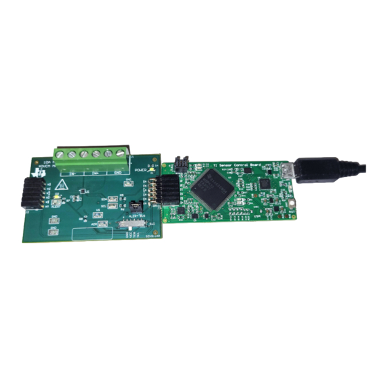
The GUI only supports one EVM/device type at a time and up to four EVMs total. Figure 3-2. Multiple EVMs Connected to SCB Controller SBOU285 – APRIL 2023 INA700EVM User’s Guide Submit Document Feedback Copyright © 2023 Texas Instruments Incorporated... - Page 6 With the MCU in DFU mode, upload the firmware through the method outlined in step 1. 3.2.1.3 GUI Setup and Connection The GUI can be accessed from this link in either Chrome, Firefox, or Safari: https://dev.ti.com/gallery/info/ CurrentSensing/INA700EVM_GUI/. INA700EVM User’s Guide SBOU285 – APRIL 2023 Submit Document Feedback Copyright © 2023 Texas Instruments Incorporated...
- Page 7 For first-time GUI Composer setup, follow the prompts to download the TI Cloud Agent and browser extension shown in Figure 3-5. Close the README.md dialog box to see these prompts. SBOU285 – APRIL 2023 INA700EVM User’s Guide Submit Document Feedback Copyright © 2023 Texas Instruments Incorporated...
- Page 8 Figure 3-8. Change Serial Port c. If the hardware still does not connect, make sure you are using the correct GUI and EVM combination. INA700EVM User’s Guide SBOU285 – APRIL 2023 Submit Document Feedback Copyright © 2023 Texas Instruments Incorporated...
- Page 9 (Registers) icon on the menu on the left. The Registers tab will look similar to the one shown in Figure 3-10. Figure 3-10. GUI Registers Tab SBOU285 – APRIL 2023 INA700EVM User’s Guide Submit Document Feedback Copyright © 2023 Texas Instruments Incorporated...
- Page 10 (Results Data) icon to open the Results Data page. Figure 3-12 shows part of the Results Data page for reference. Figure 3-12. Results Page and Settings INA700EVM User’s Guide SBOU285 – APRIL 2023 Submit Document Feedback Copyright © 2023 Texas Instruments Incorporated...
- Page 11 Change the number in this box to change the number of samples shown in each plot – Changing this number clears out the plot buffers, so the plots will be cleared on the next read SBOU285 – APRIL 2023 INA700EVM User’s Guide Submit Document Feedback Copyright © 2023 Texas Instruments Incorporated...
- Page 12 10 – Note when the SCB is reset while one or more EVMs are connected, the address will default to the lowest address found INA700EVM User’s Guide SBOU285 – APRIL 2023 Submit Document Feedback Copyright © 2023 Texas Instruments Incorporated...
- Page 13 – For this example, the EVM would return the results and state (idle or collecting) in JSON format: {"acknowledge":"wreg 0x01 0xfb69"} {"console":"Writing 0xfb69 to ADC_CONFIG register"} {"evm_state":"idle"} SBOU285 – APRIL 2023 INA700EVM User’s Guide Submit Document Feedback Copyright © 2023 Texas Instruments Incorporated...
- Page 14 Stop collecting data format: stop – Where stop is always lower case – The EVM will return the acknowledgment and state in JSON format: {"acknowledge":"stop"} {"evm_state":"idle"} INA700EVM User’s Guide SBOU285 – APRIL 2023 Submit Document Feedback Copyright © 2023 Texas Instruments Incorporated...
-
Page 15: Circuitry
ALERT pin from the EVM ALERT bus by disconnecting from J3. This is primarily used when working with multiple EVMs, so that the individual ALERT LEDs can be seen on each EVM when the ALERT bus is not needed. SBOU285 – APRIL 2023 INA700EVM User’s Guide Submit Document Feedback Copyright © 2023 Texas Instruments Incorporated... -
Page 16: Schematics, Pcb Layout, And Bill Of Materials
Board layouts are not to scale. These figures are intended to show how the board is laid out. The figures are not intended to be used for manufacturing EVM PCBs. 5.1 Schematics This section shows the schematics for the SENS104, also known as the INA700EVM. 5.1.1 SENS113 (INA700EVM) Figure 5-1 Figure 5-2 show the schematic of the EVM. - Page 17 These assemblies must be clean and free from flux and all contaminants. Use of no clean flux is not acceptable. Assembly Note These assemblies must comply with workmanship standards IPC-A-610 Class 2, unless otherwise specified. Figure 5-2. SENS113 Hardware Schematic SBOU285 – APRIL 2023 INA700EVM User’s Guide Submit Document Feedback Copyright © 2023 Texas Instruments Incorporated...
-
Page 18: Pcb Layout
PCB layers of the EVM. Figure 5-3. SENS113 Top View Figure 5-4. SENS113 Top Layer Figure 5-6. SENS113 Bottom Layer Figure 5-5. SENS113 Bottom View INA700EVM User’s Guide SBOU285 – APRIL 2023 Submit Document Feedback Copyright © 2023 Texas Instruments Incorporated... -
Page 19: Bill Of Materials
Test Point, Miniature, SMT Testpoint_Keystone_Miniatu 5015 Keystone TP5, TP7, TP8, TP10, TP11 40-V, 16-Bit, Precision PowerWCSP8 INA700AYWF Texas Instruments Digital Power/Energy/ Charge Monitor With Integrated Sense Element SBOU285 – APRIL 2023 INA700EVM User’s Guide Submit Document Feedback Copyright © 2023 Texas Instruments Incorporated... - Page 20 STANDARD TERMS FOR EVALUATION MODULES Delivery: TI delivers TI evaluation boards, kits, or modules, including any accompanying demonstration software, components, and/or documentation which may be provided together or separately (collectively, an “EVM” or “EVMs”) to the User (“User”) in accordance with the terms set forth herein.
- Page 21 www.ti.com Regulatory Notices: 3.1 United States 3.1.1 Notice applicable to EVMs not FCC-Approved: FCC NOTICE: This kit is designed to allow product developers to evaluate electronic components, circuitry, or software associated with the kit to determine whether to incorporate such items in a finished product and software developers to write software applications for use with the end product.
- Page 22 www.ti.com Concernant les EVMs avec antennes détachables Conformément à la réglementation d'Industrie Canada, le présent émetteur radio peut fonctionner avec une antenne d'un type et d'un gain maximal (ou inférieur) approuvé pour l'émetteur par Industrie Canada. Dans le but de réduire les risques de brouillage radioélectrique à...
- Page 23 www.ti.com EVM Use Restrictions and Warnings: 4.1 EVMS ARE NOT FOR USE IN FUNCTIONAL SAFETY AND/OR SAFETY CRITICAL EVALUATIONS, INCLUDING BUT NOT LIMITED TO EVALUATIONS OF LIFE SUPPORT APPLICATIONS. 4.2 User must read and apply the user guide and other available documentation provided by TI regarding the EVM prior to handling or using the EVM, including without limitation any warning or restriction notices.
- Page 24 Notwithstanding the foregoing, any judgment may be enforced in any United States or foreign court, and TI may seek injunctive relief in any United States or foreign court. Mailing Address: Texas Instruments, Post Office Box 655303, Dallas, Texas 75265 Copyright © 2023, Texas Instruments Incorporated...
- Page 25 TI products. TI’s provision of these resources does not expand or otherwise alter TI’s applicable warranties or warranty disclaimers for TI products. TI objects to and rejects any additional or different terms you may have proposed. IMPORTANT NOTICE Mailing Address: Texas Instruments, Post Office Box 655303, Dallas, Texas 75265 Copyright © 2023, Texas Instruments Incorporated...
Need help?
Do you have a question about the INA700EVM and is the answer not in the manual?
Questions and answers