Table of Contents
Advertisement
Quick Links
Instructions – Parts List
Parts
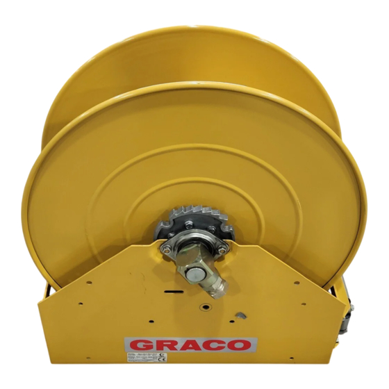
Series 750 Hose Reel
Model 245410, Series C
This reel is not to be used for overhead mount applications.
Low Pressure Fuel Dispense Reel: 375 psi (2.59 MPa, 25.9 bar) Maximum Working Pressure
Read warnings and instructions.
GRACO INC. P.O. BOX 1441 MINNEAPOLIS, MN 55440-1441
Copyright 2001, Graco Inc. is registered to I.S. EN ISO 9001
TI1619c
309442 rev.E
Advertisement
Table of Contents

Related Manuals for Graco 750 Series


Summary of Contents for Graco 750 Series
- Page 1 This reel is not to be used for overhead mount applications. Low Pressure Fuel Dispense Reel: 375 psi (2.59 MPa, 25.9 bar) Maximum Working Pressure Read warnings and instructions. TI1619c GRACO INC. P.O. BOX 1441 MINNEAPOLIS, MN 55440-1441 Copyright 2001, Graco Inc. is registered to I.S. EN ISO 9001...
-
Page 2: Table Of Contents
..... . . Graco Standard Warranty .... -
Page 3: Warnings
D Read all instruction manuals, tags, and labels before operating the equipment. D Use the equipment only for its intended purpose. If you are not sure, call your Graco distributor. D Do not alter or modify this equipment. Use only genuine Graco parts and accessories. Modifying parts can cause a malfunction and result in serious bodily injury. - Page 4 WARNING TOXIC FLUID HAZARD Hazardous fluid or toxic fumes can cause serious injury or death if inhaled, swallowed, splashed in the eyes, or splashed on the skin. D Know the specific hazards of the fluid you are using. D Store hazardous fluid in an approved container. Dispose of hazardous fluid according to all local, state and national guidelines.
-
Page 5: Typical Layout
Contact your Graco distributor vent possible misalignment and binding. for assistance in designing a system to suit your needs. -
Page 6: Installing A Hose
Installation–Hose To install a hose on a hose reel with the proper amount WARNING of spring tension, follow these steps: WARNING Never allow the reel to spin freely. Doing so causes the hose to spin out of control, which could cause serious injury if you are hit by the hose. -
Page 7: Adjusting Spring Tension
Installation–Adjusting Spring Tension If the hose cannot be pulled out all the way, or if it does 4. Rotate the reel in the direction of the appropriate not retract all the way back onto the hose reel, you arrow shown in Fig. 3, keeping the hose wrapped need to adjust the spring tension. -
Page 8: Maintenance
Maintenance Pressure Relief Procedure Replacing the Service Hose WARNING WARNING The system pressure must be manually relieved to prevent the system from dispensing accidentally. To reduce the risk of serious injury whenever you To reduce the risk of an injury from injection, are instructed to relieve pressure, always follow splashing fluid, or moving parts, follow the Pres- the Pressure Relief Procedure at left. -
Page 9: Oiling The Hose Rollers
Maintenance Oiling the Hose Rollers WARNING Every six months, apply one or two drops of light Never allow the reel to spin freely. Doing so motor oil to lubricate the hose reel at point A. See causes the hose to spin out of control, which could Fig. -
Page 10: Service
Service Swivel and Bearings WARNING To reduce the risk of serious injury whenever you are instructed to relieve pressure, always follow the Pressure Relief Procedure at left. 1. Relieve the pressure. 2. Remove the 90_ inlet adapter (24) (see Fig. 6). 3. -
Page 11: Spring Canister
Service Spring Canister To replace the spring canister, follow the steps below. Do not attempt to service the spring inside of the spring canister. Read the warning below regarding the spring hazard. WARNING HOSE REEL SPRING HAZARD The only service you should perform on the reel spring is replacing the spring canister. -
Page 12: Parts Drawing
Parts Drawing {18a {18b {18d {18e {18c }22d 13,28 }22a }22c }22b }22f 22g} 15,19 22e} 12,26 TI1620C 309442E... -
Page 13: Parts List
Parts List Part No. Description Part No. Description NUT, hex; 1/4–20 SCREW; 3/8–16 x 5/8 in. SPACER, ratchet 117132 END FRAME 117149 KIT, latch pawl 119443 KIT, bearing Includes items 22a–22g Includes items 3a–3d 22a} SCREW; 10–32 x 7/8 in. PILLOW BLOCK ASSY. -
Page 14: Technical Data
Technical Data Maximum working pressure ........... 375 psi (2.59 MPa, 25.9 bar) Inlet size . -
Page 15: Dimensions
Dimensions 1!/2 npt(f) outlet npt(f) inlet ti1619d 26.25 in. (667 mm) overall height 26.25 in. (667 mm) overall length 21.88 in. (556 mm) overall width 13.75 in. (349 mm) base to port center 24.25 in. (616 mm) base length 17.50 in. (445 mm) base width G 22.125 in. -
Page 16: Graco Standard Warranty
With the exception of any special, extended, or limited warranty published by Graco, Graco will, for a period of twelve months from the date of sale, repair or replace any part of the equipment determined by Graco to be defective.
Need help?
Do you have a question about the 750 Series and is the answer not in the manual?
Questions and answers