Table of Contents
Advertisement
Quick Links
Installation
™
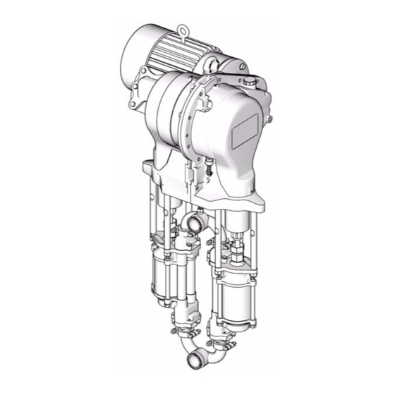
E-Flo
Circulation Pump
Durable, energy efficient piston pumps for high volume paint circulation
applications.
See page 3 for model information, including maximum working pressure and approvals.
Important Safety Instructions
Read all warnings and instructions in this manual.
Save these instructions.
Graco Inc. P.O. Box 1441 Minneapolis, MN 55440-1441
Copyright 2007, Graco Inc. is registered to I.S. EN ISO 9001
Plus Electric
311592 rev. B
ti8317a
Advertisement
Table of Contents

Related Manuals for Graco E-Flo Plus


Summary of Contents for Graco E-Flo Plus
- Page 1 See page 3 for model information, including maximum working pressure and approvals. Important Safety Instructions Read all warnings and instructions in this manual. Save these instructions. ti8317a Graco Inc. P.O. Box 1441 Minneapolis, MN 55440-1441 Copyright 2007, Graco Inc. is registered to I.S. EN ISO 9001...
-
Page 2: Table Of Contents
Increased Safety (European) ....10 Graco Information ......20 288036 Power Module . -
Page 3: Models
2000 cc Pumps: 250 psi (1.75 MPa, 17.5 bar) Maximum Working Pressure See Technical Data, page 21, for pump operational limits. Approvals Related Manuals The E-Flo Plus Pump meets requirements of the follow- Manual Description ing approval agencies. 311593 E-Flo Plus Operation Manual... -
Page 4: Warnings
Warnings Warnings The following warnings are for the setup, use, grounding, maintenance, and repair of this equipment. The exclama- tion point symbol alerts you to a general warning and the hazard symbol refers to procedure-specific risk. Refer back to these warnings. Additional, product-specific warnings may be found throughout the body of this manual where applicable. - Page 5 Warnings WARNING PRESSURIZED EQUIPMENT HAZARD Fluid from the gun/dispense valve, leaks, or ruptured components can splash in the eyes or on skin and cause serious injury. • Follow Pressure Relief Procedure in this manual, when you stop spraying and before cleaning, checking, or servicing equipment.
-
Page 6: System Components
3-Way Pneumatic Solenoid Valve (accessory) See F . 1. The following system components are approved for use in a hazardous area: • E-Flo Plus Electric Circulation Pump • Sensor Control Circuit (option). See intrinsic safety installation requirements below. Sensor Circuit Wetted Parts Pressure transducer: 17-4 PH stainless steel •... - Page 7 Hazardous Area ti8651a . 1: Typical Installation Key: Pump Stand R** Fluid Inlet Line E-Flo Plus Electric Circulation Pump S** Fluid Outlet Line Explosion-Proof Electric Motor T** Fluid Return Line Local Control Box Pneumatic Back Pressure Regulator Variable Frequency Drive (VFD)
-
Page 8: System Wiring Schematics
System Wiring Schematics System Wiring Schematics . 2 shows components that must be installed in a . 3 shows components approved for installation in a non-hazardous location. hazardous location. . 2: System Wiring Schematic, Non-Hazardous Location Only 311592B... - Page 9 System Wiring Schematics SEE DETAIL BELOW SEE ABOVE . 3: System Wiring Schematic, Hazardous Location 311592B...
-
Page 10: Power Supply Requirements
Power Supply Requirements Power Supply Requirements Hazardous Area Cabling and Conduit Requirements (Explosion Proof) Improper wiring may cause electric shock or other serious injury if work is not performed properly. Have a qualified electrician perform any electrical work. Be sure your installation complies with all National, State and Local safety and fire codes. -
Page 11: Pump Location
Pump Location Pump Location Connect Fluid Lines See F . 4. The fluid manifolds are secured to the Environmental Conditions pumps with 1-1/2 in. clamps and sanitary gaskets (CG). Manifolds can be oriented in either direction. Connect See Technical Data, page 19, for recommended ambi- the fluid line (R) to the manifold (MF) using 2 in. -
Page 12: Electric Motor
IEC 112M/B5 Frame. 311605. • To install a IEC 112M/B5 Frame electric motor, Graco does not support the use of the Graco VFD order Motor Adapter Kit 15J893. See manual CAM mode on motors not supplied by Graco. 311605. - Page 13 Electric Motor Apply antiseize lubricant to bore of coupling (28). ti8726a Motor Rotation (counter-clockwise as viewed from fan end) . 6. NEMA 184 TC Frame Electric Motors ti8913a . 5. Install the Coupler When installing an IEC 112M/B5 Frame electric motor, ensure that the motor adapter (60) and screws (59) are in place before mounting the motor on the gear reducer.
-
Page 14: Electrical Noise Filter
. 2 Electrical Schematic on page 8. Install the electrical noise filter in the non-haz- 2.91 in. ardous area, upstream of the VFD. 73.9 mm Graco supplies accessory noise filters, depending on your system voltage. See T ABLE Table 5: Electrical Noise Filters Rated Mounting Hole Part No. -
Page 15: Variable Frequency Drive Accessory (Vfd)
Variable Frequency Drive Accessory (VFD) Variable Frequency Drive Accessory (VFD) Use a variable frequency drive (VFD) accessory to pro- vide motor drive control to the pump. Graco supplies accessory VFDs that optimize pump performance. Order Part No. 15J753 (200-240 Vac) or 15J754 (380-480 Vac), depending on your system voltage. -
Page 16: 120373 Local Control Box (Optional Accessory)
120373 Local Control Box (optional accessory) 120373 Local Control Box (optional accessory) See F . 1 on page 7, and F . 11. Install the local con- Local Control Box has 1 in. npt conduit connection point trol box (C) in the hazardous area as close to pump as on top and bottom for installation convenience. -
Page 17: Pneumatic Back Pressure Regulator (Optional)
Pneumatic Back Pressure Regulator (optional) Pneumatic Back Pressure Regulator (optional) See F . 1 on page 7, and F . 12. Install the back pres- sure regulator (U) in the fluid return line in the hazard- ous area. Three sizes of fluid inlets and outlets (FI, FO) are available. -
Page 18: Dimensions
Dimensions Dimensions E-Flo Plus Electric Circulation Pump 21.6 in. 29.6 in. (752 mm) (549 mm) 48.1 in. (1222 mm) 2 in. Sanitary (f) Fluid Outlet 22.4 in. (569 mm) 2 in. Sanitary (f) Fluid Inlet ti8916a ti8917a 1.625 in. (41.3 mm) -
Page 19: Technical Data
Gear Reducer Oil Capacity ..... . . 2 quarts (1.9 liters) Required Gear Reducer Lubricant ....ISO VG220 grade oil (Graco Part No. 288414) Weight (with motor and 2000 cc lowers) . -
Page 20: Graco Standard Warranty
With the exception of any special, extended, or limited warranty published by Graco, Graco will, for a period of twelve months from the date of sale, repair or replace any part of the equipment determined by Graco to be defective.
Need help?
Do you have a question about the E-Flo Plus and is the answer not in the manual?
Questions and answers