
Related Manuals for Rockwell Automation E3


Summary of Contents for Rockwell Automation E3
- Page 1 E3 and E3 Plus Solid-State Overload Relay Quick Start Guide (Bulletins 193 and 592)
-
Page 2: Important User Information
The illustrations, charts, sample programs and layout examples shown in this guide are intended solely for purposes of example. Since there are many variables and requirements associated with any particular installation, Rockwell Automation does not assume responsibility or liability (to include intellectual property liability) for actual use based upon the examples shown in this publication. -
Page 3: General Precautions
Failure to comply may result in personal injury/equipment damage. An incorrectly applied or installed E3 Overload Relay can result in IMPORTANT damage to the components or reduction in product life. Wiring or... - Page 4 Introduction Follow these steps to successfully commission the E3 Overload Relay: Table 1: Commissioning Procedure Step Description Hardware Installation Wiring Installation – Typical Motor Connections – External Current Transformer Applications (193-EC_ZZ or 592-EC_ZZ) – External Ground Fault Sensor Applications (193-EC3_ _ , 592-EC3_ _ and...
-
Page 5: Hardware Installation
Hardware Installation The following figures illustrate the starter assembly instructions. Starter Assembly Instructions Figure 1: 100-C09…C43 Starter Assembly Instructions (for use with Cat. Nos. 193-EC_ _B and -EC_ _D) 22 lb-in. CLICK Publication 193-QR003B-EN-P - October 2009... - Page 6 Figure 2: 100-C60…C85 Starter Assembly Instructions (for use with Cat. No. 193-EC_ _E). 35 lb-in. Publication 193-QR003B-EN-P - October 2009...
- Page 7 Figure 3: 100-D95...D860 Starter Assembly Instructions (for use with Cat. Nos. 193-EC_ _F, 193-EC_ _G, and 193-EC_ _H). Publication 193-QR003B-EN-P - October 2009...
-
Page 8: Wiring Installation
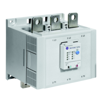
• Lug kit catalog numbers (108…1250 A) For reliable input signal processing, input wiring should be routed in raceways separate from power cabling. Terminal Designations Figure 4: E3 and E3 Plus Feature Overview LED Status Indicators E3 PLUS Test/Reset Button... -
Page 9: Control Terminals
— External ground fault sensor input Features are available only with the E3 Plus Overload Relay (cat. nos. 193/592-EC2and 193/592-EC3). Available only on cat. nos. 193/592-EC5_ _. An earth ground connection to this terminal will assist in obtaining compliance with electromagnetic compatibility requirements. -
Page 10: Wiring Diagrams
The following grounding recommendations are provided to ensure electromagnetic compatibility compliance during installation: • The earth ground terminal of the E3 Overload Relay shall be connected to a solid earth ground via a low-impedance connection • Installations employing an external ground fault sensor shall ground the cable shield at the sensor with no connection made at the E3 Plus Overload Relay •... - Page 11 External Current Transformer Application (Cat. No. 193-EC_ZZ) E3 and E3 Plus Overload Relays (Cat. No. 193-EC_ZZ) are designed for use with separately mounted, customer-supplied current transformers (CTs) as required in higher-current applications. The FLA setting range is 9…5000 A for these units, with a legal setting range per the user’s manual.
-
Page 12: Installation Instructions
The E3 Overload Relay must be mounted a distance equal to, or greater than, six times the cable diameter (including insulation) from the nearest current-carrying conductor or current transformer. - Page 13 Parameter 289, PT Pri, and the secondary winding rating into Parameter 290, PT Sec. The voltage mode is also programmed into the E3 Plus by selecting the appropriate mode in Parameter 156, Volt Mode. The E3 Plus will support Wye, Delta, and Open Delta voltage modes with potential transformers.
- Page 14 Figure 8: External PT Connection Diagrams Line N/GND Wye Connection with PTs Load Line Delta Connection with PTs Load Line Open Delta Connection with PTs Load Publication 193-QR003B-EN-P - October 2009...
- Page 15 (including insulation) from the sensor. 4. The power cables of the branch circuit to be protected by the E3 Plus Overload Relay must not be grounded on the load side of the ground fault sensor.
- Page 16 Figure 11: Power Cable Configuration — Two Cables per Phase The spacer is a short (approximately 10 times the cable diameter in length) piece of cable with no connections to any terminal. Figure 12: Ground Fault Sensor Wiring to the E3 Plus Overload Relay 193-CBCT_ Ground Fault...
- Page 17 63 should be left vacant for introduction of new slave devices. The node address and data rate for series B or later, E3 Overload Relays can be changed using software or by setting the hardware switches that reside on the front of each unit. While both methods yield the same result, it is good practice to choose one method and deploy it throughout the system.
-
Page 18: Setup Requirements
For switch settings in this range, the node address setting is determined by the software setting using the RSNetWorx for DeviceNet configuration tool. Factory default setting. Note: For node address switch values in the range of 0…63, cycle power to the E3 Overload Relay to initialize the new setting. Setup Requirements Setup for Cat. - Page 19 Protective Trip/Warning Summaries & Parameter Group Listing (Cat. Nos. 193/592-EC1/EC2/EC3/EC5) Table 3: Trip Summary Trip Trip Trip Level Settings Trip Delay Settings Inhibit Time Function Enable Settings Factory Range Default Range Default Range Default Default Overload Enabled Trip Class Trip Class —...
- Page 20 Table 3: Trip Summary Trip Trip Trip Level Settings Trip Delay Settings Inhibit Time Function Enable Settings Factory Range Default Range Default Range Default Default Under Disabled 0…32767 0.1…25.0 s 1.0 s 0…250 s 10 s Consumed kVAR Over Consumed Disabled 0…32767 0.1…25.0 s...
- Page 21 Table 4: Warning Summary Warning Warning Warning Level Settings Inhibit Time Settings Function Enable Range Default Range Default Factory Default Overload Disabled 0…100% — — Phase Loss — — — — — Ground Fault (193/592-EC2) Disabled Internal 1…5 2.0 A 0…250 s 10 s Ground Fault (193/592-EC3)
- Page 22 Table 5: Parameter Group Listing Monitor Overload DeviceNet Output Params Setup Reset/Lock Advanced Setup Setup Setup DeviceLogix 27 Single/ 1 L1 Current Three Ph 26 Trip Reset 24 Trip Enable 55 AutoBaudEnable 65 OutA Pr FltState 79 Comm Override 66 OutA Pr 80 Network 2 L2 Current 28 FLA Setting...
- Page 23 Table 6: Parameter Group Listing, Continued TripWarn Trip Snapshot Voltage Power Monitor Device History Monitor Voltage Setup Power Setup Logix 79 Comm Override 132 Trip History 0 144 SS L1 Current 160 V Trip Status 156 Volt Mode 173 L1 Real Power 157 Power Scale 80 Network Override...
- Page 24 Setup for Cat. No. 193-EC4 Current Monitor Relay After the E3 Plus Current Monitor Relay is installed according to the guidelines specified in this manual, apply power to the relay’s DeviceNet connector. After applying power, the following sequence should occur: 1.
- Page 25 Protective Trip/Warning Summaries & Parameter Group Listing (Cat. No. 193-EC4) Table 7: Trip Summary Trip Trip Enable Trip Level Settings Trip Delay Settings Inhibit Time Function Factory Settings Default Range Default Range Default Range Default Ground Fault Disabled 0.02…5 A 2.5 A 0.0…25 s 0.5 s...
- Page 26 Table 8: Warning Summary Warning Warning Warning Level Warning Delay Settings Inhibit Time Function Enable Settings Settings Factory Range Default Range Default Range Default Default Ground Fault Disabled 0.02…5 A 2.0 A 0.0…25 s 0.0 s 0…250 s 10 s Disabled 0.2…45 A —...
- Page 27 Table 9: Parameter Group Listing (Cat. No. 193-EC4) Monitor Reset / Lock Advanced Setupt DeviceNet Setup Output Setup DeviceLogix Params 1 L1 Current 26 Trip Reset 24 Trip Enable 55 AutoBaudEnable 65 OutA Pr FltState 79 Comm Override 2 L2 Current 53 Program Lock 25 Warning Enable 56 NonVol Baud Rate...
-
Page 28: Short-Circuit Ratings
National Electrical Code and any othergoverning regional and local codes The Bulletin 193/592 E3 Overload relay is suitable for use on circuits capable of delivering not more than the RMS symmetrical amperes listed in the followign tables: Publication 193-QR003B-EN-P - October 2009... - Page 29 Table 11: Standard Fault Short-Circuit Ratings per UL 508 and CSA 22.2, No. 14 Cat. No. Max. Available Fault Max. Voltage [V] Current [A] 193-EC_B, 592EC_T 5000 193-EC_D, 592EC_C 5000 193-EC_E, 592EC_D 10000 193-EC_F 10000 193-EC_G 18000 193-EC_H 42000 193-EC_Z 5000 Publication 193-QR003B-EN-P - October 2009...
- Page 30 Table 12: High Fault Short-Circuit Ratings per UL 508 and CSA 22.2, No. 14 with Bulletin 100-C and 100-D contactors Cat. No. Contactor Max. Max. Available Max. Max. Class J or CC Starter Fault Current Voltage Fuse [A] FLC [A] 100-C09 100-C12 100-C16...
- Page 31 Table 13: High Fault Short-Circuit Ratings per UL 508 and CSA 22.2, No. 14 with NEMA contactors Cat. No. Contactor Max. Available Max. Max. UL Fuse [A] Circuit Breaker/ Size Fault Current Voltage Limiter 100000 — — FDB 3025/ LFB3070R 100000 FDB 3025/ LFB3070R...
-
Page 32: Fuse Coordination
Fuse Coordination Table 15: IEC Type 1 and Type II Fuse Coordination with Bulletin 100-C and 100-D Contactors per EN60947-4-1 Cat. No. Contactor Max. Prospective Conditional Max. Type I Type II Starter Short-Circuit Short-Circuit Voltage with Class with FLC [A] Current I Current I J Fuse [A]... - Page 33 Table 16: Type 1 and Type II Fuse Coordination with NEMA Contactors Cat. No. Contactor Max. Prospective Conditional Max. Type I with Type II Size Starter Short-Circuit Short-Circuit Voltage Class J with Class FLC [A] Current I Current I Fuse [A] J Fuse [A] 592-EC_T 1000...
- Page 34 Publication 193-QR003B-EN-P - October 2009 PN-37176 Supercedes publication 193-QR003A-EN-P - January 2008 Copyright ©2009 Rockwell Automation, Inc. All Rights Reserved. Printed in USA...
Need help?
Do you have a question about the E3 and is the answer not in the manual?
Questions and answers