Sign In
Upload
Manuals
Brands
Rockwell Automation Manuals
Relays
Allen-Bradley E3
Rockwell Automation Allen-Bradley E3 Manuals
Manuals and User Guides for Rockwell Automation Allen-Bradley E3. We have
3
Rockwell Automation Allen-Bradley E3 manuals available for free PDF download: User Manual, Quick Start Manual
Rockwell Automation Allen-Bradley E3 User Manual (192 pages)
Overload Relays
Brand:
Rockwell Automation
| Category:
Relays
| Size: 2 MB
Table of Contents
Conventions
5
Preface
5
Vocabulary
5
Who Should Use this Manual
5
Reference Manuals
6
Table of Contents
7
Chapter 1 - Product Overview
17
Introduction
17
Description
17
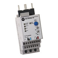
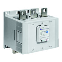
Figure 1.1 E3 and E3 Plus Overload Relays
17
Catalog Number Explanation
18
Single-/Three-Phase Operation
18
Protection and Warning Functions
18
Figure 1.2
18
Current Monitoring Parameters
19
Diagnostic Parameters
19
Trip Relay
19
Inputs and Outputs
20
Table 1.A E3 Overload Relay Inputs and Outputs
20
Status Indication
21
Test/Reset Button
22
Devicenet Compatibility
22
Chapter 2 - Installation and Wiring
23
Introduction
23
Receiving
23
Unpacking/Inspecting
23
Storing
23
General Precautions
24
Starter Installation
26
Starter Assembly Instructions
26
Figure 2.1 100-C09
26
Figure 2.2 100-C60
27
Starter Approximate Dimensions
28
Figure 2.3 Bulletin 109 Approximate Starter Dimensions
28
Table 2.A Bulletin 109 Approximate Starter Dimensions
28
Figure 2.4 Bulletin 509 Approximate Starter Dimensions
29
Table 2.B Bulletin 509 Approximate Starter Dimensions
30
Panel Mount Adapter Installation
31
Panel Mount Adapter Assembly Instructions
31
Figure 2.5 193-ECPM1 and 193-ECPM2 Panel Mount Adapter
31
Figure 2.6 193-ECPM3 Panel Mount Adapter Assembly Instructions
32
Panel Mount Adapter Approximate Dimensions
33
Figure 2.7 193-ECPM1 Panel Mount Adapter Approximate Dimensions
33
Figure 2.8 193-ECPM2 Panel Mount Adapter Approximate Dimensions
34
Figure 2.9 193-ECPM3 Panel Mount Adapter Approximate Dimensions
34
Wire Size and Torque Specifications
35
Power Terminals
35
Control and Devicenet Terminals
35
Table 2.C Power Terminal Wire Size and Torque Spec
35
Table 2.D Control and Devicenet Terminal Wire Size and
35
Terminal Designations
36
Control Terminals
36
Devicenet Terminals
36
Table 2.E Control Terminal Designation
36
Table 2.F Devicenet Terminal Designation
36
Short-Circuit Ratings
37
Table 2.GUL Short-Circuit Ratings
37
Table 2.HIEC Short-Circuit Ratings
37
Fuse Coordination
38
Table 2.I Type I and Type II Fuse Coordination with 100-C Contactors
38
Table 2.J Type I and Type II Fuse Coordination with NEMA Contactors
38
Typical Motor Connections
39
Three-Phase Full-Voltage
39
Figure 2.10 Three-Phase Full-Voltage Wiring Diagram
39
Single-Phase Full-Voltage
40
Figure 2.11 Single-Phase Full-Voltage Wiring Diagram
40
Typical Control Circuit Wiring Diagrams
41
Full-Voltage Non-Reversing (with Network Control)
42
Figure 2.12 Full-Voltage Non-Reversing Starter Wiring Diagram (NEMA Nomenclature)
42
Full Voltage Reversing (with Network Control)
43
Figure 2.14 Full-Voltage Reversing Starter Wiring Diagram (NEMA Nomenclature)
43
Figure
43
Full-Voltage Reversing Starter Wiring Diagram (CENELEC Nomenclature)
43
Two-Speed Non-Reversing (with Network Control)
44
Two-Speed Non-Reversing Starter Wiring Diagram (NEMA Nomenclature)
44
Figure
44
Two-Speed Non-Reversing Starter Wiring Diagram (CENELEC Nomenclature)
44
Chapter 3 - Protective Trip and Warning Functions
45
Introduction
45
Trip Enable
45
Warning Enable
45
Overload Protection
46
Overload Trip
46
FLA Setting
46
Trip Class
47
Trip Curves
47
Time-Current Characteristics for Trip Classes
48
Table 3.A Time-Current Characteristic Scaling Factors
49
Auto/Manual Reset
50
Table 3.B Typical Overload Relay Reset Time Delays
50
Overload Reset Times
51
Overload Warning
52
Overload Diagnostics
52
Non-Volatile Thermal Memory
53
Phase Loss Protection
53
Phase Loss Trip
53
Ground Fault Protection (E3 Plus)
55
Ground Fault Trip
55
Table 3.C Recommended Phase Loss Trip Delay Settings for Explosive Environment Applications
55
Ground Fault Warning
57
Stall Protection
57
Stall Trip
57
Jam Protection
59
Jam Trip
59
Jam Warning
60
Underload Protection
60
Underload Trip
61
Underload Warning
62
Thermistor/Ptc Protection (E3 Plus)
62
Table 3.D E3 Plus PTC Input Ratings
63
PTC Trip
64
PTC Warning
64
Current Imbalance Protection
65
Current Imbalance Trip
65
Current Imbalance Warning
66
Communication Fault Protection
67
Comm Fault Trip
67
Comm Fault Warning
68
Communication Idle Protection
68
Comm Idle Trip
68
Comm Idle Warning
69
Protective Trip and Warning Summary
70
Chapter 4 - Devicenet Node Commissioning
72
Introduction
72
Example Network
72
Devicenet Network Diagram
72
Single Pass Browse
73
Building and Registering an EDS File
74
Changing the Node Address (MAC ID)
82
Device Parameter Programming - Input and Output Assemblies
85
Output Assemblies
85
Mapping to the Scanner's Scanlist
92
Input/Output Mapping in the Scanlist
97
Chapter 5 - Programmable Parameters
99
Introduction
99
Parameter Programming
99
Program Lock
99
Resetting to the Factory Default Values
99
Parameter Group Listing
100
Overload Setup Group
101
Advanced Setup Group
104
Reset/Lock Group
111
Devicenet Setup Group
112
Output Setup Group
115
Chapter 6 - Current Monitoring Parameters
119
Introduction
119
Phase Current Reporting
119
Current Range
119
Frequency Range
120
Reporting Accuracy
121
Ground Fault Current Reporting
121
Current Range
121
Frequency Range
121
Monitor Group
122
Chapter 7 - Diagnostic Parameters
125
Introduction
125
Monitor Group
125
Chapter 8 - Logic Controller Application Example with Explicit Messaging
130
Introduction
130
I/O Mapping
130
Examples
133
Sequence of Events
133
Setting up the Data File
133
Get_Attribute_Single Structure
134
Figure
135
Chapter 9 - Troubleshooting
136
Introduction
136
Advisory Leds
137
Trip/Warn LED
137
Network Status LED
138
OUT a & out B Leds
138
In 1,2,3 & 4 Leds
138
Power-Up Sequence
139
Devicenet Modes of Operation
140
Power-Up Reset Mode
140
Run Mode
140
Recoverable Error Mode
141
Unrecoverable Error Mode
141
Resetting a Trip
142
Trip/Warn LED Troubleshooting Procedures
143
Devicenet Troubleshooting Procedures
145
Input and Output Troubleshooting Procedures
146
Appendix A - Specifications
148
Electrical Specifications
148
E3 & E3 Plus Power Supply Current
149
Environmental Specifications
151
Electromagnetic Compatibility Specifications
151
Functionality Specifications
152
Protection
153
Electronic Data Sheets
154
Product Codes
154
Devicenet Objects
155
Identity Object - Class Code 0X01
156
Message Router - Class Code 0X02
157
Devicenet Object - Class Code 0X03
157
Assembly Object - Class Code 0X04
159
Output Assemblies
159
Input Assemblies
160
Connection Object - Class Code 0X05
162
Discrete Input Point Object - Class Code 0X08
165
Discrete Output Point Object - Class Code 0X09
166
Parameter Object - Class Code 0X0F
167
Parameter Group Object - Class Code 0X10
168
Control Supervisor Object - Class Code 0X29
173
Acknowledge Handler Object - 0X2B
176
Overload Object - Class Code 0X2C
176
Devicenet Interface Object - Class Code 0Xb4
180
PCP Object - Class Code 0Xc2
181
ODVA Fault Codes
182
Appendix C - Explosive Environment Applications
184
Introduction
184
Protection Requirements
184
Overload Protection
184
PTC Protection (E3 Plus
185
Phase Loss Protection
185
Power Supply Requirements
186
Devicenet - Networked
186
Stand-Alone
186
Control Wiring Requirements
187
OUT a or out B
187
Full Voltage Non-Reversing Starter Wiring Diagram (with Network Control
188
Advertisement
Rockwell Automation Allen-Bradley E3 Quick Start Manual (35 pages)
Solid-State Overload Relay
Brand:
Rockwell Automation
| Category:
Relays
| Size: 2 MB
Table of Contents
Important User Information
2
General Precautions
3
Hardware Installation
5
Wiring Installation
8
Control Terminals
9
Wiring Diagrams
10
Installation Instructions
12
Setup Requirements
18
Short-Circuit Ratings
28
Fuse Coordination
32
Rockwell Automation Allen-Bradley E3 User Manual (44 pages)
Progamming and Control Terminal
Brand:
Rockwell Automation
| Category:
Touch terminals
| Size: 1 MB
Advertisement
Advertisement
Related Products
Rockwell Automation Allen-Bradley E300
Rockwell Automation Allen-Bradley E3 Plus
Rockwell Automation Allen-Bradley GuardMaster MSR55P Back EMF Minotaur
Rockwell Automation Allen-Bradley Guardmaster GLP
Rockwell Automation Allen-Bradley Guardmaster DI
Rockwell Automation Allen-Bradley Guardmaster DIS
Rockwell Automation Allen-Bradley Guardmaster EM
Rockwell Automation Allen-Bradley Guardmaster EMD
Rockwell Automation Allen-Bradley Guardmaster SI
Rockwell Automation Allen-Bradley GLT
Rockwell Automation Categories
Controller
Control Unit
Power Supply
DC Drives
Industrial Equipment
More Rockwell Automation Manuals
Login
Sign In
OR
Sign in with Facebook
Sign in with Google
Upload manual
Upload from disk
Upload from URL