Grundfos UNILIFT APG Installation And Operating Instructions Manual
Hide thumbs
Also See for UNILIFT APG:
- Safety instructions and other important information (38 pages) ,
- Service instructions manual (15 pages) ,
- Installation and operating instructions manual (238 pages)
Table of Contents
Advertisement
Quick Links
Advertisement
Table of Contents

Related Manuals for Grundfos UNILIFT APG


Summary of Contents for Grundfos UNILIFT APG
- Page 1 GRUNDFOS INSTRUCTIONS UNILIFT APG Installation and operating instructions...
- Page 3 UNILIFT APG English (GB) Installation and operating instructions ........5 Български...
- Page 4 Appendix A ..........532 UNILIFT APG...
-
Page 5: Table Of Contents
Installation on auto coupling ..10 The symbols and hazard statements below may Free-standing installation ... 11 appear in Grundfos installation and operating Adjustment of the float switch cable instructions, safety instructions and service length . -
Page 6: Notes
1.2 Notes 2. Product introduction The symbols and notes below may appear in Grundfos installation and operating instructions, safety instructions and service instructions. A blue or grey circle with a white graphical symbol indicates that an action must be taken. -
Page 7: Product Description
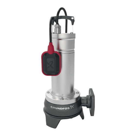
2.1 Product description 2.4 Identification The Grundfos UNILIFT APG pump is designed for 2.4.1 Nameplate, UNILIFT APG pumping wastewater. The compact design makes the pump suitable for both temporary and permanent installation. The pump can be installed on an auto- coupłing system or stand freely on the bottom of the... -
Page 8: Receiving The Product
4. Installation requirements 2.4.2 Type key, UNILIFT APG Example: UNILIFT APG.40.10.A1. 1x220-240V SCH CAUTION Toxic material Code Explanation Designation Minor or moderate personal injury ‐ The product will be classified as conta- UNILIFT Product name minated if it has been used for a liquid which is injurious to health or toxic. -
Page 9: Mechanical Installation
5. Mechanical installation CAUTION · · · · · · · · · · · · · · Sharp element · · · · · · · · · · · · · · · · · · · · ·... -
Page 10: Installation On Auto Coupling
5.4 Installation on auto coupling 7. Fit the guide claw to the pump outlet. Grease the gasket of the guide claw before lowering the pump See the appendix for drawing of auto-coupling into the pit. dimensions. 8. Mount the lifting shackle and the lifting chain to Pumps for permanent installation can be mounted on the handle of the pump on the opposite side of the a stationary auto-coupling guide-rail system or a... -
Page 11: Free-Standing Installation
5.5 Free-standing installation Pos. Description See the appendix for dimensional drawing. Stop For free-standing installation of the pumps, fit a 90° Start elbow to the outlet. The pump can be installed with a rigid pipe and valves. Cable length (L) In order to facilitate service of the pump, fit a flexible connection or coupling to the outlet pipe for easy The start and stop levels vary according to the cable... -
Page 12: Electrical Connection
6. Electrical connection If a float switch is connected to a three-phase pump, the motor-protective circuit breaker must be DANGER magnetically operated. Electric shock Single-phase pumps incorporate thermal overload Death or serious personal injury protection and require no additional motor protection. ‐... -
Page 13: Checking The Direction Of Rotation
6.1 Checking the direction of rotation Pos. Description Three-phase pumps only Float switch CAUTION Motor Sharp element Minor or moderate personal injury ‐ Do not touch the sharp edges of the impeller, grinder head and grinder ring without wearing protective gloves. The impeller rotates counterclockwise. -
Page 14: Starting Up The Product
If the power cable or the float switch is merged in the pumped liquid. damaged, it must be replaced by a service workshop authorised by Grundfos. 1. Before starting the pump, submerge the pump inlet in the pumped liquid. Service must be carried out by specially 2. -
Page 15: Maintaining The Product
• If the drained oil contains water or other Pos. Description impurities, we recommend that you replace the Spline shaft seal. Contact Grundfos Service. Set screw 8.2 Oil Screw In the case of long operating time or continuous Plate operation, the oil must be replaced as follows:... -
Page 16: Service Kits
8.4 Service kits The following service kits are available for all pumps. O-ring mate- Product num- Service kit Contents Pos. rial 49, 9a, 66, Impeller 92693611 188a 45, 44, 44a, Grinder parts 92693612 66, 188a Set of screws 5 × M8, 3 × M6 26, 12c 92693631 O-ring kit... -
Page 17: Maintenance Schedule
8.5 Maintenance schedule 8.7 Replacing the grinder system Inspect pumps running normal operation every 3000 CAUTION operating hours or at least once a year. If the dry- Sharp element solids content of the pumped liquid is very high or Minor or moderate personal injury sandy, check the pump at shorter intervals. -
Page 18: Changing The Oil
(66) in the shaft end. necessary at a Grundfos Service Center. In this case also change the oil with about 140 ml of oil, 3. Remove the grinder head (45). -
Page 19: Contaminated Pumps
The product will be classified as contaminated if it has been used for a liquid which is injurious to health or toxic. If you request Grundfos to service the product, contact Grundfos with details about the pumped liquid before returning the product for service. Otherwise, Grundfos can refuse to accept the product for service. -
Page 20: Fault Finding
9.2 The motor protection or thermal relay trips after a short time of operation Cause Remedy The liquid temperature is too high. Use another pump type. Contact your local Grundfos supplier or sales support. The impeller is blocked or partly blocked by Clean the pump. -
Page 21: The Pump Runs Constantly Or Gives Too Little Water
9.3 The pump runs constantly or gives too little water Cause Remedy The pump is partly blocked by impurities. Clean the pump. The outlet pipe or valve is partly blocked by Clean the outlet pipe or valve. impurities. The impeller is not properly fixed to the shaft. Tighten the impeller. -
Page 22: Technical Data
For more information see relevant documentation health. about UNILIFT APG in Grundfos Product Center. Always have at least 3 m free cable above liquid See also end-of-life information at level. This limits the installation depth to 7 m for www.grundfos.com/product-recycling. - Page 23 Appendix A A.1. Appendix Auto-coupling installation 3/4" - 1" Dimensional drawing [mm], auto-coupling...
- Page 24 Free-standing installation Dimensional drawing [mm], free-standing...
- Page 25 Sectional drawing 184b Sectional drawing...
- Page 26 Exploded drawing 184b 188a Exploded drawing...
- Page 27 Argentina China Greece Bombas GRUNDFOS de Argentina S.A. GRUNDFOS Pumps (Shanghai) Co. Ltd. GRUNDFOS Hellas A.E.B.E. Ruta Panamericana km. 37.500industin 10F The Hub, No. 33 Suhong Road 20th km. Athinon-Markopoulou Av. 1619 - Garín Pcia. de B.A. Minhang District P.O. Box 71 Tel.: +54-3327 414 444...
- Page 28 Fax: +66-2-725 8998 Fax: + 370 52 395 431 Москва, RU-109544, Russia Turkey Тел. (+7) 495 564-88-00 (495) 737-30-00 Malaysia GRUNDFOS POMPA San. ve Tic. Ltd. Факс (+7) 495 564 8811 GRUNDFOS Pumps Sdn. Bhd. Sti. E-mail grundfos.moscow@grundfos.com 7 Jalan Peguam U1/25 Gebze Organize Sanayi Bölgesi...
- Page 29 92662011 04.2022 ECM 1339712 www.grundfos.com...
Need help?
Do you have a question about the UNILIFT APG and is the answer not in the manual?
Questions and answers