Advertisement
IQS259EV02 Evaluation Kit User Manual
IQS259EV02 EVALUATION KIT USER MANUAL ............................................................................................................ 1
1
INTRODUCTION............................................................................................................................................. 1
2
EV-KIT MAINBOARD ...................................................................................................................................... 1
3
Module Boards ......................................................................................................................................... 2
4
Reference DesignS ..................................................................................................................................... 4
1 Introduction
This user manual describes the operation of
the IQS259EV02 Evaluation Kit. The EV-Kit is
manufactured in two parts, consisting of a
mainboard, and a separate plug-in module
board. The purpose of the IQS259EV02 EV-
Kit is to facilitate application and development
engineers in evaluating the IQS259 projected
capacitive proximity and touch sensor.
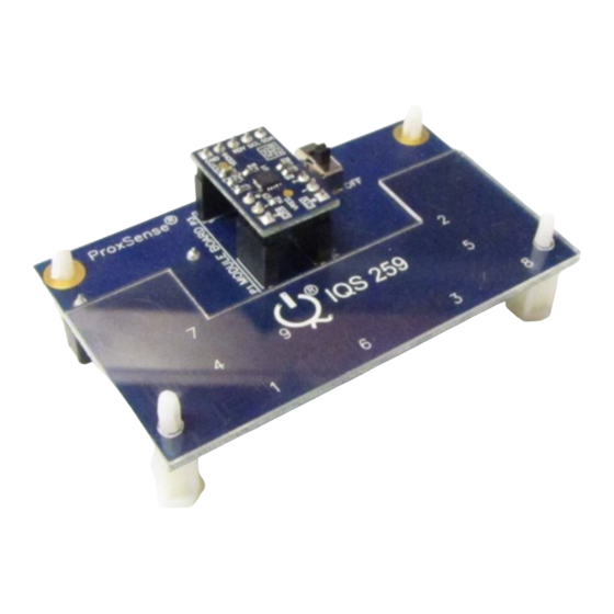
2 EV-Kit Mainboard
Figure
2.1
illustrates
mainboard and the supplied controller module.
The mainboard supplies power and other
functions to the controller module boards and
is easily operated. Simply plug in the desired
module board into the mainboard and turn on
the mainboard by means of the on/off slide
switch (if using battery or external power).
Features included in the EV-Kit mainboard:
Modular design: Connect the supplied IC
module into the mainboard, or wire into a
prototype for rapid prototyping
Reference design for IQS259 with user
proximity & touch detection ability
GUI interface indicates proximity AND
contact to the buttons
2
TM
I
C
Data Streaming Mode: For details,
see
the
IQS259
requires Azoteq Configuration Tool or
Data Streamer)
Copyright © Azoteq (Pty) Ltd 2012
All Rights Reserved.
IQ Switch
ProxSense
®
IQ Switch
- ProxSense
Table of Contents
the
evaluation
kit
datasheet
(EV-KIT
IQS259EV02 Evaluation Kit User Manual
®
®
Series
®
Series
Figure 2.1
IQS259EV02 Mainboard
and controller module
Figure 2.2 illustrates the bottom view of the
EV-Kit mainboard. The EV-Kit is powered by
the Azoteq CTxxx or optionally two 3V coin cell
batteries in series, which is regulated to 3.3V
and supplied to the module board. The EV-Kit
mainboard can also draw power from a USB
source by means of the mini-USB connector
provided on the mainboard.
USB
Power
Port
Figure 2.2
Bottom view of EV-Kit
mainboard
Revision 1.0
Programming
and data
streaming
header
Page 1 of 4
September 2012
Advertisement
Table of Contents

Related Manuals for Azoteq IQ Switch ProxSense IQS259EV02


Summary of Contents for Azoteq IQ Switch ProxSense IQS259EV02
- Page 1 EV-Kit mainboard. The EV-Kit is powered by the mainboard by means of the on/off slide the Azoteq CTxxx or optionally two 3V coin cell switch (if using battery or external power). batteries in series, which is regulated to 3.3V Features included in the EV-Kit mainboard: and supplied to the module board.
- Page 2 The EV-Kit is interfaced to a personal computer for data streaming, by means of the Power 1µF, C1, C2 Azoteq Configuration Tool (CTxxx). For visual supply 100pF data streaming please utilise the IQS259 GUI decoupling and USBProg software, provided on the capacitors Azoteq website.
- Page 3 CT200 Configuration Tool. The IQS259 GUI is necessary to interface the IQS259 module to a used to stream and visualize data in real-time. personal computer by means of the Azoteq Figure 4.1 IQS259 Graphical User Interface The IQS259 Software GUI can be downloaded from the following link: http://www.azoteq.com/images/stories/software...
- Page 4 Azoteq. The information in this Datasheet is believed to be accurate at the time of publication. Azoteq assumes no liability arising from the use of the information or the product. The applications mentioned herein are used solely for the purpose of illustration and Azoteq makes no warranty...
Need help?
Do you have a question about the IQ Switch ProxSense IQS259EV02 and is the answer not in the manual?
Questions and answers