Table of Contents
Advertisement
Quick Links
ÇALIŞTIRMA VE MONTAJ TALIMATLARI
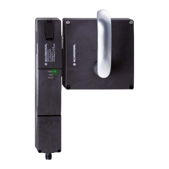
Solenoid interlock AZM201B-SK-T-1P2PW-DU
Table of Contents
1 About this document
1.1 Function
1 About this document
1.1 Function
This document provides all the information you need for the mounting, set-up and commissioning to ensure the safe
operation and disassembly of the switchgear. The operating instructions enclosed with the device must always be
kept in a legible condition and accessible.
1-22
Advertisement
Table of Contents

Related Manuals for schmersal AZM201B-SK-T-1P2PW-DU


Summary of Contents for schmersal AZM201B-SK-T-1P2PW-DU
-
Page 1: Table Of Contents
ÇALIŞTIRMA VE MONTAJ TALIMATLARI Solenoid interlock AZM201B-SK-T-1P2PW-DU Table of Contents 1 About this document 1.1 Function 1.2 Target group of the operating instructions: authorised qualified personnel 1.3 Explanation of the symbols used 1.4 Appropriate use 1.5 General safety instructions 2 Product description 2.1 Ordering code... -
Page 2: Target Group Of The Operating Instructions: Authorised Qualified Personnel
The user must observe the safety instructions in this operating instructions manual, the country specific installation standards as well as all prevailing safety regulations and accident prevention rules. Further technical information can be found in the Schmersal catalogues or in the online catalogue on the Internet: products.schmersal.com. -
Page 3: Product Description
2 Product description 2.1 Ordering code Ürün tip tanımı: AZM201(1)-(2)-(3)-T-(4)-(5) Kilitleme kontrol edilir aktüatör denetlenmiş Standart sürümde dahil edilmiştir kodlama Tek olarak kodlama Tek olarak kodlama, tekrar öğretilebilir Vida terminalleri Kafes kelepçeleri Konektör fişi M12 8-kutup 1P2PW 1 diyagnostik çıkış, p-tipi ve >2 emniyetli çıkış, p-tipi > (kombine edilmiş... -
Page 4: Purpose
2.3 Purpose The non-contact, electronic safety switchgear is designed for application in safety circuits and is used for monitoring the position and locking of movable safety guards. The safety switchgears are classified according to EN ISO 14119 as type 4 interlocking devices. Designs with individual coding are classified as highly coded. -
Page 5: Technical Data
work, arbitrary repairs, conversions and/or modifications to the device. 2.6 Technical Data Onaylar Verileri TÜV cULus Genel veriler Normlar, talimatlar EN ISO 13849-1 EN ISO 14119 EN IEC 60947-5-3 EN IEC 61508 genel bilgiler Evrensel Kodlama Coding level according to EN ISO 14119 düşük Etkili kural RFID... - Page 6 Normlar, talimatlar EN ISO 13849-1 EN IEC 61508 Güvenlik sınıflandırması - Kapalı tutma fonksiyonu Performance Level, up to Kontrol kategorisi PFH değeri 1,90 x 10⁻⁹ /h PFD değeri 1,60 x 10⁻⁴ Safety Integrity Level (SIL), suitable for applications in Mission time 20 Yıl(lar) Mekanik veriler Mekanik ömür, minimum...
- Page 7 Note (Cable section) Kablo kısmı hakkındaki bütün göstergeler iletken yüksüklerini dahil ediyor. Veya makine çapı, minimum 23 AWG Veya makine çapı, maximum 15 AWG Wire cross-section 23 ... 15 AWG Allowed type of cable solid single-wire solid multi-wire flexible Mekanik veriler - Boyutlar Sensörün boyu 50 mm Sensörün genişliği...
- Page 8 Rated operating voltage 24 VDC Çalışma akımı 1.200 mA N 60947-5-1 uyarınca koşullu nominal kısa devre akımı 100 A External wire and device fuse rating 4 A gG Hazır olma zamanı, maximum 4.000 ms Anahtarlama frekansı, maximum 1 Hz Elektriksel veriler - Bobin kontrollu IN Designation, Magnet control Mıknatıs girişlerinin anahtarlama eşikleri -3 V …...
- Page 9 Current, Utilisation category DC-13 0,25 A Test pulse interval, typical 1000 ms Test pulse duration, maximum 0,5 ms Classification ZVEI CB24I, Source Classification ZVEI CB24I, Sink Elektriksel veriler - Diyagnostik çıkış Designation, Diagnostic outputs Nominal çalışma akımı (teşhis çıkışı) 50 mA Design of control elements short-circuit proof, p-type Voltage drop U...
-
Page 10: Mounting
This device complies with the nerve stimulation limits (ISED CNR-102) when operated at a minimum distance of 100 In the event of changes or modifications that have not been expressly approved by K.A. Schmersal GmbH & Co. KG, the user's authorisation to use the device may become ineffective. -
Page 11: Dimensions
Mounting of the solenoid interlock and the actuator Refer to the mounting instructions manual for the corresponding actuator. The actuator must be permanently fitted to the safety guards and protected against displacement by suitable measures (tamperproof screws, gluing, drilling of the screw heads). Hilfsentriegelung Zur Aufstellung der Maschine kann die Sicherheitszuhaltung spannungslos entriegelt werden. -
Page 12: Electrical Connection
Legende A: Hilfsentriegelung B: Aktiver RFID-Bereich Metal parts and magnetic fields in the lateral RFID area of the solenoid interlock and the actuator can influence the switching distance or lead to malfunctions. Nachrüstsatz Notentsperrung/Fluchtentriegelung Der Nachrüstsatz dient der nachträglichen Funktionserweiterung der Sicherheitszuhaltung. Bezeichnung Bestellnummer Notentsperrung... -
Page 13: Serial Diagnostic -Sd
100 ms einzustellen. Die Sicherheitseingänge der Auswertung sollten einen Testimpuls von ca. 1 ms ausblenden können. Eine Querschlusserkennung in der Auswertung ist nicht notwendig und ist ggf. auszuschalten. Information for the selection of suitable safety-monitoring modules can be found in the Schmersal catalogues or in the online catalogue on the Internet: products.schmersal.com. -
Page 14: Wiring Configuration And Connector Accessories
The application examples shown are suggestions. They however do not release the user from carefully checking whether the switchgear and its set-up are suitable for the individual application. The application examples shown are suggestions. Anschlussbeispiel 1: Reihenschaltung AZM201 mit konventionellem Diagnoseausgang Bei der Reihenschaltung ist die Brücke 24V-X1-X2 aus allen Geräten bis auf das letzte Gerät zu entfernen. -
Page 15: Anlernen Der Betätiger / Betätigererkennung
Funktion Sicherheitsschaltgerät Pinbelegung Belegung der Farbcodes der Mögl. Farbcode abnehmbaren Schmersal- weiterer Einbausteckers Klemmleisten Steckverbinder handelsübliche ST2, M12, 8- gemäß DIN polig 47100 Steckverbinder gemäß EN 60947-5-2 konventionelle serieller Diagnosefunkti Diagnoseausga Sicherheitseingang 1 Sicherheitsausgang 1 Diagnoseausgang SD-Ausgang Sicherheitseingang 2... -
Page 16: Active Principle And Diagnostic Functions
3. After 10 seconds, brief yellow cyclic flashes (3 Hz) request the switch-off of the operating voltage of the solenoid interlock. (If the voltage is not switched off within 5 minutes, the solenoid interlock cancels the "teach-in" procedure and signals a false actuator by 5 red flashes). 4. - Page 17 be disabled within the duration of risk. After fault rectification, the error message is reset by opening and re-closing the corresponding safety guard. Automatic, electronic locking takes place if more than one fault is detected at the safety outputs or a cross circuit is detected between Y1 and Y2.
- Page 18 18-22...
- Page 19 Table 1: Diagnostic information of the safety switchgear System Diagnostic Magnet control IN Safety outputs Y1, Y2 condition output OUT Power to Power to green yellow AZM201Z AZM201B -1P2PW unlock lock Door open 24 V (0 V) 0 V (24 V) Door closed, 24 V actuator...
-
Page 20: Solenoid Interlock With Serial Diagnostic Function Sd
In this way, the diagnostic signals can be evaluated by means of a PLC. The necessary software for the integration of the SD-Gateway is available for download at products.schmersal.com. The response data and the diagnostic data are automatically and permanently written in an input byte of the PLC for each solenoid interlock in the series-wired chain. -
Page 21: Set-Up And Maintenance
Error warning A fault that does not immediately endanger the safety function of the safety switchgear (e.g. too high ambient temperature, safety output at external potential, cross-circuit) leads to delayed shutdown. This signal combination, diagnostic output disabled and safety channels still enabled, can be used to stop the production process in a controlled manner. -
Page 22: Disassembly And Disposal
22-22 Schmersal Turkey Otomasyon Ürünleri ve Hizmetleri Ltd. Şti., Atatürk Mah. Ataşehir Bulvarı No:5, 34758 Ataşehir Veriler ve ayrıntılar dikkatli bir şekilde kontrol edilmişlerdir. Görüntüler orijinalden farklı olabilir. Daha fazla teknik veri kılavuzda bulunabilir. Teknik değişiklikler ve hatalar olabilir.
Need help?
Do you have a question about the AZM201B-SK-T-1P2PW-DU and is the answer not in the manual?
Questions and answers