Table of Contents
Advertisement
Quick Links
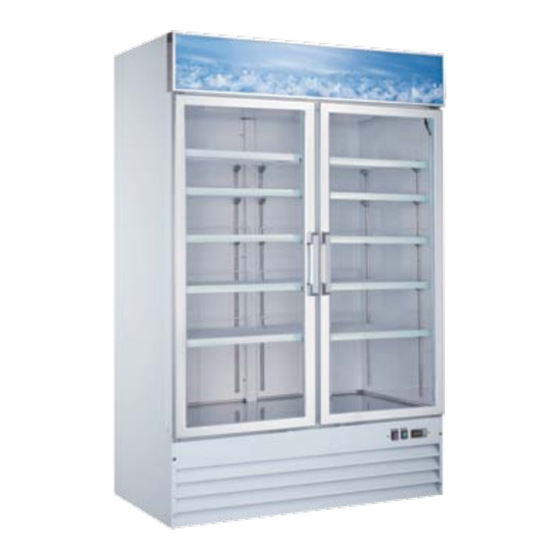
Glass Door Merchandisers
Models RE-CN-0045-HC, 0045-HC-BK, 0045-HC-SW, 0045-HC-SB, 0009-HC, 0009-HC-BK, 0014-H, 0014-HC-BK,
0023-HC, 0023-H, 0052-HC, 0052-HC-BK, FR-CN-0012-HC, 0790-HC, 1250-HC, 0045-HC, 0052-HC
Items 50032, 51032, 52032, 53032, 50033, 51033, 50035, 51035, 50036, 50037, 50052, 51052, 50029, 50030,
50031, 50075, 50087
Instruction Manual
Revised - 05/11/2023
Toll Free: 1-800-465-0234
Fax: 905-607-0234
Email: service@omcan.com
www.omcan.com
Advertisement
Table of Contents

Related Manuals for Omcan RE-CN-0045-HC-BK


Summary of Contents for Omcan RE-CN-0045-HC-BK
- Page 1 0023-HC, 0023-H, 0052-HC, 0052-HC-BK, FR-CN-0012-HC, 0790-HC, 1250-HC, 0045-HC, 0052-HC Items 50032, 51032, 52032, 53032, 50033, 51033, 50035, 51035, 50036, 50037, 50052, 51052, 50029, 50030, 50031, 50075, 50087 Instruction Manual Revised - 05/11/2023 Toll Free: 1-800-465-0234 Fax: 905-607-0234 Email: service@omcan.com www.omcan.com...
-
Page 2: Table Of Contents
Table of Contents Model RE-CN-0045-HC / Model RE-CN-0045-HC-BK / Model RE-CN-0045-HC-SW RE-CN-0045-HC-SB / Model RE-CN-0009-HC / Model RE-CN-0009-HC-BK Model RE-CN-0014-H / Model RE-CN-0014-HC-BK / Model RE-CN-0023-HC Model RE-CN-0023-H / Model RE-CN-0052-HC / Model RE-CN-0052-HC-BK Model FR-CN-0790-HC / Model FR-CN-1250-HC / Model FR-CN-0045-HC... -
Page 3: Disclaimer
D’huMIDITé relaTIve, eT sI le DraIn De l’appareIl n’esT pas raCCOrDé DIreCTeMenT à un DraIn De planCher. OMCan nO se haCe respOnsable De lOs DañOs CausaDOs pOr fuGas De aGua. la GaranTía pOr fuGas De aGua queDa anulaDa sI la TeMperaTura aMbIenTe supera lOs 75°f y el... -
Page 4: General Information
If the package has suffered rough handling, bumps or damage (visible or concealed), please note it on the bill of lading before accepting the delivery and contact Omcan within 24 hours, so we may initiate a claim with the carrier. A detailed report on the extent of the damage caused to the machine must be filled out within three days, from the delivery date shown in the shipping documents. -
Page 5: Safety And Warranty
Si el paquete ha sufrido un manejo de poco cuidado, golpes o daños (visible o oculto) por favor anote en la factura antes de aceptar la entrega y contacte Omcan dentro de las 24 horas, de modo que podamos iniciar una reclamación con la compañia. - Page 6 2 YEARS PARTS AND LABOUR / 5 YEARS PARTS ONLY ON COMPRESSOR WARRANTY Within the warranty period, contact Omcan Inc. at 1-800-465-0234 to schedule an Omcan authorized service technician to repair the equipment locally. Unauthorized maintenance will void the warranty. Warranty covers electrical and part failures, not improper use.
-
Page 7: Technical Specifications
Technical Specifications GLASS DOOR COOLERS Model RE-CN-0045-HC RE-CN-0045-HC-BK RE-CN-0045-HC-SW RE-CN-0045-HC-SB Color White Black White Black Temperature Range 0 - 5°C / 33 - 41°F Max Ambient Temp 24°C / 75°F Rating Power 1/4 HP Electrical 110-120V / 60Hz / 1 Current 4.3A... - Page 8 Technical Specifications Model RE-CN-0023-HC RE-CN-0023-H RE-CN-0052-HC RE-CN-0052-HC-BK Color White Black White Black Temperature Range 0 - 5°C / 33 - 41°F Max Ambient Temp 24°C / 75°F Rating Power 1/5 HP 3/4 HP Electrical 110-120V / 60Hz / 1 Current 10.7A Refrigerant R290...
- Page 9 Technical Specifications GLASS DOOR FREEzERS Model FR-CN-0012-HC FR-CN-0790-HC FR-CN-1250-HC Color White Temperature Range -23 to -18°C / -10 to -0.4°F Max Ambient Temp 24°C / 75°F Rating Net Volume 368 L / 13 cu. ft. 648 L / 23 cu. ft. 821 L / 29 cu.
-
Page 10: Installation
Installation IMPORTANT!!!PLEASE READ BEFORE INSTALLATION • The refrigeration system operates most efficiently when installed in an area with cool, dry air circulation. • There must be at least 6 inches of clearance on both sides and the back of the cabinet. •... -
Page 11: Controller Instructions
Troubleshooting Poor Performance Move the unit from direct sun light, and avoid installing heating devices near the unit. Install the unit in a well ventilated place with minimum of 6” clearance in the back. Check the condenser, and clean if heavy dust is collected. - Page 12 Controller Instructions Display and functions During normal operation, the controller displays the value of the probe set using parameter/4(=1 ambient probe, default, = 2 second probe, = 3 third probe).In addition, the display has LEDs that indicate the activation of the control functions (see Table 1), while the 3 buttons can be used to activate/deactivate some of the functions(see Table 2).
- Page 13 Controller Instructions Press UP for more than 3 sec. The control and defrost algorithms are now disabled and the Instrument displays the message “OFF” alternating with the temperature read by the set probe. Manual defrost Press for DOWN more than 3 sec (the defrost starts only the temperature conditions are valid). Continuous cycle Press UP and DOWN together for more than 3 sec.
- Page 14 Controller Instructions Signals on the display The blinking status indicates a request for activation that cannot be implemented until the end of the Corresponding delay times. Icon Function Blink Startup Compressor Compressor on Compressor off Request Fan on Fan off Request Defrost Defrost in progress...
- Page 15 Controller Instructions Continuous cycle Pressing the buttons “ ” and “ ” simultaneously for more than 5 seconds enables the continuous cycle function. During operation in continuous cycle, the compressor continues to operate for the time “cc” and it stops when it reaches the “cc” time out or the minimum temperature has been reached(AL = minimum temperature alarm threshold).
- Page 16 Controller Instructions Saving the new values assigned to the parameters To definitely save the new values of the modified parameters, press the “ ” button for more than 5 seconds, thus exiting the parameter setting procedure. All the modification made to the parameters temporarily saved in the RAM, can be cancelled and “normal operation”...
-
Page 17: Parts Breakdown
Model re-Cn-0045-hC 50032 Model re-Cn-0045-hC-bk 51032... - Page 18 parts breakdown Model re-Cn-0045-hC 50032 Item No. Description Position Item No. Description Position Item No. Description Position AA766 Left Glass Door for 50032 AA809 K Strip for 50032 AB595 Filter Fixer for 50032 AA767 Front Grill Fixer for 50032 AA779 Shelf for 50032 AB594 Filter D25x160-B for 50032...
- Page 19 Model re-Cn-0045-hC-bk 51032 Item No. Description Position Item No. Description Position Item No. Description Position AA766 Left Glass Door for 51032 AA809 K Strip for 51032 AB595 Filter Fixer for 51032 AA767 Front Grill Fixer for 51032 AA779...
- Page 20 parts breakdown Model re-Cn-0045-hC-sw 52032 Model re-Cn-0045-hC-sb 53032...
- Page 21 parts breakdown Model re-Cn-0045-hC-sw 52032 Item No. Description Position Item No. Description Position Item No. Description Position AG557 Parts of Compressor for 52032 AN128 Left Shelf for 52032 AB966 Upper Right Hinge Holder for 52032 AE915 Compressor (T6217Z) for 52032 AE884 Light Box Plate for 52032 AN137...
- Page 22 parts breakdown Model re-Cn-0045-hC-sb 53032 Item No. Description Position Item No. Description Position Item No. Description Position AG557 Parts of Compressor for 53032 AN128 Left Shelf for 53032 AB966 Upper Right Hinge Holder for 53032 AE915 Compressor (T6217Z) for 53032 AE884 Light Box Plate for 53032 AN137...
- Page 23 parts breakdown Model re-Cn-0009-hC 50033 Model re-Cn-0009-hC-bk 51033...
- Page 24 parts breakdown Model re-Cn-0009-hC 50033 Item No. Description Position Item No. Description Position Item No. Description Position AE895 Castor Supporter for 50033 AB974 Handle for Installation Board for 50033 AA705 Condenser Fan Motor for 50033 Right Track for Installation Board for AE896 AE900 K Strip for 50033...
- Page 25 parts breakdown Model re-Cn-0009-hC-bk 51033 Item No. Description Position Item No. Description Position Item No. Description Position AE895 Castor Supporter for 51033 AB974 Handle for Installation Board for 51033 AA705 Condenser Fan Motor for 51033 Right Track for Installation Board for AE896 AE900 K Strip for 51033...
- Page 26 parts breakdown Model re-Cn-0014-h 50035 Model re-Cn-0014-hC-bk 51035...
- Page 27 parts breakdown Model re-Cn-0014-h 50035 Item No. Description Position Item No. Description Position Item No. Description Position AE907 Castor Supporter for 50035 AE911 K Strip for 50035 AB594 Filter for 50035 Right Track for Installation Board for AE896 26884 K Clip for 50035 AB595 Filter Fixer for 50035 50035...
- Page 28 parts breakdown Model re-Cn-0014-hC-bk 51035 Item No. Description Position Item No. Description Position Item No. Description Position AE907 Castor Supporter for 51035 AE911 K Strip for 51035 AB594 Filter for 51035 Right Track for Installation Board for AE896 26884 K Clip for 51035 AB595 Filter Fixer for 51035 51035...
- Page 29 parts breakdown Model re-Cn-0023-hC 50036 Model re-Cn-0023-h 50037...
- Page 30 parts breakdown Model re-Cn-0023-hC 50036 Item No. Description Position Item No. Description Position Item No. Description Position Right Track for Installation Board for Right Bracket for Evaporator Fan Cover AB953 AA748 Shelf Tag for 50036 AA793 50036 for 50036 AB954 Castor Supporter for 50036 AA722 LED Light for 50036...
- Page 31 parts breakdown Model re-Cn-0023-h 50037 Item No. Description Position Item No. Description Position Item No. Description Position Right Track for Installation Board for Right Bracket for Evaporator Fan Cover AB953 AA748 Shelf Tag for 50037 AA793 50037 for 50037 AB954 Castor Supporter for 50037 AA722 LED Light for 50037...
- Page 32 parts breakdown Model re-Cn-0052-hC 50052 Model re-Cn-0052-hC-bk 51052...
- Page 33 parts breakdown Model re-Cn-0052-hC 50052 Item No. Description Position Item No. Description Position Item No. Description Position 61219 Evaporator Fan Blade V154/22 for 50052 AE919 Air Pipe Protection Board for 50052 AA837 Light Box Plate for 50052 Evaporator Fan Motor EM3020-28-C04 / 68809 AA715 Axis Cover for 50052...
- Page 34 parts breakdown Model re-Cn-0052-hC-bk 51052 Item No. Description Position Item No. Description Position Item No. Description Position 61219 Evaporator Fan Blade V154/22 for 51052 AE919 Air Pipe Protection Board for 51052 AA837 Light Box Plate for 51052 Evaporator Fan Motor EM3020-28-C04 / 68809 AA715 Axis Cover for 51052...
- Page 35 parts breakdown Model fr-Cn-0012-hC 50029...
- Page 36 parts breakdown Model fr-Cn-0012-hC 50029 Item No. Description Position Item No. Description Position Item No. Description Position AA848 Gasket for 50029 AA857 Upper Right Hinge Holder for 50029 AA874 Outer Drain Pan for 50029 AA807 Bottom Right Hinge Holder for 50029 AA695 Glass Door Handle for 50029 AE938...
- Page 37 parts breakdown Model fr-Cn-0790-hC 50030...
- Page 38 parts breakdown Model fr-Cn-0790-hC 50030 Item No. Description Position Item No. Description Position Item No. Description Position AE943 Castor Installation Board for 50030 AB974 Handle for Installation Board for 50030 AE926 Thermostat Installation Plate for 50030 26247 Caster without Brake for 50030 AA856 Power Cord for 50030 AE946...
- Page 39 parts breakdown Model fr-Cn-1250-hC 50031...
- Page 40 parts breakdown Model fr-Cn-1250-hC 50031 Item No. Description Position Item No. Description Position Item No. Description Position AA927 Power Cord for 50031 AB978 Left Rail for Installation Board for 50031 AE955 Air Pipe Protection Board for 50031 AA124 Power Switch for 50031 AB134 Condenser for 50031 AA939...
- Page 41 parts breakdown Model fr-Cn-0045-hC 50075...
- Page 42 parts breakdown Model fr-Cn-0045-hC 50075 Item No. Description Position Item No. Description Position Item No. Description Position AE881 Back Grill for 50075 AA854 Shelf Tag for 50075 AE963 Air Pipe Protection Board for 50075 AA216 Drain Tube for 50075 AA249 Condenser Fan Motor Cover for 50075 AA787 LED Power Supply for 50075...
- Page 43 parts breakdown Model fr-Cn-0052-hC 50087...
- Page 44 parts breakdown Model fr-Cn-0052-hC 50087 Item No. Description Position Item No. Description Position Item No. Description Position AA743 4” Caster without Brake for 50087 AA929 Left Glass Door for 50087 AA703 Power Cord Cover for 50087 AA584 Caster with Brake for 50087 AA695 Glass Door Handle for 50087 AA216...
-
Page 45: Electrical Schematics
Model re-Cn-0045-hC 50032 Model re-Cn-0045-hC-bk 51032 Model re-Cn-0045-hC-sw 52032 Model re-Cn-0045-hC-sb 53032... - Page 46 electrical schematics Model re-Cn-0009-hC 50033 Model re-Cn-0009-hC-bk 51033...
- Page 47 electrical schematics Model re-Cn-0014-h 50035 Model re-Cn-0014-hC-bk 51035...
- Page 48 electrical schematics Model re-Cn-0023-hC 50036 Model re-Cn-0023-h 50037...
- Page 49 electrical schematics Model re-Cn-0052-hC 50052 Model re-Cn-0052-hC-bk 51052...
- Page 50 electrical schematics Model fr-Cn-0012-hC 50029...
- Page 51 electrical schematics Model fr-Cn-0790-hC 50030...
- Page 52 electrical schematics Model fr-Cn-1250-hC 50031...
- Page 53 electrical schematics Model fr-Cn-0045-hC 50075...
- Page 54 electrical schematics Model fr-Cn-0052-hC 50087...
-
Page 55: Warranty Registration
Thank you for purchasing an Omcan product. To register your warranty for this product, complete the information below, tear off the card at the perforation and then send to the address specified below. You can also register online by visiting: Merci d’avoir acheté... - Page 56 Since 1951 Omcan has grown to become a leading distributor of equipment and supplies to the North American food service industry. Our success over these many years can be attributed to our commitment to strengthen and develop new and existing relationships with our valued customers and manufacturers.
Need help?
Do you have a question about the RE-CN-0045-HC-BK and is the answer not in the manual?
Questions and answers