Table of Contents
Advertisement
Quick Links
INSTALLATION INSTRUCTIONS
CONTENTS
SAVE THESE INSTRUCTIONS FOR FUTURE REFERENCE
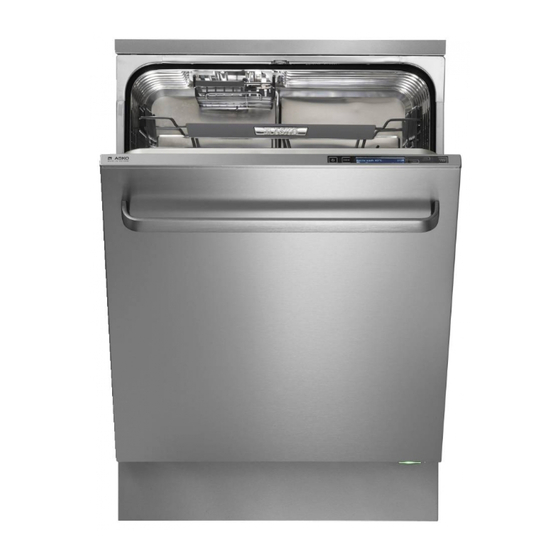
FI DISHWASHER
AUTOMATIC HIGH LOOP
The drain hose is fastened to the back of
the machine at the best height. To eliminate
potential drain problems, leave this hose in
place.
2
2
2
4
4
4
5
5
5
6
7
11
13
15
15
17
19
Advertisement
Table of Contents

Related Manuals for Asko D5894XXLFI


Summary of Contents for Asko D5894XXLFI
-
Page 1: Table Of Contents
FI DISHWASHER INSTALLATION INSTRUCTIONS AUTOMATIC HIGH LOOP The drain hose is fastened to the back of the machine at the best height. To eliminate potential drain problems, leave this hose in place. CONTENTS INTRODUCTION WHAT YOU NEED SAFETY INSTRUCTIONS XXL DISHWASHERS UNIT DIMENSIONS PREPARING THE LOCATION ADA DISHWASHERS... -
Page 2: Introduction
NOTE: If a dishwasher is being installed in this area for the first Cosmetic damage must be reported to the ASKO time, most of the cabinet work, plumbing, and electrical dealer within five days from the date of purchase. -
Page 3: Safety Instructions
SAFETY INSTRUCTIONS BEFORE STARTING THE INSTALLATION: • It is important that you closely follow the instructions provided here. Connection to water supply: • An incorrect or defective installation can lead to • There must be a shut off valve on the water supply pipe. higher consumption of energy, water and dishwashing The shut off valve should be installed in a location that detergent, which can lead to higher costs and poor... -
Page 4: Xxl Dishwashers
XXL DISHWASHERS D5524XXLFI, D5534XXLFI, D5554XXLFI, D5894XXLFI UNIT DIMENSIONS Technical Data U.S. Metric Electricity 120V, 60Hz, 15 amp Height (Adjustable) 33-7/8˝ to 36˝ 860 mm to 914 mm Water pressure 4.2 - 140 psi, Width 23-5/8˝ 600 mm 0.03-1.0 MPa, Depth (Includes high loop) 22-7/8˝... -
Page 5: Ada Dishwashers
ADA DISHWASHERS D5534ADAFI UNIT DIMENSIONS Technical Data U.S. Metric Electricity 120V, 60Hz, 15 amp Height (Adjustable)* 32-1/4˝ to 34˝ 819 mm to 864 mm Water pressure 4.2 - 140 psi, Width 23-5/8˝ 600 mm 0.03-1.0 MPa, Depth (Includes high loop) 22-7/8˝... -
Page 6: Adafi Trim Kit Installation Options
ADAFI TRIM KIT INSTALLATION OPTIONS ASKO XLADAFI dishwashers can be installed either with or without accessory fill strips depending on the type of installation. If the dishwasher cutout has been cut to European widths of 23-5/8˝ (600 mm), the unit won’t require fill strips. If the dishwasher cutout is a standard 24˝... -
Page 7: Step 1. Fitting The Dishwasher In Place
STEP 1. FITTING THE DISHWASHER IN PLACE Attach the light shielding film (packed in the document bag) to the underside of the countertop above the touch buttons. (Only certain models). The light shielding film ensures optimal button functionality. NOTE: The surface on which the protective film is to be attached must be clean and dry. - Page 8 STEP 1. FITTING THE DISHWASHER IN PLACE Adjust the height of the dishwasher by turning the steel feet with your hands. Leave enough space to adjust them later. Screw in the back foot completely by turning the adjustment screw at the front counterclockwise. Use a flat-bladed screwdriver or a 1/4˝...
- Page 9 STEP 1. FITTING THE DISHWASHER IN PLACE 10. Check that the height of the machine corresponds to the height from the floor to the bottom edge of the counter top. Do not attach the mounting screws. This will be done later. 11.
-
Page 10: Step 2. Attaching The Accessory Door Or Custom Panel
STEP 2. ATTACHING THE ACCESSORY DOOR OR CUSTOM PANEL Follow the separate instructions supplied with the dishwasher to attach the chosen accessory door or custom panel to the front of the machine. NOTE: Once you have fitted the accessory door or custom panel to the dishwasher, the door springs may need adjusting. -
Page 11: Step 3. Adjusting The Door Springs
STEP 3. ADJUSTING THE DOOR SPRINGS TYPE A TYPE B (SEE PAGE 12) TYPE A The door springs are on the sides of the dishwasher. If necessary, pull out the dishwasher and adjust the tension of the door springs. A good idea is to try adjusting one side only first. - Page 12 STEP 3. ADJUSTING THE DOOR SPRINGS Replace the back end of the spring by holding the spring at a right angle to the side of the dishwasher and pushing the end of the spring into the hole, then turning the spring in towards the dishwasher. Reattach the front end of the spring by pulling it up and forward to fasten it in the mount.
-
Page 13: Step 4. Connecting Electricity, Water, And Drain
CONNECT DRAIN HOSE THREE WAYS TO INSTALL DRAIN CONNECTIONS ASKO provides a 7/8˝ (22 mm) diameter corrugated drain hose which is connected to the back of the unit to form a high loop. A) Typical connection to sink plumbing before... - Page 14 STEP 4. CONNECTING ELECTRICITY, WATER, AND DRAIN 2. CONNECT WATER SUPPLY HOSE In order to prevent heat damage to the inlet valve, all solder connections must be made before the water supply line is connected. Flush the water supply line prior to connecting it to the water fill tube.
-
Page 15: Step 5. Checking Dishwasher Function And Fit
STEP 5. CHECKING DISHWASHER FUNCTION AND FIT Test the dishwasher with the Rinse & Hold program. Check that the dishwasher fills and drains properly. Also check that none of the connections leak. Also check that adjacent drawers and cabinet doors can be opened when the dishwasher door is open. - Page 16 STEP 6. SECURING THE DISHWASHER Check that the dishwasher’s steel feet are solidly placed on the floor. Make sure the dishwasher is not hanging in the air by the mounting tabs. If it is, turn the front feet to lower them until the machine is resting on the feet.
-
Page 17: Step 7. Attaching The Toe Kick (If Applicable)
STEP 7. ATTACHING THE TOE KICK (IF APPLICABLE) TYPE A TYPE B TYPE A The toe kick is attached with two screws that can only be adjusted vertically. TYPE B Attach the supplied sound insulation material to the back of the toe kick. (Only for certain models.) Loosen the holders for the toe kick by moving the gray catches to the side. - Page 18 STEP 7. ATTACHING THE TOE KICK (IF APPLICABLE) Hang the toe kick on the holders. Check that the toe kick is flush with the surrounding kitchen toe kick. If not, loosen and adjust the holders as necessary until satisfied. Page 18 Customer Care Center 1-800-898-1879 www.askousa.com...
-
Page 19: Installation Checklist
INSTALLATION CHECKLIST ASKO - DISHWASHER Appliance Installation Checklist • Remove packaging and check for cosmetic damages. • Remove the information packets from inside the dishwasher. • Attach any accessories as required by the installation. Fill strips, light shielding film, supplied door sealing, accessory door, custom panel... - Page 20 Art. No 8092459 Rev. 01 Page 20 Customer Care Center 1-800-898-1879 www.askousa.com...
Need help?
Do you have a question about the D5894XXLFI and is the answer not in the manual?
Questions and answers