
Related Manuals for Gigamon G-TAP M Series


Summary of Contents for Gigamon G-TAP M Series
- Page 1 G-TAP M Series Hardware Guide GigaVUE M Series Product Version: 2.3.01 and above Document Version: 1.0 (See Change Notes for document updates.)
- Page 2 Gigamon Inc.. Trademark Attributions Gigamon and the Gigamon logo are trademarks of Gigamon in the United States and/or other countries. Gigamon trademarks can be found at www.gigamon.com/legal- trademarks.
- Page 3 G-TAP M Series Hardware Guide Contents About This Guide Installing and Removing G-TAP M Series Modules Installing G-TAP M Series Modules in a G-TAP M Series Chassis Removing G-TAP M Series Modules Connecting G-TAP M Series Modules Disconnecting Fiber from the Modules...
-
Page 4: About This Guide
The number of modules that can be installed in a G-TAP M Series chassis are: ■ Up to six modules can be installed in a G-TAP M Series TAP-M200, which is a 1 Rackmount Unit (RU) chassis. Up to three modules can be installed in a G-TAP M Series TAP-M100T, which is a 1/2 RU chassis. - Page 5 Installing G-TAP M Series Modules in a G-TAP M Series Chassis To install G-TAP M Series modules in a G-TAP M Series chassis, do the following: Install the G-TAP M Series chassis in a rack. Following figures show examples of 1RU G-TAP M Series TAP-M200 chassis, TAP-M202ULT chassis, and 1/2RU G-TAP M Series TAP-M100T chassis that are empty.
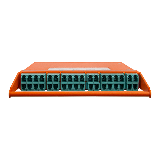
- Page 6 LC Duplex or MPO/MTP connectors are easily accessed when connected to the module. Merely pull the TAP module out of the G-TAP M Series chassis by 3in or 4in. This alleviates the need for special connector latches or extraction tools.
- Page 7 G-TAP M Series Hardware Guide Figure Figure 8Routing Diagram for Fused Type TAPs shows the routing diagram that is on the top panel of the Fused type G-TAP models. Refer to the Connecting G-TAP M Series Modules for the list of Fused TAPs.
- Page 8 G-TAP M Series Hardware Guide Figure 11 Routing Diagram for Breakout Panels PNL-M341, PNL-M341T, PNL-M343, and PNL-M343T Port Labels Figure Figure 12Port Label for G-TAP M251, M 251T, M253T, M271, M271T, M273, M273T, M453, and M473 shows the port label that is on the top panel of G-TAP models M251, M251T, M253T, M271, M271T, M273, M273T, M453, and M473.
- Page 9 M343T Connecting G-TAP M Series Breakout Panels Breakout panels are used to breakout single ports to multiple ports or to aggregate multiple ports to a single port. There are two G-TAP M Series breakout panels available: PNL-M341 ■ PNL-M343 ■...
- Page 10 G-TAP M Series Hardware Guide The PNL-M341 breakout panel contains three breakout modules labeled A, B, and C, and can be used for the breakout of a 40Gb port to four 10Gb links or for the aggregation of four 10Gb links to a 40Gb port, or for the breakout of a 100Gb port to four 25Gb links or for the aggregation of four 25Gb links to a 100Gb port.
- Page 11 G-TAP M Series Hardware Guide MPO and LC Connectors and Cabling The PNL-M341 breakout panel has three MPO connectors, each going to four LC duplexes. The MPO ports are MTP (UPC with pin-male), aqua color. The LC ports are LC (UPC), aqua color.
- Page 12 G-TAP M Series Hardware Guide Figure 22 PNL-M343 Connected to a TA10 for Aggregation MPO and LC Connectors and Cabling The PNL-M343 breakout panel has three MPO connectors, each going to four LC duplexes. The MPO ports are MTP (APC with pin-male), green color. The LC ports are LC (UPC), blue color.
-
Page 13: Features And Benefits
Capabilities do not conform to established protocol standards enabling detailed analysis, security, and monitoring. The G-TAP M Series modules rely on passive full duplex fiber optic splitters, Completely Passive TAP which results in non-point-of-failure operation. It requires no power source to operate. - Page 14 G-TAP M Series Hardware Guide Table 2: MM, SR TAP Modules describes the MM, SR TAP modules. Table 2: MM, SR TAP Modules G-TAP Speed Split Connector Mounting Fiber Ratio Network Chassis Type Series Loss Loss Module TAP-M251 1G/10G 50/50 3.9dB...
- Page 15 G-TAP M Series Hardware Guide G-TAP Speed Split Connector Mounting Fiber Ratio Network Chassis Type Series Loss Loss Module TAP-M471T 40G/100G 70/30 2.8dB 6.4dB MPO/MTP TAP- (UPC) M100T/TAP- M200 TAP- 40G/100G 70/30 2.8dB 7.4dB MPO/MTP TAP- M471ULT (UPC) M202ULT TAP-...
- Page 16 G-TAP M Series Hardware Guide G-TAP Speed Split Connect Mountin Fiber Rati Networ Type Series k Loss Chassis Modul M273 M100T/TA P-M200 TAP- 1G/10G/25G/40G/100G/ 70/30 2.0dB 6.1dB LC (UPC) TAP- M273T 400G Base M100T/TA P-M200 TAP- 1G/10G/25G/40G/100G/ 70/30 2.0dB 6.1dB...
-
Page 17: Electrical Characteristics
Full: 12.2lbs (5.5kg) TAP Module 0.84in 5.38in 8.94in 1.4lbs (2.14cm) (13.7cm) (22.7cm) (0.64kg) Breakout Panel 0.84in 5.38in 8.94in 1.4lbs (2.14cm) (13.7cm) (22.7cm) (0.64kg) Electrical Characteristics G-TAP M Series TAP Module Specifications describes the electrical characteristics of the G-TAP M Series modules. Contents... - Page 18 G-TAP M Series Hardware Guide Table 7: Electrical Characteristics of the G-TAP M Series Modules Type Specification Power Requirements Not Applicable. The G-TAP M Series modules are passive. Link TAP Capacity Each module taps up to six duplex links (three for MPO cabling).
- Page 19 G-TAP M Series Hardware Guide Common Issues Description Troubleshooting Tips means that the light is not passing through the cable. The transceiver type used on Ensure that the transceiver type is identical Mismatched both ends of the connection is on both ends of the connection. For example, transceivers not identical.
- Page 20 G-TAP M Series Hardware Guide Contents...
-
Page 21: Best Practices
G-TAP M Series Hardware Guide Figure 23 Troubleshoot Generic TAP Issues Best Practices When connecting TAPs, ensure you adhere to the following best practices: Prior to connecting any cable, both the port and cable adapter must be cleaned as ■... -
Page 22: Additional Sources Of Information
Documentation Downloads download all PDFs. Table 1: Documentation Set for Gigamon Products GigaVUE M Series 2.3.01 and above Hardware and Software Guides ? If you keep all PDFs for a release in common folder, you can easily search across the doc set ID YOU KNOW by opening one of the files in Acrobat and choosing Edit >... - Page 23 G-TAP M Series Hardware Guide GigaVUE M Series 2.3.01 and above Hardware and Software Guides GigaVUE-TA10 Hardware Installation Guide GigaVUE-TA40 Hardware Installation Guide GigaVUE-TA100 Hardware Installation Guide GigaVUE-TA100-CXP Hardware Installation Guide GigaVUE-OS Installation Guide for DELL S4112F-ON G-TAP A Series 2 Installation Guide...
- Page 24 GigaVUE-OS CLI (Command Line Interface) commands used to configure and operate GigaVUE HC Series and TA Series devices GigaVUE-OS Cabling Quick Reference Guide guidelines for the different types of cables used to connect Gigamon devices GigaVUE-OS Compatibility and Interoperability Matrix compatibility information and interoperability requirements for Gigamon devices GigaVUE-FM REST API Reference in GigaVUE-FM User's Guide...
-
Page 25: Documentation Feedback
Product: "GigaVUE-FM" and Release: "5.6," enter "pdf" in the search box, and then click GO to view all PDF documentation for GigaVUE-FM 5.6.xx. : My Gigamon is available to registered customers only. Newer documentation PDFs, with the exception of release notes, are all available through the publicly available online documentation. -
Page 26: Contact Technical Support
> Support > Contact Support in GigaVUE-FM. You can also refer to https://www.gigamon.com/support-and-services/contact-support Technical Support hours and contact information. Email Technical Support at support@gigamon.com. Contact Sales Use the following information to Gigamon channel partner or Gigamon sales representatives. Telephone: +1.408.831.4025 Additional Sources of Information... - Page 27 ■ Download the latest product updates and documentation (Customers only) ■ The Gigamon Community is a great way to get answers fast, learn from experts and collaborate directly with other members around your areas of interest. Register today at community.gigamon.com Questions? Contact our Community team at community@gigamon.com.
- Page 28 G-TAP M Series Hardware Guide Glossary decrypt list need to decrypt (formerly blacklist) decryptlist need to decrypt - CLI Command (formerly blacklist) drop list selective forwarding - drop (formerly blacklist) forward list selective forwarding - forward (formerly whitelist) leader leader in clustering node relationship (formerly master)
- Page 29 G-TAP M Series Hardware Guide nodecryptlist no need to decrypt- CLI Command (formerly whitelist) primary source root timing; transmits sync info to clocks in its network segment (formerly grandmaster) receiver follower in a bidirectional clock relationship (formerly slave) source leader in a bidirectional clock relationship (formerly master)
Need help?
Do you have a question about the G-TAP M Series and is the answer not in the manual?
Questions and answers