Gigamon GigaVUE H Series Hardware Installation Manual
Hide thumbs
Also See for GigaVUE H Series:
- Hardware installation manual (132 pages) ,
- Installation manual (83 pages) ,
- Installation manual (82 pages)

Related Manuals for Gigamon GigaVUE H Series


Summary of Contents for Gigamon GigaVUE H Series
-
Page 1: Gigavue-Hc3 Hardware Installation Guide
GigaVUE-HC3 Hardware Installation Guide GigaVUE H Series Product Version: 5.16 Document Version: 1.0 (See Change Notes for document updates.) - Page 2 Gigamon Inc.. Trademark Attributions Gigamon and the Gigamon logo are trademarks of Gigamon in the United States and/or other countries. Gigamon trademarks can be found at www.gigamon.com/legal- trademarks.
-
Page 3: Change Notes
GigaVUE-HC3 Hardware Installation Guide Change Notes When a document is updated, the document version number on the cover page will indicate a new version and will provide a link to this Change Notes table, which will describe the updates. Product Document Date Change Notes... -
Page 4: Table Of Contents
GigaVUE-HC3 Hardware Installation Guide Contents GigaVUE-HC3 Hardware Installation Guide Change Notes Contents About the GigaVUE H Series and TA Series Introducing the GigaVUE-HC3 Chassis GigaVUE-HC3 Overview GigaVUE-HC3 Control Cards Control Card Version 1 (CCv1) Control Card Version 2 (CCv2) GigaVUE-HC3 Extension Board Dual BIOS Images Software Upgrade Using USB Drive Chassis Cooling Air Flow Direction... - Page 5 Module Installation Procedure Removing GigaVUE-HC3 Modules Module Removal and Replacement Procedure (Hot Removal) Next Steps Basic GigaVUE H Series Connections and Configuration Grounding the GigaVUE-HC3 Chassis Connecting Power to the GigaVUE-HC3 Removing a Power Supply Module Connecting -48V DC Power Supply Modules...
- Page 6 GigaVUE-HC3 Hardware Installation Guide Entering Commands in the CLI Command-Line Syntax – Entering Commands The Basic Commands Completing the Initial GigaVUE H Series H Series Setup Enter the Configure Command-Line Mode SSH2 Enabling the GigaVUE H Series H Series Web Server Initial User Account Configuration Configuring the GigaVUE H Series H Series Host Name...
- Page 7 Bonding of Battery Return (BR) Input Terminals Connections Input AC/DC Voltage Maintenance Additional Sources of Information Documentation How to Download Software and Release Notes from My Gigamon Documentation Feedback Contact Technical Support Contact Sales Premium Support The Gigamon Community Glossary...
-
Page 8: About The Gigavue H Series And Ta Series
GigaVUE-HC3 Hardware Installation Guide About the GigaVUE H Series and TA Series The Gigamon Visibility and Analytics Fabric delivers unprecedented switching capacity, port density, and 1Gb/10Gb/40Gb/100Gb support. The GigaVUE H Series and TA Series include the following models that run GigaVUE-OS: GigaVUE-HC1 ■... -
Page 9: Introducing The Gigavue-Hc3 Chassis
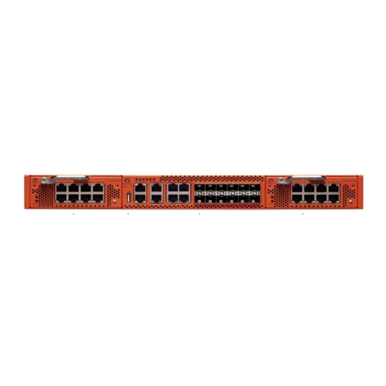
GigaVUE-HC3 Hardware Installation Guide Introducing the GigaVUE-HC3 Chassis The fully-assembled GigaVUE-HC3 chassis consists of a 3RU, rack-mountable, 19in-wide chassis with management, network, and tool ports at the front and power connections, fans, and access to the control card at the rear. GigaSMART is available with SMT-HC3-C05 installed in the chassis. - Page 10 GigaVUE-HC3 Hardware Installation Guide Figure 1 Front View of the GigaVUE-HC3 Chassis Figure 2 Rear View of the GigaVUE-HC3 Chassis Table 1: GigaVUE-HC3 Chassis Bays and Components Front Components on the GigaVUE-HC3 Chassis Module Bays There are four module bays. They are numbered from 1 to 4, starting with top left, then bottom left;...
-
Page 11: Gigavue-Hc3 Overview
GigaVUE-HC3 Hardware Installation Guide Front Components on the GigaVUE-HC3 Chassis board provides a USB port, console port, a management port, a PTP port, two stack ports, a P/S port and a PPS (IN) port, as well as status LEDs. Refer to GigaVUE-HC3 Extension Board for more information. -
Page 12: Gigavue-Hc3 Control Cards
GigaVUE-HC3 Hardware Installation Guide GigaVUE-HC3 GigaVUE-HC3 3RU Footprint ■ Four Module Slots ■ (Bays) Internal Control Card ■ Extension Board ■ Dedicated Cluster ■ Management Port Supports all ■ GigaVUE-HC3 Modules Cluster with ■ GigaVUE H Series H Series and GigaVUE H Series TA Series Nodes All ports, excluding... -
Page 13: Control Card Version 2 (Ccv2)
GigaVUE-HC3 Hardware Installation Guide Control Card Version 2 (CCv2) Control card version 2 (CCv2) supports the same modules as CCv1, as well as the following module: PRT-HC3-C16 ■ SMT-HC3-C08 ■ In addition, CCv2 supports the following: 25Gb optics on the 10Gb ports on the PRT-HC3-X24, BPS-HC3-C25F2G, BPS-HC3- ■... - Page 14 GigaVUE-HC3 Hardware Installation Guide Figure 3 GigaVUE-HC3 Extension Board Table 2: Extension Board Ports and LEDs LED Color Description USB Port — Upgrade software on the GigaVUE-HC3 using a software image on an external USB drive. CON Port — Configure the GigaVUE-HC3 locally over a serial terminal connection (RJ-45 console port).
- Page 15 GigaVUE-HC3 Hardware Installation Guide LED Color Description MGMT Port — Configure the GigaVUE-HC3 remotely over a SSH connection (RJ-45 management port, 10/100/1000BASE-T). PTP Port — In GigaVUE-HC3 Control Card Version 1 (CCv1), the PTP port is used a eth1. In GigaVUE-HC3 Control Card Version 2 (CCv2), the PTP port is reserved for future use.
-
Page 16: Dual Bios Images
GigaVUE-HC3 Hardware Installation Guide LED Color Description Solid Red Fault Node is member node (standby or normal node) in a cluster : When a GigaVUE-HC3 node is a standalone node, the M/S LED could be OFF or Solid Green, depending on whether or not it was ever the leader in a cluster previously. -
Page 17: Chassis Cooling
GigaVUE-HC3 Hardware Installation Guide Chassis Cooling The fans on the GigaVUE-HC3 run at 50% of their maximum speed on power up, then drop to approximately 30% during normal operations. The temperatures of five components are monitored: transceivers, exhaust, CPU, switch CPU, and GigaSMART CPU (e1/e2). When a component crosses a pre-defined threshold, the fan speed is adjusted dynamically, in increments of approximately 15% (from 30% to 45% to 60% to 75%, and finally to a maximum of 80% for CCv1 and CCv2). - Page 18 GigaVUE-HC3 Hardware Installation Guide Card 2 (BPS-HC3-C25F2G): Intake temperature : 31 C Exhaust temperature : 40 C ----------------------------------------------------------- Card 3 (SMT-HC3-C05): Intake temperature : 33 C Exhaust temperature : 43 C e1 CPU temperature : 38 C e2 CPU temperature : 37 C ----------------------------------------------------------- Card 4 (PRT-HC3-X24):...
-
Page 19: Air Flow Direction
=========================================================== Air Flow Direction The air flow direction is from the front of the GigaVUE H Series chassis to the rear. The rear- mounted fans pull air from the front to the back of the chassis. For environments with hot/cold aisles, install the chassis so the intake air at the front of the chassis is cold. -
Page 20: Gigavue-Hc3 Modules
GigaVUE-HC3 Hardware Installation Guide GigaVUE-HC3 Modules With a variety of interchangeable modules and 3.2Tb throughput for CCv1 and 6.4Tb throughput for CCv2, GigaVUE-HC3 nodes are ready to grow with your needs. The following modules offer port speeds of 10Gb, 25Gb, 40Gb, and 100Gb: CCv1 - Twenty-four 10Gb (SFP+ and SFP+ Copper) Ports PRT-HC3-X24 Module PRT-HC3-X24... -
Page 21: Module Numbering
GigaVUE-HC3 Hardware Installation Guide Before installing the SMT-HC3-C08 module, the node must be running software version 5.13.xx or higher and be equipped with Control Card version 2 (CCv2). Module Numbering Modules use standard conventions for identifying network and tool ports, both on the modules themselves, as well as in the CLI: Numbered with a leading C. -
Page 22: Prt-Hc3-C08Q08 Module
GigaVUE-HC3 Hardware Installation Guide Figure 4 PRT-HC3-X24 Module PRT-HC3-X24 Notes and Rules Keep in mind the following notes and rules when using the PRT-HC3-X24 module: PRT-HC3-X24 Notes Transceivers For details about the supported transceiver, cable type, and connectivity specifications, refer to “GigaVUE-OS Compatibility and Interoperability Matrix”. Maximum PRT-HC3-X24 The maximum number of PRT-HC3-X24 modules per chassis is four. - Page 23 GigaVUE-HC3 Hardware Installation Guide The module has 16 physical ports. By default, the upper eight ports are enabled as 100Gb ports and accept QSFP28 transceivers. The lower eight ports are disabled. The upper eight ports can accept QSFP+ transceivers. Then the upper eight ports operate at 40Gb. These ports can be used as network, tool, hybrid, or stack ports.
- Page 24 GigaVUE-HC3 Hardware Installation Guide PRT-HC3-C08Q08 Notes and Rules Keep in mind the following notes and rules when using the PRT-HC3-C08Q08 module: PRT-HC3-C08Q08 Notes For details about the supported transceiver, cable type, and connectivity Transceivers specifications, refer to “GigaVUE-OS Compatibility and Interoperability Matrix”.
- Page 25 Breakout Panels. Port Modes for PRT-HC3-C08Q08 The port breakout modes are as follows: none—Specifies no port breakout mode. This is the default mode for GigaVUE H Series ■ nodes. 4x10G—Specifies the 4x10G port breakout mode. This mode provides a 4x10Gb ■...
- Page 26 GigaVUE-HC3 Hardware Installation Guide The default port mode for the PRT-HC3-C08Q08 module is none. In this mode, the upper eight ports of the module are enabled as 100Gb ports. Insert QSFP28 transceivers into the upper eight ports. The lower eight ports are disabled. When the upper eight ports have QSFP+ transceivers instead of QSFP28 transceivers inserted, the ports operate at 40Gb.
-
Page 27: Prt-Hc3-C16 Module
GigaVUE-HC3 Hardware Installation Guide Once the port breakout mode has been configured, refer to Breakout Panels. PRT-HC3-C16 Module The PRT-HC3-C16 module provides sixteen 100Gb QSFP28 ports for a maximum capacity of 1600Gb. : The PRT-HC3-C16 module can only function on a GigaVUE-HC3 node equipped with Control Card version 2 (CCv2). - Page 28 4x25G—Specifies the 4x25G port breakout mode. This mode provides a 4 x 25Gb ■ breakout option for 100Gb ports. none—Specifies no port breakout mode. This is the default mode for GigaVUE H Series ■ nodes. Any of the upper eight 100Gb ports on the PRT-HC3-C16 module can operate at 40Gb with QSFP+ SR transceivers.
-
Page 29: Smt-Hc3-C05 Module
GigaVUE-HC3 Hardware Installation Guide The subports will all have the same speed (10Gb). Subports will have x1 to x4 appended to their port ID, for example, when port 1/1/c1 is configured to 4x10G mode, the subports will be: 1/1/c1x1, 1/1/c1x2, 1/1/c1x3, and 1/1/c1x4. In 4x10G mode, the subports can function as network, tool, hybrid, or stack ports, as well as GigaStream port members. - Page 30 GigaVUE-HC3 Hardware Installation Guide : To support 25Gb functionality, the GigaVUE-HC3 node must be equipped with Control Card version 2 (CCv2). For details about the supported transceiver, cable type, fanout, inline ports, and clusters, refer to “GigaVUE-OS Compatibility and Interoperability Matrix”. Figure 7 SMT-HC3-C05 Module SMT-HC3-C05 Notes and Rules...
- Page 31 4x25G—Specifies the 4x25G port breakout mode. This mode provides a 4 x 25Gb ■ breakout option for 100Gb ports. none—Specifies no port breakout mode. This is the default mode for GigaVUE H Series ■ nodes. Any of the 100Gb ports (1/1/c1 to 1/1/c5) on the SMT-HC3-C05 module can operate at 40Gb with QSFP+ SR transceivers.
-
Page 32: Smt-Hc3-C08 Module
GigaVUE-HC3 Hardware Installation Guide The maximum number of 10Gb ports on a SMT-HC3-C05 module is 20 (5 ports per module x 4 subports per port). If four SMT-HC3-C05 modules are inserted in GigaVUE-HC3, the maximum number of 10Gb ports is 80 (20 x 4). The 100Gb ports with QSFP28 transceivers (1/1/c1 to 1/1/c5) on the SMT-HC3-C05 module can be broken out into four 25Gb ports, called subports. - Page 33 GigaVUE-HC3 Hardware Installation Guide SMT-HC3-C08 Notes For details about the supported transceiver, cable type, and connectivity Transceivers specifications, refer to “GigaVUE-OS Compatibility and Interoperability Matrix”. The maximum number of SMT-HC3-C08 modules per chassis is four if power is Maximum SMT-HC3- available.
-
Page 34: Bps-Hc3-C25F2G Module
4x25G—Specifies the 4x25G port breakout mode. This mode provides a 4 x 25Gb ■ breakout option for 100Gb ports. none—Specifies no port breakout mode. This is the default mode for GigaVUE H Series ■ nodes. Any of the 100Gb ports (1/1/c1 to 1/1/c8) on the SMT-HC3-C08 module can operate at 40Gb with QSFP+ SR transceivers. - Page 35 GigaVUE-HC3 Hardware Installation Guide The GigaVUE-HC3 offers physical and logical inline bypass. Physical bypass provides automatic failover protection in the case of a power failure. The bypass combo module provide the physical bypass function. As it applies to a single pair of inline network ports, the physical bypass function is as follows: When the module is not powered, (either the entire node is powered down or the ■...
- Page 36 GigaVUE-HC3 Hardware Installation Guide Figure 8 BPS-HC3-C25F2G Module BPS-HC3-C25F2G Notes and Rules Keep in mind the following notes and rules when using the BPS-HC3-C25F2G module: BPS-HC3-C25F2G Notes Transceivers For details about the supported transceiver, cable type, and connectivity specifications, refer to “GigaVUE-OS Compatibility and Interoperability Matrix”. Maximum BPS-HC3- The maximum number of BPS-HC3-C25F2G modules per chassis is four.
- Page 37 GigaVUE-HC3 Hardware Installation Guide 100Gb/40Gb Inline By default, the inline network ports are 100Gb, but can be configured as either 100Gb or 40Gb, supporting physical bypass at 100Gb or 40Gb port speeds. Each Network Ports port pair (c1 and c2 or c3 and c4) must be configured with the same port speed. For changing the port speed, refer to the port <port>...
- Page 38 GigaVUE-HC3 Hardware Installation Guide Table 4: Port Mapping Port CLI Port For example, if the box ID is 1 and the BPS-HC3-C25F2G module is in slot 3, Table 5: Default Inline Networks lists the default inline networks: Table 5: Default Inline Networks Default Inline Network A Network B...
- Page 39 4x10G—Specifies the 4x10G port breakout mode. This mode provides a 4 x 10Gb ■ breakout option for 40Gb/100Gb ports. none—Specifies no port breakout mode. This is the default mode for GigaVUE H Series ■ nodes. Each of the 40Gb/100Gb inline network protected port pairs (c1 and c2, or c3 and c4) can be broken out into four times 10Gb ports, called subports.
- Page 40 GigaVUE-HC3 Hardware Installation Guide The subports on the BPS-HC3-C25F2G module will only have a port type of inline-network. After configuring the 4x10G mode, there will be a maximum of sixteen 10Gb ports (eight inline network protected port pairs). Refer to Table 7: Default Inline Networks in 4x10G Mode.
-
Page 41: Bps-Hc3-Q35C2G And Bps-Hc3-C35C2G Modules
GigaVUE-HC3 Hardware Installation Guide BPS-HC3-Q35C2G and BPS-HC3-C35C2G Modules The BPS-HC3-Q35C2G and BPS-HC3-C35C2G modules are a bypass combo module with two 40Gb and 100Gb LR4 inline network port pairs respectively, and sixteen 10Gb/25Gb port cages. The inline network ports support physical bypass at speeds of 40Gb or 100Gb based on the respective module. - Page 42 GigaVUE-HC3 Hardware Installation Guide Figure 10 BPS-HC3-C35C2G Module Figure 11 BPS-HC3-Q35C2G Module BPS-HC3-Q35C2G and BPS-HC3-C35C2G Notes and Rules Keep in mind the following notes and rules when using the BPS-HC3-C35C2G and BPS-HC3- Q35C2G modules: Introducing the GigaVUE-HC3 Chassis GigaVUE-HC3 Modules...
- Page 43 GigaVUE-HC3 Hardware Installation Guide BPS-HC3-Q35C2G and BPS-HC3-C35C2G Notes Transceivers For details about the supported transceiver, cable type, and connectivity specifications, refer to “GigaVUE-OS Compatibility and Interoperability Matrix”. Maximum BPS-HC3- The maximum number of BPS-HC3-Q35C2G and BPS-HC3-C35C2G modules per chassis is four. Each module can support up to two 40Gb or 100Gb inline network Q35C2G and BPS- port pairs respectively, and sixteen 10Gb ports per module for a total of sixty-four.
- Page 44 LED. Gigamon Resiliency for Inline Protection Gigamon Resiliency for Inline Protection (GRIP)™ is an inline bypass solution that connects two GigaVUE-HC3 nodes together so that one node provides high availability to the other node when there is a loss of power. This redundant arrangement of two GigaVUE-HC3 nodes maintains traffic monitoring by inline tools when one of the nodes is down.
-
Page 45: Module Status Leds
GigaVUE-HC3 Hardware Installation Guide : GRIP is supported on GigaVUE-HC3 only when there are other modules installed in the node that can provide the stack link. The GRIP solution synchronizes the nodes through a signaling link using a stack link between two stack ports. Module Status LEDs The LEDs on the GigaVUE-HC3 modules indicate the current operational status. -
Page 46: Breakout Panels
Link up/activity Solid Amber Disabled port Breakout Panels Breakout panels let you connect ports on a GigaVUE H Series node to a tool or network port or TAP for port breakout or aggregation. The following breakout panels are available: PNL-M341 ■... - Page 47 GigaVUE-HC3 Hardware Installation Guide HC3-Main-Board 2017/02/03:6 PRT-HC3-C08Q08 2017/01/23:5 BPS-HC3-C16 2017/09/25:1 SMT-HC3-C05 2017/02/03:5 PRT-HC3-X24 2017/01/23:5 Refer to the following example for CCv2: (config) # show pld Box ID: 2 Slot HW Type Cur Rev Need Upgrade --------------------------------------------------- HC3-Main-Board-v2 2018/01/03:2 PRT-HC3-C16 2017/09/27:1 PRT-HC3-C08Q08 2017/01/23:5 BPS-HC3-C25F2G...
-
Page 48: Gigavue-Hc3 Installation Roadmap
GigaVUE-HC3 Hardware Installation Guide GigaVUE-HC3 Installation Roadmap This section provides a flow chart of the major steps you need to perform to get a GigaVUE-HC3 node unpacked, rack-mounted, installed, and connected. It also describes what you should do once you have completed the initial setup of the node. Topics: First Steps –... -
Page 49: Next Steps
GigaVUE-HC3 Hardware Installation Guide Figure 1 Getting Started Roadmap Next Steps Once you have performed the initial configuration of the GigaVUE-HC3 node, installing, connecting, and configuring the node, you are ready to get started mapping traffic between network and tool ports. Refer to the GigaVUE-OS CLI Reference Guide, GigaVUE Fabric Management Guide, and online help for information. -
Page 50: Assembling The Gigavue-Hc3 Node
3. Open the module boxes and set them aside. 4. Leave all protective filler panels in place in the chassis. DO NOT install the modules yet. Gigamon recommends rack-mounting the GigaVUE-HC3 chassis without the modules because of its weight (~88lb). -
Page 51: Rack-Mounting The Gigavue-Hc3 Chassis
GigaVUE-HC3 will partially extend in front of the rack when properly mounted in a four post rack. For two post racks, center mount the chassis. 2. Make sure you have not installed any modules in the chassis yet. Gigamon recommends rack-mounting the GigaVUE-HC3 chassis before installing these items to make it easier to handle during the installation. - Page 52 GigaVUE-HC3 Hardware Installation Guide Plan for enough clearance in front of a rack so you can access the modules easily (approximately 25in) and enough clearance in the back of the rack to allow sufficient airflow and installation of the rear components such as power supply modules. Also, if you plan to install the optional cable management assembly, allow another 3.5in of clearance at the front of the node.
- Page 53 GigaVUE-HC3 Hardware Installation Guide Figure 3 Slide Inner Member and Locking Rack Ear Installed on Chassis 7. Locate the 3RU rack space where you installed the left and right slide rails and lift the node into place. It takes two people or a scissor lift to place the GigaVUE-HC3 in the rack.
-
Page 54: Installing Power Supply Modules In Gigavue-Hc3
GigaVUE-HC3 Hardware Installation Guide Figure 4 Locking Rack Ear Attached to Rack Installing Power Supply Modules in GigaVUE-HC3 The GigaVUE-HC3 chassis is shipped with two power supply modules (PSMs) installed. However, you can order and install additional PSMs. Up to four PSMs can be installed for 2+2 redundancy. -
Page 55: Power Management
GigaVUE-HC3 Hardware Installation Guide Figure 5 Power Supply Modules (AC Version Shown) : If using two PSMs, leave filler panels in as shown in Figure 5Power Supply Modules (AC Version Shown). The filler panels aid in air flow distribution. If a PSM fails, leave it in the chassis. -
Page 56: Defining Power Attributes
GigaVUE-HC3 Hardware Installation Guide All four of the slots on the GigaVUE-HC3 are assigned a power priority. Slot 1 defaults to the highest priority of 1. Slot 2 defaults to a priority of 2. Slot 3 defaults to a priority of 3. Slot 4 defaults to the lowest priority of 4. A GigaVUE-HC3 chassis can have up to four PSMs. - Page 57 GigaVUE-HC3 Hardware Installation Guide Table 1: Input Voltage and Maximum Watts Power Supply Module AC/DC Input Voltage Maximum Watts per PSM DC PSM -48V 40V-72V 1500W AC PSM 110V 100V-200B 1100W AC PSM 208V 200V-240V 1500W For a PSM to be included in available power, the PSM must be plugged in and have a status of on.
-
Page 58: Calculating Needed Power
GigaVUE-HC3 Hardware Installation Guide Calculating Needed Power Every module for the GigaVUE-HC3 has a rated maximum Watts. The maximum Watts of each module is used to calculate the total needed power. Table 4: Needed Power Per Module lists the maximum power for each module, which you can use to calculate the maximum needed power. - Page 59 GigaVUE-HC3 Hardware Installation Guide If two PSMs are up and running, a system is declared power redundant if the required power of the modules and the base power can be addressed by one of the PSMs. In summary, redundant power is calculated based on the total power needed by the modules and the PSMs available in the system and their capacity.
-
Page 60: Displaying Power And Voltage Information
GigaVUE-HC3 Hardware Installation Guide Displaying Power and Voltage Information The output of the following CLI command displays power information on a GigaVUE-HC3: (config) show environment type psu *** Box 1 (GVS-HC300) *** ----------------------------------------------------------- Power Module 1 (PSM-HC3-001): Product Code 132-00DU Serial Num 1DU0-0001 HW Rev... -
Page 61: Installing Cable Management And Air Filter
The cable management assembly also includes an external air filter. Installing the cable management assembly is optional. However, because of the high number of ports potentially available on the GigaVUE-HC3 node, Gigamon recommends installing cable management. Use the following procedure:... - Page 62 GigaVUE-HC3 Hardware Installation Guide Remove the cable management parts from the packaging. To install cable management on the GigaVUE-HC3 node, first attach the sides to the left and right of the chassis. Attach two screws on each side of the chassis as shown in Figure 3-7 Figure 3-7: Cable Management Sides and Bottom Plate Slide the bottom plate onto the two sides as shown in...
-
Page 63: Air Filter Replacement Schedule
GigaVUE-HC3 Hardware Installation Guide Figure 3-8: External Air Filter Tighten the two screws at the front on the cable management assembly as shown in Figure 3-7 Air Filter Replacement Schedule Replace the air filter every six months. However, the optimal filter replacement schedule varies with the environment in which the equipment is located. -
Page 64: Avoid Electrostatic Damage
Removal). Install proper software versions prior to inserting any new modules. Gigamon often makes new modules available for GigaVUE-HC3 nodes. New modules are usually introduced starting with a new software release. Make sure you install the supporting software release before physically installing the new module. - Page 65 GigaVUE-HC3 Hardware Installation Guide Figure 7 Filler Panels Inserted 4. Use a Phillips screwdriver to loosen the screws on the ejector levers, then loosen the thumb screws. 5. Open the levers on a filler panel as shown in Figure 8Filler Panel Levers.
- Page 66 GigaVUE-HC3 Hardware Installation Guide Figure 9 Filler Panel Removal 7. Keep the filler panels so they can be reinserted if the module is ever removed. : To prevent any improper air flow and overheating the node, do not leave any bays uncovered.
- Page 67 GigaVUE-HC3 Hardware Installation Guide Figure 10 Module Levers 2. Carefully slide the module into the bay until it mates with the mid-plane as shown in Figure 11Module Insertion. Figure 11 Module Insertion 3. Push the ejector levers back in. 4. Tighten the thumb screws on the levers, then use a Phillips screwdriver to tighten the screws.
-
Page 68: Removing Gigavue-Hc3 Modules
GigaVUE-HC3 Hardware Installation Guide Figure 12 Modules Installed 8. Install any additional modules by repeating the previous steps. : The first time you install a module in the node, you need to configure the node to recognize it with the card command and save your changes with write memory. -
Page 69: Module Removal And Replacement Procedure (Hot Removal)
GigaVUE-HC3 Hardware Installation Guide (config) # show cards(config) # show card slot <slot ID> : The output of the show cards command displays the operational status of the module as up in the Oper Status field, as follows: (config) # show cards Slot Config Oper Status... -
Page 70: Next Steps
4. Issue the following CLI command to make the card available for configuration: (config) # card slot <slot ID> Next Steps Refer to Configuring Basic GigaVUE H Series H Series Settings for information on getting connected with the GigaVUE-OS to make your initial configuration settings. Assembling the GigaVUE-HC3 Node... -
Page 71: Basic Gigavue H Series Connections And Configuration
Figure 1 Grounding Lug on Rear of GigaVUE-HC3 2. Insert the grounding wire into the lug The specifications for the ground wire is as follows: Standard Wire 12-16 (AWG) Basic GigaVUE H Series Connections and Configuration Grounding the GigaVUE-HC3 Chassis... -
Page 72: Connecting Power To The Gigavue-Hc3
AC power source, ensure that a Surge Protective Device (SPD) is installed at the AC power inlet. For information on GigaVUE-HC3 power requirements, refer to AC- and DC-Powered GigaVUE-HC3. Basic GigaVUE H Series Connections and Configuration Connecting Power to the GigaVUE-HC3... -
Page 73: Removing A Power Supply Module
Supply Module shows a DC power supply module. Figure 4 DC Power Supply Module To connect a -48V DC input to the screw terminal DC power supply module: Basic GigaVUE H Series Connections and Configuration Connecting Power to the GigaVUE-HC3... -
Page 74: Fan Tray Procedures
A FAN LED is located on the front of the GigaVUE-HC3 chassis and provides global fan status. Refer to Figure 5Global Fan LED Location on GigaVUE-HC3 Front for the location of the LED. Figure 5 Global Fan LED Location on GigaVUE-HC3 Front Basic GigaVUE H Series Connections and Configuration Fan Tray Procedures... -
Page 75: Configuring Snmp Notification
Otherwise, leave the failed fan module in the chassis. 1. Locate the two thumb screws on the fan module as shown in Figure 7Fan Module Screw Location on GigaVUE-HC3 Rear. Basic GigaVUE H Series Connections and Configuration Fan Tray Procedures... -
Page 76: Inserting A Fan Module
1. Place the working fan module into the empty fan module slot and slide it in until it is flush with the chassis rear and will not slide in any further. Refer to Figure 9Fan Module Insertion. Basic GigaVUE H Series Connections and Configuration Fan Tray Procedures... -
Page 77: Removing A Fan Tray
2. Use a Phillips screwdriver to loosen the screws on the fan tray, then loosen the thumb screws. 3. Pull the failed fan tray out of the slot and set it aside. Refer to Figure 11Fan Tray Removal. Basic GigaVUE H Series Connections and Configuration Fan Tray Procedures... -
Page 78: Inserting A Fan Tray
Figure 12 Fan Tray Insertion 3. Slide the fan tray in until it is flush with the chassis rear and will not slide in any further as shown in Figure 13Fan Tray Inserted. Basic GigaVUE H Series Connections and Configuration Fan Tray Procedures... -
Page 79: Removing The Extension Board
The GigaVUE-HC3 extension board is located in the front of the chassis. It is field replaceable, however, the node must be powered down. Hot swapping is not possible. To remove the extension board: Basic GigaVUE H Series Connections and Configuration Removing the Extension Board... -
Page 80: Removing The Control Card
Since there is only one control card and it is internal, the node must be powered down. Hot swapping is not possible. To remove the control card: Basic GigaVUE H Series Connections and Configuration Removing the Control Card... - Page 81 4. Swing both ejector handles outward as shown in Figure 18Control Card Ejector Handles. Figure 18 Control Card Ejector Handles 5. Pull out the control card. Refer to Figure 19Control Card Removal. Basic GigaVUE H Series Connections and Configuration Removing the Control Card...
-
Page 82: Inserting The Control Card
Inserting the Control Card. Inserting the Control Card To insert the control card: Push the control card into the chassis. Refer to Inserting the Control Card. Figure 20 Control Card Insertion Basic GigaVUE H Series Connections and Configuration Inserting the Control Card... -
Page 83: Connecting Serial Console And Mgmt Ports
Connecting Serial Console and Mgmt Ports To make basic GigaVUE-HC3 connections (serial console and Mgmt ports): Locate the DB9-to-RJ45 serial cable provided with the GigaVUE-HC3. This cable is called a console cable. Basic GigaVUE H Series Connections and Configuration Connecting Serial Console and Mgmt Ports... -
Page 84: Configuring Basic Gigavue H Series H Series Settings
Configuring Basic GigaVUE H Series H Series Settings This section describes how to perform the initial configuration of basic GigaVUE H Series H Series node settings over a serial terminal connection to the console port. The system administrator must initially log in with a default admin account using a default password, and then must immediately change the password through the jump-start script. -
Page 85: Run The Jump-Start Script
Initial User Account Configuration. Run the Jump-Start Script Gigamon provides GigaVUE H Series H Series nodes with a jump-start script that walks you through the process of configuring basic settings. Run this script as follows: Basic GigaVUE H Series Connections and Configuration... - Page 86 GigaVUE-HC3 Hardware Installation Guide Switch to Configure mode. The GigaVUE H Series H Series provides three command entry modes, each with increasingly powerful rights – Standard, Enable, and Configure. The jump-start script is only available in Configure mode: a. Type en <Enter> to switch to Enable mode.
- Page 87 1 as both the Mgmt and Cluster Management port, keep in mind that NTP is also used over the eth0 Mgmt port on the GigaVUE H Series H Series node. In a case like this, you can only use one or the other.
-
Page 88: Configure Modules And Enable Ports
2. Wait at least two minutes after the system prompt appears for the modules to be initialized and then switch to Configure mode. The GigaVUE H Series H Series provides three command entry modes, each with increasingly powerful rights – Standard, Enable, and Configure. The jump-start script is only available in Configure mode: a. -
Page 89: Command-Line Basics
The commands available in the GigaVUE-OS are also different depending on whether you are logged in as admin or default level user. Commands listed in bold in Figure 25GigaVUE-OS Command-Line Modes are only available to admin level users. Basic GigaVUE H Series Connections and Configuration Command-Line Basics... - Page 90 GigaVUE-HC3 Hardware Installation Guide Figure 25 GigaVUE-OS Command-Line Modes Basic GigaVUE H Series Connections and Configuration Command-Line Basics...
-
Page 91: Entering Commands In The Cli
GigaVUE-HC3 Hardware Installation Guide : If you are working simultaneously with multiple GigaVUE H Series nodes, you may want to assign each a separate hostname so its easy to identify separate terminal sessions from the system prompt. Admin users can do this in Configure mode with the hostname <name>... -
Page 92: Command-Line Syntax - Entering Commands
Banner). Configure Mode Syntax Users of GigaVUE H Series nodes may be accustomed to entering the word config before many commands – config map, config port-filter, and so on. When using the GigaVUE-OS, the “config” part of the command is implied whenever you are working in Configure mode. - Page 93 If you prefer, you can disable paging either for the current session or by default: Disable for Current Session (config) # no cli session paging enable ■ Disable for All Sessions (Default) (config) # no cli default paging enable ■ Figure 26 Viewing Paging Options Basic GigaVUE H Series Connections and Configuration Command-Line Basics...
-
Page 94: The Basic Commands
Enables access to Gigamon Applications, such as Application Session Filtering (ASF), GTP apps backup, GTP whitelisting, inline SSL decryption, keystore, NetFlow, SIP whitelisting, and Passive SSL decryption. GigaSMART applications are not supported on GigaVUE H Series TA Series. banner Sets a node login banner. - Page 95 Manages node software images. inline-network Configures an inline network on GigaVUE H Series HC Series nodes. inline-network- Configures an inline network group on GigaVUE H Series HC Series nodes. group inline-serial Configures an inline tool series on GigaVUE H Series HC Series nodes.
- Page 96 Creates a group of ports. port-pair Configures a port-pair on a pair of network ports within the same GigaVUE H Series H Series node. A port-pair is a bidirectional connection in which traffic arriving on one port in the pair is transmitted out the other (and vice-versa) as a pass-through TAP.
-
Page 97: Completing The Initial Gigavue H Series H Series Setup
Enables and disables SSH access, as well as manages settings. stack-link Configures a stack-link between two GigaVUE H Series H Series nodes in a cluster. Stack-links are used to carry data traffic between nodes in a GigaVUE H Series H Series cluster. -
Page 98: Enter The Configure Command-Line Mode
Enter the Configure Command-Line Mode. ■ Configure SSH access to the node.Refer to SSH2. ■ Enable the GigaVUE H Series Web server for Web-based GUI access.Refer to Enabling ■ the GigaVUE H Series H Series Web Server. Configure some basic user accounts.Refer to Initial User Account Configuration. - Page 99 Host keys uniquely identify a server, helping guarantee that the server you are connecting to is the server you think it is. GigaVUE H Series includes default RSA v1/v2 and DSAv2-encrypted public host keys (SSH2 supports both RSA and DSA encryption algorithms). The first time you connect to GigaVUE H Series with an SSH2 client, the client will warn you that the host keys are not in your local cache and show you the actual host key presented by the GigaVUE-HC3.
-
Page 100: Enabling The Gigavue H Series H Series Web Server
GigaVUE-FM is Gigamon’s Web-based management interface for the GigaVUE H Series H Series. Use GigaVUE-FM for many node configuration, management, and operations tasks. To use GigaVUE-FM with a GigaVUE H Series H Series node, you must enable its Web server with the web enable command. For example: (config) # web enable Check the status of the Web server using the show web command. - Page 101 GigaVUE-HC3 Hardware Installation Guide : You can configure whether the GigaVUE H Series H Series node redirects all incoming HTTP connections to the HTTPS port with the web http redirect command. Open a supported browser. Refer to the GigaVUE Fabric Management Guide.
-
Page 102: Initial User Account Configuration
Next, you will probably want to set a few user accounts with different access levels. The GigaVUE H Series H Series node has a local account database that can optionally integrate with an LDAP, RADIUS, or TACACS+ server for authentication. Any account you want to authenticate using an external AAA server must have a matching account name in the local database. -
Page 103: Configuring The Gigavue H Series H Series Host Name
Configuring the GigaVUE H Series H Series Host Name It is generally a good idea to configure the GigaVUE H Series H Series node’s name, date, and time as part of your initial configuration. The following command shows how to set the node name. - Page 104 Using NTP Time Server for Clock Synchronization The GigaVUE H Series H Series node can optionally use one or more NTP servers for its time setting. Use the following procedure to add an NTP server to the GigaVUE H Series H Series node’s list and enable the use of NTP.
-
Page 105: Configuring Automatic Email Notifications
The GigaVUE H Series H Series node provides powerful email notification capabilities, automatically sending emails to specified addresses when any of a wide variety of events take place on the node. Gigamon strongly recommends that you configure this feature so you have immediate visibility of events affecting node health. -
Page 106: Using A Custom Banner
There are many other options for fine-tuning automatic email settings, including how to handle “dead letters” (emails that did not reach their recipient), how the email address of the GigaVUE H Series H Series node should appear, the port for the email server, the reply-to address, and so on. Refer to the GigaVUE-OS CLI Reference Guide for more information. -
Page 107: Saving Changes
(config) # banner login "Pacific Call Center" : You only need to use quotation marks for the <string> if it includes spaces. The next time you log in or out of the GigaVUE H Series H Series node, you will see the customizable banner. -
Page 108: Connecting Gigavue-Hc3 Ports
Transceiver—Rules and Notes Keep in mind the following rules and notes when you connect and use GigaVUE-HC3 nodes with transceivers: Always use transceivers purchased from Gigamon to ensure interoperability and ■ performance. Gigamon does not support transceivers purchased from other vendors. -
Page 109: Transceiver Installation Instructions
Duplex BiDi optics must be used for the tool port. The network port may be either Full Duplex or RX-only BiDi optics. When stacking multiple GigaVUE H Series nodes, 40Gb BiDi optics must not be used ■ on stack links because the 40Gb BiDi technology is not compatible with the Gigamon stack protocol. -
Page 110: Loss Summary Specifications
GigaVUE-HC3 Hardware Installation Guide Table 1: Transceiver Support for GigaVUE-HC3 Modules Module Type Transceiver Type Speed Auto Negotiation PRT-HC3-X24 SFP+ SR, LR, T/Copper 10000Mbps (10Gbps) Always OFF SFP28 SR, LR 25000Mbps Always OFF (25Gbps) PRT-HC3-C08Q08, PRT- QSFP+MM SR4, ESR4, SM LR4 40000Mbps Always OFF HC3-C16, SMT-HC3-C05... -
Page 111: Cabling
For details about the supported transceiver, cable type, and connectivity specifications, ■ refer to “GigaVUE-OS Compatibility and Interoperability Matrix”. For details about how to cable GigaVUE H Series nodes, refer to “GigaVUE-OS Cabling ■ Quick Reference Guide”. MPO/MTP 12 Position Fiber Cable for Use with SR4 Transceivers This is a female to female Multi-fiber Push On (MPO) / Ultra Polished Connector (UPC) of cable type B. -
Page 112: Connecting Gigavue-Hc3 Module Ports
GigaVUE-HC3 Hardware Installation Guide Figure 2 MTP/APC Cable Connecting GigaVUE-HC3 Module Ports Connecting network and tool ports on GigaVUE-HC3 modules is generally as simple as connecting a cable between the source/destination device and the GigaVUE-HC3 module port. You just need to make sure that the modules and ports on the GigaVUE-HC3 node are enabled and their parameters are configured correctly. - Page 113 GigaVUE-HC3 Hardware Installation Guide (config) # show cards 4. Check the values in the Config Status and Oper Status columns for all modules and verify that they read Yes for configured and Up for inserted. This is your indication that the node is ready for further configuration.
-
Page 114: Setting Port Parameters Manually
Specifies the port's duplex configuration. Only full duplex is supported. Starting in software version 5.2, half duplex support is removed from all GigaVUE H Series nodes. If half duplex was configured in a previous software version, it will remain intact following the upgrade to 5.2 or higher release. - Page 115 GigaVUE-HC3 Hardware Installation Guide Argument Description Available as follows: Optical 10Gb tool ports ■ 10Gb-capable optical tool ports only support forcelinkup ■ when a 10Gb SFP+ is installed. speed <10 | 100 | 1000 | Sets the port speed in Mbps if autonegotiation is off. 10000>...
-
Page 116: Gigavue-Hc3 Specifications
GigaVUE-HC3 Hardware Installation Guide GigaVUE-HC3 Specifications This section provides the physical specifications, power requirements, and environmental specifications for GigaVUE-HC3 nodes. Compliance for safety, emissions, and immunity are also provided. Topics: Physical Dimensions and Weight The following table summarizes the dimensions and weight for the GigaVUE-HC3 nodes and its modules: Node Height... -
Page 117: Environmental Specifications
GigaVUE-HC3 Hardware Installation Guide Power Specification Specification Power Configurations 1+1 Power: 2 Power Supply Modules 2+2 Power: 4 Power Supply Modules 1850 Watts; 6312.4 BTU/hr (Control Card Max Power Consumption/Heat ■ Output version 1) 2000 Watts; 6824.3 BTU/hr (Control Card ■... -
Page 118: Safety
GigaVUE-HC3 Hardware Installation Guide Safety GigaVUE-HC3 is compliant with the following safety regulations: UL 60950-1, 2nd Edition ■ CAN/CSA C22.2 No. 60950-1-07, 2nd Edition ■ EN 60950-1:2006/A11:2009/A1:2010/A12:2011/A2:2013 ■ IEC 60950-1:2005 (2nd Edition) + Am 1:2009 + Am 2:2013 ■ Emissions GigaVUE-HC3 is compliant with the following emissions regulations: FCC Part 15, Class A ■... -
Page 119: Immunity
GigaVUE-HC3 Hardware Installation Guide Translation of Caution Statement for Korea Class A Equipment: This equipment is Industrial (Class A) electromagnetic wave suitability equipment and seller or user should take notice of it, and this equipment is to be used in the places except for home. -
Page 120: Security
GigaVUE-HC3 is compliant with the following security certifications: FIPS 140-2. Refer to “FIPS 140-2 Compliance” in the GigaVUE-OS CLI User's Guide. ■ Warranty Gigamon offers a range of premium support and extended services. For details regarding warranty, visit: https://www.gigamon.com/support-and-services/warranty GigaVUE-HC3 Specifications... -
Page 121: Replacing Control Card
GigaVUE-HC3 Hardware Installation Guide Replacing Control Card This appendix describes how to replace an existing GigaVUE-HC3 control card. There are separate procedures for the following: Standalone Node ■ Node in Out-of-Band Cluster ■ Node in Inband Cluster ■ PREREQUISITE: Software version 5.0 or higher must be running on the GigaVUE-HC3 node. Before starting the procedures in this appendix, backup the entire configuration on the node to a text file. -
Page 122: Node In Out-Of-Band Cluster
GigaVUE-HC3 Hardware Installation Guide 10. When the jump-start script has completed, run the following command to make sure the node has an IP address: (config) # show interface eth0 11. Log into the node and run the show cards command. Refer to the following sample output. -
Page 123: Node In Inband Cluster
GigaVUE-HC3 Hardware Installation Guide 4. On the cluster leader node, remove the GigaVUE-HC3 node information from the cluster database. Answer YES when prompted. This removes the GigaVUE-HC3 from the cluster. (config) # no chassis box-id <box ID> WARNING !! All the cards, ports, and traffic configuration will be lost. Enter 'YES' to confirm this operation: YES 5. - Page 124 GigaVUE-HC3 Hardware Installation Guide To replace a control card in a GigaVUE-HC3 that is in an inband cluster: 1. On the cluster leader, backup the entire configuration on the cluster to a text file. (config) # configuration text generate active running upload <ftp | tftp | scp | sftp>://<upload URL>/<profilename.txt>...
- Page 125 GigaVUE-HC3 Hardware Installation Guide (config) # port <box ID>/<slot number>/<stack ports> params admin enable(config) # port <box ID>/<slot number>/<stack ports> type stack(config) # gigastream alias <GigaStream alias> port-list <box ID>/<slot number>/<stack ports> 7. On the cluster leader, configure the GigaVUE-HC3. The offline provisioning includes chassis, card, port, and GigaStream stack port configuration.
-
Page 126: Intrabuilding Or Intra-Connection
GigaVUE-HC3 Hardware Installation Guide NEBS Level 3 Compliance for GigaVUE-HC3 This topic provides installation guidelines for GigaVUE-HC3 Network Equipment-Building System (NEBS) Level 3 compliance. Intrabuilding or Intra-connection WARNING: The intra-building ports: BNC Coaxial PPS ■ RJ45: PTP-1588, Management port, Console port, Stack ports, P/S port (Reserved for ■... -
Page 127: Intrabuilding Ports (Rj45)
GigaVUE-HC3 Hardware Installation Guide Intrabuilding Ports (RJ45) WARNING: The intrabuilding ports (RJ45) shall be connected to shielded and grounded cables at both ends. Class A2 Voltage Accessibility The GigaVUE-HC3 shall be located in a restricted access location where only crafts personnel are allowed access. -
Page 128: Input Ac/Dc Voltage
GigaVUE-HC3 Hardware Installation Guide Unplated connection surfaces that are to be intentionally joined to form a bonding or grounding path shall be brought to a bright finish and then coated with an antioxidant before they are joined (electrical connections). g. Listing fasting hardware shall be compatible with materials being joined and shall preclude loosening deterioration, and electrochemical corrosion of the hardware and joined materials. -
Page 129: Additional Sources Of Information
■ Documentation This table lists all the guides provided for GigaVUE H Series software and hardware. The first row provides an All-Documents Zip file that contains all the guides in the set for the release. : In the online documentation, view... - Page 130 GigaVUE-HC3 Hardware Installation Guide GigaVUE H Series 5.16 Hardware and Software Guides Software Installation and Upgrade Guides GigaVUE-FM Installation, Migration, and Upgrade Guide GigaVUE-OS Upgrade Guide Administration GigaVUE Administration Guide covers both GigaVUE-OS and GigaVUE-FM Fabric Management GigaVUE Fabric Management Guide how to install, deploy, and operate GigaVUE-FM;...
-
Page 131: How To Download Software And Release Notes From My Gigamon
GigaVUE H Series 5.16 Hardware and Software Guides H Series and TA Series devices GigaVUE-OS Cabling Quick Reference Guide guidelines for the different types of cables used to connect Gigamon devices GigaVUE-OS Compatibility and Interoperability Matrix compatibility information and interoperability requirements for Gigamon devices GigaVUE-FM REST API Reference in GigaVUE-FM User's Guide... -
Page 132: Documentation Feedback
Product: "GigaVUE-FM" and Release: "5.6," enter "pdf" in the search box, and then click GO to view all PDF documentation for GigaVUE-FM 5.6.xx. : My Gigamon is available to registered customers only. Newer documentation PDFs, with the exception of release notes, are all available through the publicly available online documentation. -
Page 133: Contact Technical Support
You can also refer to https://www.gigamon.com/support-and-services/contact-support Technical Support hours and contact information. Email Technical Support at support@gigamon.com. Contact Sales Use the following information to Gigamon channel partner or Gigamon sales representatives. Telephone: +1.408.831.4025 Additional Sources of Information Contact Technical Support... -
Page 134: Premium Support
■ Download the latest product updates and documentation (Customers only) ■ The Gigamon Community is a great way to get answers fast, learn from experts and collaborate directly with other members around your areas of interest. Register today at community.gigamon.com Questions? Contact our Community team at community@gigamon.com. -
Page 135: Glossary
GigaVUE-HC3 Hardware Installation Guide Glossary decrypt list need to decrypt (formerly blacklist) decryptlist need to decrypt - CLI Command (formerly blacklist) drop list selective forwarding - drop (formerly blacklist) forward list selective forwarding - forward (formerly whitelist) leader leader in clustering node relationship (formerly master) member node follower in clustering node relationship (formerly slave or non-master) no-decrypt list... - Page 136 GigaVUE-HC3 Hardware Installation Guide nodecryptlist no need to decrypt- CLI Command (formerly whitelist) primary source root timing; transmits sync info to clocks in its network segment (formerly grandmaster) receiver follower in a bidirectional clock relationship (formerly slave) source leader in a bidirectional clock relationship (formerly master) Glossary...
Need help?
Do you have a question about the GigaVUE H Series and is the answer not in the manual?
Questions and answers