
Subscribe to Our Youtube Channel
Related Manuals for Parker VM24 Series


Summary of Contents for Parker VM24 Series
- Page 1 (217) 352-9330 | Click HERE Find the Parker / Compumotor VM24 at our website:...
- Page 2 VM24 Series User Guide External Input/Output Interface Module for 6000 Series Controllers Compumotor Division Parker Hannifin Corporation p/n 88-015965-01A July 1997 Artisan Technology Group - Quality Instrumentation ... Guaranteed | (888) 88-SOURCE | www.artisantg.com...
- Page 3 Information in this document is subject to change without notice and does not represent a commitment on the part of Parker Hannifin Corporation. No part of this document may be reproduced or transmitted in any form or by any means, electronic...
-
Page 4: Table Of Contents
C O N T E N T S Chapter 1. Installation What You Should Have (ship kit) ........... 2 Overview — VM24 ..............3 Specification Summary ............... 4 VM24 Assembly Configuration............7 I/O Pin Out Table ............... 8 Electrical Connections..............9 Jumper Configuration ............... - Page 5 Artisan Technology Group - Quality Instrumentation ... Guaranteed | (888) 88-SOURCE | www.artisantg.com...
-
Page 6: Chapter 1. Installation
C H A P T E R O N E Installation Artisan Technology Group - Quality Instrumentation ... Guaranteed | (888) 88-SOURCE | www.artisantg.com... -
Page 7: What You Should Have (Ship Kit)
What You Should Have (ship kit) Part Name Part Number One of the following line items: VM24S single axis I/O module ........VM24S VM24IN multi axis I/O module ........VM24-IN VM24OUT multi axis I/O module........VM24-OUT VM8/16 multi-axis I/O module........VM8/16 VM16/8 multi-axis I/O module........ -
Page 8: Overview - Vm24
Overview — VM24 The VM24 external I/O modules act as an interface for the general-purpose programmable inputs and outputs of all the 6000 Series servo and microstepping products. The VM24 module consists of a base board and one to three SIM (single in-line module) style boards that can be inserted to provide the user with a scaleable solution for their input and output needs. -
Page 9: Specification Summary
Specification Summary Parameter Specification Power Requirements V o ......User-supplied voltage that drives output circuitry. V o does not affect input circuitry, so it is not necessary for the VM24-IN. V o Range....5-24VDC V o Current....144mA, plus the sum of the load currents outputs that are in sourcing mode. - Page 10 Impedance....6 kΩ, minimum. Requires input current (sourcing or sinking) of 0.111mA per volt of user-supplied voltage Vi. (e.g., 1.11mA for V i =10V). Status:....Check with the command. INFNC Active Level: ... Set by 6000 Series Controller/Indexer. Default is active low, but can be changed to active high with command.
- Page 11 Undervoltage Protection..The under-voltage lockout circuit is meant to prevent the output driver from sinking or sourcing unless the user-supplied voltage V o is between 5VDC and 24VDC. Thermal Shutdown..The thermal shutdown protection is intended to protect the device from marginal environmental factors.
-
Page 12: Vm24 Assembly Configuration
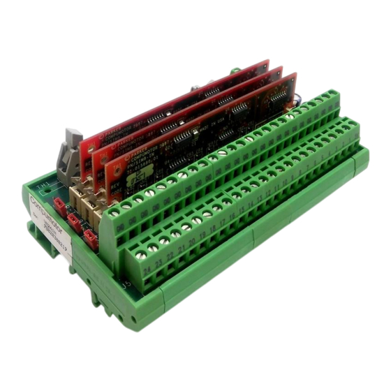
Board Type Color SIM8-IN SIM8-OUT Blue SIM8-4X4 Green P/N: SIM8-OUT PARKER COMPUMOTOR Fig. 1: Typical I/O Board Installing the VM24 Artisan Technology Group - Quality Instrumentation ... Guaranteed | (888) 88-SOURCE | www.artisantg.com... -
Page 13: I/O Pin Out Table
I/O Pin Out Table Screw Terminal VM24IN VM24OUT VM24S VM16/8 VM8/16 Number IN #1 OUT #1 IN #1 OUT #1 IN #1 IN #2 OUT #2 IN #2 OUT #2 IN #2 IN #3 OUT #3 IN #3 OUT #3 IN #3 IN #4 OUT #4... -
Page 14: Electrical Connections
Electrical Connections Fig. 2: Top View of the VM24 (shown without boards inserted) J1 ..SIM socket for I/O board 1, screw terminals 1-8. J2 ..SIM socket for I/O board 2, screw terminals 9-16. J3 ..SIM socket for I/O board 3, screw terminals 17-24. J4 .. - Page 15 J1 J2 J3 JU1 JU2 Fig. 3: Left-Side View of the VM24 (shown with boards inserted) Jumper for SIM slot J1. Jumper for SIM slot J2 Jumper for SIM slot J3 See page 11 for the description of jumper configurations. J3 J2 J1 RIGHT SIDE Fig.
-
Page 16: Jumper Configuration
Jumper Configuration The jumpers are used to configure the inputs for the I/O boards as sinking or sourcing. Each socket has its own corresponding jumper, allowing each board with inputs to be independently configured for sinking or sourcing. Sinking Inputs: Position 3 (shown) Jumps pull-up to V (pin 3) -
Page 17: Ribbon Cable Connection
Ribbon Cable Connection Caution Remove power to the VM24 before attaching or removing the cable. The VM24 is shipped with a 2-foot ribbon cable, with mating connectors. Connectors are keyed to ensure that they are inserted into mating connectors correctly. Cable installation for the VM24S, VM24-IN, and VM24-OUT consists of simply inserting the connector from one end of the cable into the Programmable I/O connector of the 6000 Series Controller/Indexer, then inserting the connector at the other end of the cable into connector J4 of the... - Page 18 Connect to Connect to Input Connector Output Connector on 6000 Controller on 6000 Controller Red Stripe Connect to J4 Connector on VM16/8 Fig. 6: Split Cable for the VM16/8 Installing the VM24 Artisan Technology Group - Quality Instrumentation ... Guaranteed | (888) 88-SOURCE | www.artisantg.com...
- Page 19 Connect to Connect to Output Connector Input Connector on 6000 Controller on 6000 Controller Red Stripe Connect to J4 Connector on VM8/16 Fig. 7: Split Cable for the VM8/16 VM24 I/O Module Artisan Technology Group - Quality Instrumentation ... Guaranteed | (888) 88-SOURCE | www.artisantg.com...
-
Page 20: Input Connection
Input Connections Caution Remove power to the VM24 before making any connections. Sinking External Supply (up to 24VDC) – VM24 Electronic 6000 Series Device Controller IN-P JUMPER The output should (J6) 0 KΩ be able to sink at Ground least 3mA of current. Connection (J6) (J4) -
Page 21: Output Connection
Output Connections Caution Remove power to the VM24 before making any connections. Connect the output pull-up pin OUT-P of the 6000 Series unit to V o on the VM24 module to ensure the proper sequencing of output signals upon application of power to the VM24. The Output, Ground, and +5V connections between the 6000 Controller and the VM24 are made with the 50-pin ribbon cable to the J4 connector. -
Page 22: Vm24 Module Configuration Summary
VM24 Module Configuration Summary The VM24 is shipped with the SIM8 boards already installed. 1. Mount the VM24 module (standard DIN rail). 2. Set the jumpers to position 3 (default) for sinking inputs or to position 1 for sourcing inputs. (See page 11). 3. - Page 23 Artisan Technology Group - Quality Instrumentation ... Guaranteed | (888) 88-SOURCE | www.artisantg.com...
-
Page 24: Chapter 2. Troubleshooting
C H A P T E R T W O Troubleshooting Artisan Technology Group - Quality Instrumentation ... Guaranteed | (888) 88-SOURCE | www.artisantg.com... -
Page 25: Troubleshooting Basics
Basic Troubleshooting When your system does not function properly (or as you expect it to operate), the first thing that you must do is identify and isolate the problem. When you have accomplished this, you can effectively begin to resolve the problem. - Page 26 6000 Series Controller/Indexer First, verify that 6000 Series Controller/Indexer I/O is functioning properly to aid in isolating the problem. Disconnect the 50-pin ribbon cable, or just disconnect the cable from connector J4 of the VM24, before performing this test. Outputs: Use the Transfer Output Status ( ) command to check the status TOUT...
- Page 27 50-pin Ribbon Cable Next, verify that the ribbon cable is relaying the signals properly. Connect the 50-pin ribbon cable to the 6000 Series unit, but do not connect the other end of the cable to the VM24. Repeat the above test, applying and checking voltages at the connector that would plug into J4.
-
Page 28: Sim Board Installation And Removal
Outputs Use the Transfer Output Status ( ) command to check the status TOUT of the outputs. Use the Output State ( ) command to change the outputs. Use a voltage meter to check individual outputs at the screw terminals (J4) of the VM24 to verify that the voltage level toggles between Ground and (V o -2). - Page 29 P/N: SIM8-OUT PARKER COMPUMOTOR Notch Fig. 9: I/O Board and Socket To Insert I/O Boards 1. Insert the I/O board into the socket, as shown in Fig. 9 above, and in Fig. 10 below. Start the I/O board at an angle of approximately 30°.
- Page 30 To Remove I/O Boards 1. Gently depress or push the metal socket clamps (see Fig. 11 below) to release the I/O board from the socket. 2. Tilt the I/O board toward the back of the socket and lift it out gently. Never force the I/O board out of the socket without releasing the clamps.
- Page 31 VM24 I/O Module Pin Out Table Screw Terminal VM24IN VM24OUT VM24S VM16/8 VM8/16 Number IN #1 OUT #1 IN #1 OUT #1 IN #1 IN #2 OUT #2 IN #2 OUT #2 IN #2 IN #3 OUT #3 IN #3 OUT #3 IN #3 IN #4...
Need help?
Do you have a question about the VM24 Series and is the answer not in the manual?
Questions and answers