Table of Contents
Advertisement
Quick Links
No. CP-SP-1049E
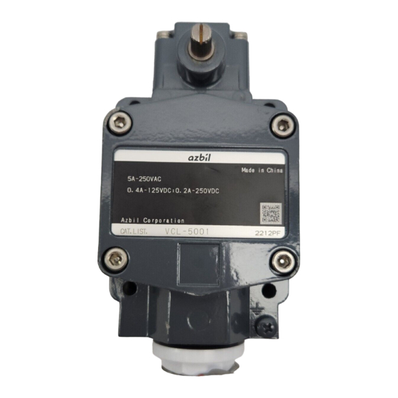
Enclosed Limit Switch
VCL-5✽✽✽-✽✽ Series
User's Manual
Thank you for purchasing our product.
This manual contains information for
ensuring correct and safe use of this
product.
Please read and understand it thor-
oughly before using this product,
and keep it nearby after installation for
handy reference.
Advertisement
Table of Contents

Subscribe to Our Youtube Channel
Related Manuals for Azbil VCL-5 Series


Summary of Contents for Azbil VCL-5 Series
- Page 1 No. CP-SP-1049E Enclosed Limit Switch VCL-5✽✽✽-✽✽ Series User's Manual Thank you for purchasing our product. This manual contains information for ensuring correct and safe use of this product. Please read and understand it thor- oughly before using this product, and keep it nearby after installation for handy reference.
- Page 2 If you should find an error or omis- sion, please contact the azbil Group. In no event is Azbil Corporation liable to anyone for any indirect, special or consequential damages as a result of using this product.
- Page 3 SAFETY PRECAUTIONS ■ About Icons The safety precautions described in this manual are indicated by various icons. Please be sure you read and understand the icons and their meanings described below before reading the rest of the manual. Safety precautions are intended to ensure the safe and correct use of this prod- uct, to prevent injury to the operator and others, and to prevent damage to proper- ty.
- Page 4 WARNING Be sure to turn the power supply of the equipment OFF before wiring the limit switch. Failure to do so might result in electric shock depending on power supply voltage or involved in unsafe condition such as unintentional machine start. Never use or leave the limit switch unattended with the cover or conduit open.
-
Page 5: Table Of Contents
Contents Safety Precautions Conventions Used in This Manual Chapter 1. OUTLINE ■ Features ・ ・ ・・・・・・・・・・・・・・・・・・・・・・・・・・・・・・・・・・・・・・ ■ Specifications ・・・・・・・・・・・・・・・・・・・・・・・・・・・・・・・・・・・・ Chapter 2. NOMENCLATURE ■ Appearance and Structure of the Limit Switch ・・・・・・・・・・・・・・・・ ■ Model Number Construction ・・・・・・・・・・・・・・・・・・・・・・・・・・・ Chapter 3. INSTALLATION ■ Installation ・・・・・・・・・・・・・・・・・・・・・・・・・・・・・・・・・・・・・・... - Page 6 Conventions Used in This Manual The following conventions are used in this manual: Handling Precautions : Handling Precautions indicate items that the user should pay attention to when handling the limit switch. (1), (2), (3) : The numbers with the parenthesis indicate steps in a sequence or indicate corresponding parts in an explanation.
-
Page 7: Chapter 1. Outline
Max. operating humidity 98%RH The detailed specifications for the limit switch are described in the product specification sheet. The product specification drawing Nos. are shown below. These drawings can be obtained from your Azbil Corporation representative. Product specification drawing No.:AD50424E... -
Page 8: Chapter 2. Nomenclature
Chapter 2 NOMENCLATURE ■ Appearance and Structure of the Limit Switch The force applied from outside the limit switch is transferred to the actuator lever →shaft → plunger → internal switches, to switch the electrical circuit. The limit switch lever rotates both cw and ccw. Lever mounting screw Shaft Roller... -
Page 9: Chapter 3. Installation
Chapter 3 INSTALLATION This chapter describes the installation procedure for the limit switch. WARNING This switch is not explosion-proof. If an explosion-proof specification is required, use the VCX-5 ✽✽✽ series. CAUTION Until wiring, do not remove the cover and the plug of the limit switch in order to prevent dust or liquid from entering the limit switch. -
Page 10: Installation
Chapter 3 INSTALLATION ■ Installation ● Installation The plate on which the limit switch is mounted must be sufficiently rigid, be made of an appropriate material in an appropriate shape and be thick enough to retain its shape by the operating force of the limit switch. When mounting the limit switch, use washers to prevent the screws from working loose. - Page 11 Chapter 3 INSTALLATION ● Dog surface finish When designing the dog, its surface finish(roughness and hardness) shall be as follows: Suitable value Surface Roughness 1.6a(6.3s) Vickers hardness Hv450 By applying grease to dog surface, smoother action of roller can be attained. Handling Precautions Dog shall not touch any portion other than the roller.
-
Page 12: Changing The Lever Direction
Chapter 3 INSTALLATION ■ Changing the Lever Direction ● Procedure (1) Loosen the lever mounting screw. (2) Turn over the lever and insert lever securely in the new position. (3) Fasten the lever mounting screw according to the tightening torque shown in the table below. -
Page 13: Chapter 4. Wiring
Chapter 4 WIRING This chapter describes the wiring of the limit switch. WARNING Be sure to turn the power supply of the equipment OFF before wiring the limit switch. Failure to do so might result in electric shock due to high power supply voltage. - Page 14 Chapter 4 WIRING ● Wiring CAUTION Correctly wire the limit switch referring to the circuit drawing on the inside of the cover or the Product Specification Sheet. • The terminal screw must be fastened according to the tightening torque shown in the table below.
-
Page 15: Adjustment Procedure
Chapter 5 ADJUSTMENT PROCEDURE ■ Items to be Checked before Operation Check the following items before operating the limit switch: (1) Wiring must be completed correctly. (2) Mounting screws, lever mounting screw, and cover mounting screws must be fastened tightly. (3) Seal connector or flexible piping must be used for the conduit to ensure the appropriate sealing performance. -
Page 16: Chapter 6. Maintenance & Inspection
Chapter 6 MAINTENANCE & INSPECTION CAUTION After inspecting the limit switch, firmly tighten the cover and conduit. Insufficient tightening for some reason such as corroded threads will degrade sealing performance, which can cause problems such as breakdown of insulation, leading to the unsatisfactory functioning of this limit switch. Periodically inspect the limit switch to ensure safe use. - Page 17 Revision History Printed Manual Number Edition Revised pages Description Date 99-01 CP-SP-1049E 1st Edition 03-09 2nd Edition Fonts changed. RESTRICTIONS ON USE changed. ●Movement and force after operation was moved to 5 pages. A part of expression was changed. The 2nd item of "CAUTIONS" was deleted. The 3rd item of "Handling Precautions"...
- Page 18 Azbil Corporation's products. 2. Ascertainment of suitability You are required to ascertain the suitability of Azbil Corporation's products in case of your use of the same with your machinery, equipment, etc. (hereinafter referred to as "Equipment") on your own responsibility, taking the following matters into consideration: (1) Regulations and standards or laws that your Equipment is to comply with.
- Page 19 Although acceleration of the above situation varies depending on the conditions or environment of use of the products, you are required not to use any Azbil Corporation's products for a period exceeding ten (10) years unless otherwise stated in specifications or instruction manuals.
- Page 20 Specifications are subject to change without notice. (09) 1-12-2 Kawana, Fujisawa Kanagawa 251-8522 Japan URL: http://www.azbil.com 1st edition: Jan. 1999 (M) 4th edition: Apr. 2012 (M)
Need help?
Do you have a question about the VCL-5 Series and is the answer not in the manual?
Questions and answers