
Related Manuals for Dynon Avionics EFIS-D10A


Summary of Contents for Dynon Avionics EFIS-D10A
- Page 1 EFIS-D10A Installation Guide This product is intended for the experimental aircraft category and is not approved for installation in certified aircraft Revision D 10/4/2006 Copyright © 2006 by Dynon Avionics...
-
Page 3: Contact Information
Contact Information Dynon Avionics, Inc. Woodinville, WA 98072 (425) 402-0433 www.dynonavionics.com Copyright © 2006 Dynon Avionics. All rights reserved. No part of this manual may be reproduced, copied, transmitted, disseminated or stored in any storage medium, for any purpose without the express written permission of Dynon Avionics. -
Page 5: Table Of Contents
Setting Zero Pitch (In flight)............................4-1 Compass Heading Calibration ........................... 4-1 Setting Magnetic Inclination Angle (Required)....................4-1 EFIS-D10A (Internal) Heading Calibration (on ground and in flight) .............. 4-2 EDC-D10A Heading Calibration (on ground only)................... 4-4 Configure Airspeed Color Thresholds........................4-6 5. - Page 6 Electrical Installation............................5-13 Recommended wiring practices........................5-13 Step 1: Transponder Wiring..........................5-13 Step 2: Connecting to the EFIS-D10A ......................5-14 Step 3: EFIS-D10A Encoder Format ........................5-15 Appendix E: Replacing the EFIS-D10A battery pack ....................5-16 Appendix F: Weights..............................5-16 Appendix G: EFIS-D10A Specifications........................5-17 EFIS-D10A Installation Guide...
-
Page 7: Introduction
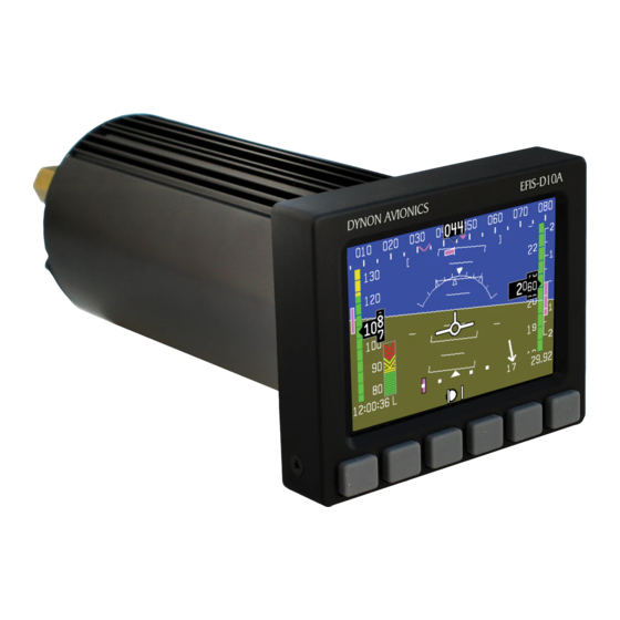
EFIS-D10A Pilot’s User Guide. Description The EFIS-D10A uses solid-state sensor technology to give an accurate and easy-to-understand display. To ensure accuracy in its readings, it is very important that you install the instrument correctly and perform the specified calibration steps. This installation guide will help you through that process. -
Page 9: Wiring
Power is fed to the EFIS-D10A via pins in the female DB25 connector as shown on the 25-Pin Female EFIS Harness diagram on page 2-2 The EFIS-D10A system-wide power requirement is 8 watts typical and 13 watts maximum. -
Page 10: 25-Pin Female Efis Harness
Wiring 25-Pin Female EFIS Harness Below is the wiring diagram of the EFIS 25-pin female harness. If you purchased your harness from Dynon Avionics, it is color coded according to the chart on the following page. EFIS-D10A Installation Guide... - Page 11 DSAB-B Page 3-9 No Connect No Connect No Connect White (bundled) PC Serial Ground Page 3-4 EFIS-D10A Transmit / PC Serial Page 3-4 White (bundled) Receive (RS-232) White/Orange (Red on some Page 3-1 EDC-D10A Data B harnesses) White/Blue (Black on some...
-
Page 12: Wiring System Overview
The following block diagram depicts the basic layout of the EFIS electrical connections and is for reference only. Read the specific instructions for each connection prior to installation. The colors shown refer to the Dynon-supplied EFIS harness. EFIS-D10A Installation Guide... -
Page 13: Instrument Installation
The bracket used to hold the EDC-D10A must hold the EDC-D10A at the same pitch, roll, and yaw as the EFIS-D10A with respect to the airframe. We recommend you use an electronic level that reads to 1/10 of... -
Page 14: Edc-D10A Communication Cable
Instrument Installation a degree to make sure the EDC-D10A is aligned with the EFIS-D10A to better than 1 degree. • All mounting hardware needs to be made from non-ferrous material such as aluminum, plastic, or brass. Many stainless steel screws are magnetic. If the item is attracted to a magnet, it should not be used in the installation. -
Page 15: Power Inputs
Instrument Installation should see no change in the displayed heading when the headset earpiece and its magnetic speaker is near the EFIS-D10A. If you see a substantial change in heading, there is a communication problem between the EFIS-D10A and the EDC-D10A. -
Page 16: Serial Communication Cable
Ensure that the adapter driver CD is inserted in your PC before plugging the adapter into the USB port for the first time. Also, do not have your EFIS-D10A plugged into the USB-to-Serial while installing the driver. -
Page 17: Sl30 And/Or Gps Connection
EFIS-D10A (e.g., pin 9 on the DB25). When a Dynon product is connected to a GPS, it will synchronize its Zulu clock to the time output by the GPS. -
Page 18: If You Own Only A Flightdek-D180
(GND and Encoder Transmit) from the DB25 connector to their respective connections on your transponder. Per ATC/FAA requirements, the serial encoder output of the EFIS-D10A reports pressure altitude, which, by definition, is indicated altitude when the baro is set to 29.92. So, when you set your EFIS-D10A's baro adjustment to 29.92, its indicated... -
Page 19: Serial Altitude Formats
ALT 05200[CR] Example message Format 4 Trimble, Garmin GTX327 (set on Icarus input), Garmin Used By GTX330 (set on Icarus input), Icarus 9600 Baud rate ALT, space, five altitude bytes, carriage return Format ALT 05200[CR] Example message EFIS-D10A Installation Guide... -
Page 20: Audio Alert Output
Outside terminal To ground To set the volume of the AOA alarm, you will need your EFIS-D10A powered on and the alarm output wired as described above. Enter the EFIS menu by pressing any button (except the leftmost or rightmost) beneath an EFIS page. Press MORE > SETUP > MORE > MORE >... -
Page 21: Dynon Smart Avionics Bus (Dsab) Wiring
Function color communication will allow features such as data sharing and DSAB-A Green alarm notification between units. The EFIS-D10A, EMS-D10, DSAB-B Blue EFIS-D100, EMS-D120, and FlightDEK-D180 products all have the hardware to support DSAB connections; currently the only supported function is transmitting data from an EMS product to an EFIS product. Once you connect your EFIS product and EMS product via the DSAB lines, you will have access to EMS pages on your EFIS. -
Page 22: Panel Location And Mounting
10A into your panel: standard or flush. You may use the optional flush-mount bracket, allowing the face of the EFIS-D10A to be flush with your panel. If you opted to receive the flush mount bracket, please skip to Option 2 below. If you... -
Page 23: Option 2: Flush-Mount Bracket
EFIS-D10A into place in the panel, putting the washers in between the EFIS-D10A and the panel. Place one of the 4 supplied mounting nuts on the end of each of the 4 studs protruding from the back of the panel. Secure the nuts tightly against the panel to complete the installation. -
Page 24: Connecting Static & Pitot Lines
If you purchased Dynon’s AOA pitot tube, note that it has pitot and AOA ports on it, but not static. You will need to provide your own source of static pressure for the EFIS-D10A and any other instrument in your panel which requires it. -
Page 25: Efis Calibration And Configuration
This section will take you through a series of steps to make sure that you have properly installed and configured your EFIS-D10A. As in the User’s Guide, the term, “button #1” refers to the leftmost button on the front panel of the EFIS-D10A, “button #2,” the next button to the right, and so on. - Page 27 EFIS Calibration and Configuration During magnetic calibration, do not turn the power off on the EFIS-D10A. This will cause any recorded compass calibration data to be lost; the calibration will need to be restarted. 1. Enter the EFIS calibration menu by pressing any button beneath an EFIS page (except the far left or far right hotkeys), then MORE >...
-
Page 28: Edc-D10A Heading Calibration (On Ground Only)
Avionics EDC-D10A Remote Compass. You wi ll need to repeat this process anytime you move the EFIS-D10A to a new location in yo plane o r change the magnetic or elec trical characteristics of the nearby environment (i.e. - Page 29 EFIS Calibration and Configuration 1. Turn on the EFIS-D10A and allow it to warm up for at least 15 minutes before performing the calibration. 2. Align the airplane pointing magnetic North as closely as possible. On the EFIS-D10A, enter the menu system by pressing any button beneath an EFIS page (except the far left or far right hotkeys) and press MORE >...
-
Page 30: Configure Airspeed Color Thresholds
When you have completed all 5 settings, you have completed the airspeed color thresholds onfiguration. Note that you will not be able to see some of the colors until the aircraft has ieved airspeeds in the range of each threshold. EFIS-D10A Installation Guide... -
Page 31: Appendix
Avionics to return for service. INTERNAL BATTERY CHECK If your EFIS-D10A has a rechargeable internal emergency battery, it is necessary to ensure that the batte ry capacity is such that it will last at least 2 hours on a full charge. At least once per year, perform the following test. -
Page 32: Firmware Upgrade
MORE > DIM and increase the brightness until it will not increase anymore. 4. Let the unit remain on for 2 hours. 5. If, after these 2 hours, your EFIS-D10A has not turned off and does not display the INTERNAL BATTERY LOW warning, your battery passes the capacity test. - Page 33 EDC-D10A is failed been disconne cted. If you have an wiring or connectors. Examine the OAT connecte d to your EDC- wiring run between the EFIS-D10A D10A, you will lose this reading, and EDC-D10A for possible as well. problems. EFIS-D10A Installation Guide...
- Page 34 Appendix TROU BLESHOOTING GUIDE The fol lowing table provides a list of potential issues that the EFIS-D10A may experience. ptom is given on the left side while the probable solution is listed at the right. Problem Solution After p erforming a magnetic...
-
Page 35: Instructions For Return
EFIS-D1 0A to us. If your unit is still under warranty, the repairs will be performed and the EFIS-D10A will be returned promptly. If your warranty has expire , the Dynon representative will m... -
Page 36: Appendix B: Dynon Oat Probe Installation And Usage
OAT or TAS/Density Altitude system. If you own an Dynon E MS product with an OAT ins talled, your EFIS-D10A can receive its OAT value from the EMS via the DSAB wires. See the Dynon Smart Avionics Bus (DSAB) Wiring section on page 3-9 for information on connectin g the two instruments. -
Page 37: Oat/Tas/Da Display
To connect the blue wire, white wire, and shield (the three ground connections) into one pin, crimp a connector onto the stripped end of the ground wires from the EFIS-D10A (or, if using the Dynon-supplied harness, use the existing pinned ground lead). Strip some extra insulation off this ground wire. -
Page 38: Calibration And Adjustment
Ensure that you have selected the number corresponding to your OAT in the OAT INSTALLED enu as described a bove. It can sometimes take as long as 5 seconds for the EFIS-D10A to lock onto the OAT reading. Ensure that all wiring is correct and that there are no shorted or open connections. -
Page 39: Appendix C: Dynon Aoa/Pitot Installation And Calibration Guide
Gretz Aero pitot mounting kit for the PH502-12CR or AN5812 pitot, available at http://aircraftspruce.com http://www.gretzaero.com http://www.safeair1.com) that will allow you to mount the Dynon Avionics AOA/Pitot probe to your airplane. Examples of the mount installation could be found at: http://bmnel lis.com/WingSkinning3.htm http://www.cafes.net/ leo/RV-6/Pitot/Pitot.html EFIS-D10A Installation Guide... -
Page 40: Dimensions
Appendix DIMENSIONS Standard mount Boom mount 5-10 EFIS-D10A Installation Guide... -
Page 41: Installation
CAUTION: It is your responsibility to fly your plane safely while performing any configuration or calibration in flight. The best scenario would include a second person to perform any necessary steps on the EFIS-D10A. Once you are flying straight and level at a safe altitude for stalls, 1. -
Page 42: Alarm Setup
FINISH. At this point, the angle-of-attack has been calibrated. If it is not visible, make it visible through the menu system (see “Show/hide display items” in EFIS-D10A Pilot’s User Guide). This calibration should result in the lowest angle-of-attack stall occurring just above the red/yellow boundary. -
Page 43: Appendix D: Encoder Serial-To-Gray Code Converter Installation
EFIS-D10A and outputs standard Mode-C parallel Gray code into your Mode-C transponder. This Encoder Converter requires data from the EFIS-D10A and is not to be confused with other standalone encoders available on the market. While the installation is not complex, it is important that you install the unit correctly. -
Page 44: Step 2: Connecting To The Efis-D10A
(or red) and black respectively, and 2 feet in length. Connect these wires to the EFIS-D10A 25-pin female harness. Ensure that your EFIS-D10A is powered off. Then connect the black EFIS Ground wire to pin 21. Then, connect the green wire to pin 13 (Serial Encoder Transmit) on the EFIS harness. -
Page 45: Step 3: Efis-D10A Encoder Format
Black Serial Encoder Ground STEP 3: EFIS-D10A ENCODER FORMAT For proper communication the EFIS Altitude Encoder format must be set to format number o To change this setting, from the main menu, select: MORE > SETUP > MORE > ALTENC. -
Page 46: Appendix E: Replacing The Efis-D10A Battery Pack
Appendix Appendix E: Replacing the EFIS-D10A battery pack • Remove the three 7/64” hex screws (screw 1,2,3) from the battery door of the EFIS-D10A shown below (do not remove the Phillips or D-sub screws). Screw Screw Screw • (If previously had a battery) Disconnect the battery from... -
Page 47: Appendix G: Efis-D10A Specifications
EFIS-D 10A: 1 lb 9 oz. (709 g) echanical EFIS-D10A + battery: 1 lb 15 oz. (879 g) EDC-D10A: 3.6 oz. (102 g) Operating -22° to 122° F (-30° to 50° C) Temperature Voltage: 10 - 30 Vdc...
Need help?
Do you have a question about the EFIS-D10A and is the answer not in the manual?
Questions and answers