
Related Manuals for Dynon Avionics FlightDEK-D180


Summary of Contents for Dynon Avionics FlightDEK-D180
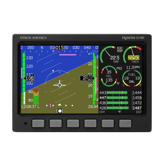
- Page 1 FlightDEK-D180 Combined EFIS and EMS Pilot’s User Guide P/N 100601-000, Revision F For use with firmware version 5.1 May, 2009 Dynon Avionics This product is not approved for installation in type certificated aircraft...
-
Page 2: Copyright
Copyright © 2003-2009 Dynon Avionics, Inc. All rights reserved. No part of this manual may be reproduced, copied, transmitted, disseminated or stored in any storage medium, for any purpose without the express written permission of Dynon Avionics. Dynon Avionics hereby grants permission to download a... -
Page 3: Limited Warranty
MAY NOT APPLY TO YOU. Dynon Avionics retains the exclusive right to repair or replace the instrument or firmware or offer a full refund of the purchase price at its sole discretion. SUCH REMEDY SHALL BE YOUR SOLE AND EXCLUSIVE REMEDY FOR ANY BREACH OF WARRANTY. -
Page 5: Table Of Contents
About this Guide................................1-2 2. Product Overview FlightDEK-D180 Hardware...............................2-1 ADAHRS Operation................................2-4 3. Product Operation Front Panel Layout ................................3-1 Display....................................3-2 Menus ....................................3-6 4. Available Pages EFIS Main pages ................................4-2 HSI Page....................................4-9 EMS Main Pages ................................4-10 EMS Auxiliary Page................................4-11 FlightDEK-D180 Pilot’s User Guide... - Page 6 Accessing the HSI/DG Page ............................. 6-1 HSI Display Basics ................................6-2 Navigation Radio Overlay ..............................6-4 GPS Overlay ..................................6-7 HSI Menu Structure................................6-9 7. Autopilot Operation Introduction and Resources .............................. 7-1 EFIS AP Indicators ................................7-2 FlightDEK-D180 Pilot’s User Guide...
- Page 7 9. EMS Monitoring Functions Engine Leaning and Power..............................9-1 Detonation Characterization ..............................9-2 Pre-ignition Characteristics ...............................9-3 Ignition Misfire..................................9-3 Shock Cooling ...................................9-3 Data Logging ..................................9-3 10. EMS Operation 10-1 ON/OFF...................................10-1 Display Brightness (DIM) ...............................10-1 Fuel Computer .................................10-2 Engine Leaning................................10-3 Clock Setup ..................................10-3 FlightDEK-D180 Pilot’s User Guide...
- Page 8 Table of Contents Timers....................................10-4 Global Configuration Settings ............................10-5 11. Appendix 11-1 Appendix A: Serial Data Output............................11-1 Appendix B: PC Support Program...........................11-6 Appendix C: Troubleshooting ............................11-6 Appendix D: FlightDEK-D180 Specifications ......................11-11 viii FlightDEK-D180 Pilot’s User Guide...
-
Page 9: Introduction
OEM Installations If your FlightDEK-D180 is installed by an OEM distributor, you may find that you are unable to access some menus and settings. Some Dynon distributors customize various areas of the FlightDEK-D180 firmware to maintain a consistent pilot experience and minimize integration issues across a large number of installations. -
Page 10: Warning
About this Guide This guide serves two purposes. The first is to help you configure and get acquainted with the FlightDEK-D180‘s many functions. The second is to give you quick access to vital information. For detailed technical and installation information, please refer to the FlightDEK-D180 Installation Guide. - Page 11 Any text following this icon describes functionality available only with the AP74 Autopilot Interface Module connected to your system. Any text following this icon describes functionality that is possible when multiple Dynon Avionics products are networked together via the Dynon Smart Avionics Bus (DSAB).
-
Page 13: Product Overview
2. PRODUCT OVERVIEW This section provides a general overview of the various parts of the FlightDEK-D180 as well as a theory of operation. The information in this section serves as a reference only and helps familiarize you with the inner workings of the unit. It should not be used for diagnostic or reparative work. - Page 14 Note that the failure of a unit in a DSAB network may cause the loss of some or all data shared between units. In the above example, if the connected EMS/FlightDEK-D180 were to fail, the EFIS would no longer be able to behave as an engine monitor.
- Page 15 Hold, GPS horizontal navigation, altitude hold), and allow you to engage and disengage the Autopilot. When an HS34 is configured to control the FlightDEK-D180, its VALUE knob changes values when in various EFIS menus. When no menus are displayed the HS34 can adjust the barometer or altitude bug. The HS34’s HEADING and COURSE knobs affect their respective parameters on the HSI page.
-
Page 16: Adahrs Operation
ATTITUDE CALCULATION The FlightDEK-D180 artificial horizon display (attitude) is generated via a complex algorithm using a multitude of sensors. Your EFIS attitude is not reliant on any single external system. It can provide an accurate attitude - even in the event of airspeed loss (due to icing or other blockage) - via a redundant GPS aiding source. - Page 17 COMPASS ACCURACY AND AUTOPILOT PERFORMANCE If you are using your FlightDEK-D180 to control Dynon’s Autopilot, it is critical that the magnetic heading be as accurate as possible for comfortable operation in HDG mode and the upcoming radio-based VOR/NAV mode. The aircraft’s compass must be installed correctly, calibrated, and operating well in all attitudes.
-
Page 19: Product Operation
3. PRODUCT OPERATION After reading this section, you will be familiar with the basics of how to use your FlightDEK-D180. For details regarding specific procedures (e.g., adjusting display brightness, using the fuel computer, setting the clock, etc.) please refer to the EFIS Operation and EMS Operation sections. -
Page 20: Display
Product Operation Display The FlightDEK-D180 display is the most obvious and commonly used output of the device. It is capable of displaying EFIS, HSI, and/or engine data simultaneously. SCREENS AND PAGES The terms in the following bulleted list are used in this section and are defined as follows: •... - Page 21 The SCREEN LIST Menu uses icons to illustrate the layout for each screen configuration. EFIS/EMS (default FlightDEK-D180 boot-up screen; in default rotation) EFIS/AUX (in default screen rotation) EFIS/FUEL (in default screen rotation) EFIS/TIMES (in default screen rotation)
- Page 22 If you which you may switch to, and set up, various screen configurations. wish to access screens that are not in your rotation, use the SCREEN LIST as described above. FlightDEK-D180 Pilot’s User Guide...
- Page 23 Press SETUP, then press ORDER to display the menu used to change the screen order. Scroll through the pre-defined screens using the DOWN▼/UP▲ buttons. Press the MV DN▼ FlightDEK-D180 Pilot’s User Guide...
-
Page 24: Menus
Likewise, press the MV UP▲ button to move the selected screen up in the screen list. Menus All interaction with the FlightDEK-D180 is accomplished through the use of its menu system. The menu system is accessed and navigated via the six buttons located on the front of the unit. - Page 25 MENU►. Pressing the button switches the menu to display the right page’s menu, and the label switches to read ◄MENU. The arrow on this button always points to the side of the screen whose menu is displayed when pressing the button. FlightDEK-D180 Pilot’s User Guide...
- Page 26 “EFIS > INFO > LEFT” indicates entering the EFIS menu, pressing MORE, then pressing INFO, and then pressing LEFT to enter the left info item menu. Note that the MORE button is not included in the sequence, since pressing MORE reveals more options in the same level of the menu system. FlightDEK-D180 Pilot’s User Guide...
-
Page 27: Available Pages
DG style compass by itself or overlaid with lines and arrows of different colors. Note: HSI pages use data that is obtained from a source external to the FlightDEK-D180. Refer to the FlightDEK- D180 Installation Guide for a list of compatible equipment. -
Page 28: Efis Main Pages
Available Pages EFIS Main pages Available in 1/3, 2/3 and full formats The FlightDEK-D180 default screen rotation includes only 2/3 EFIS pages combined with the various EMS and HSI pages described below. However, you may also choose screen configurations that use 1/3 and full-screen pages. The 2/3 and full-screen pages can display EFIS- and EMS-related info items on the left and right side of the screen. - Page 29 Unlike a mechanical artificial horizon, the FlightDEK-D180‘s horizon has no roll or pitch limitation. The horizon line stays parallel to the Earth’s horizon line regardless of attitude. The parallel lines above and below the horizon line are the pitch indicator lines, with each line indicating 5 degrees of pitch.
- Page 30 Like a conventional gyro-stabilized magnetic compass, magnetic heading reacts immediately to turn rate so that heading changes are reflected immediately. It then uses magnetometer data over the long term to ensure that it remains correct. Additionally, heading is corrected for attitude so that it is accurate as you pitch and roll. FlightDEK-D180 Pilot’s User Guide...
- Page 31 The FlightDEK-D180 accurately displays altitudes from -1200 to 30,000 ft (-365 to 9144 m). The graphical Vertical Speed Indicator is located next to the altitude tape. The magenta ba r grows in the direction of –...
- Page 32 Located in the lower right corner of the EFIS page, the elevator trim indicator displays the relative trim of the elevator in graphic form. The elevator trim indicator can only be displayed on the FlightDEK-D180 if an elevator trim sensor is properly connected to one of the 3 EMS GP inputs, and is properly configured in the EMS setup.
- Page 33 AOA changes with configuration. Because of this, a stall could occur anywhere inside the yellow range, but will occur at the same point every time given a specific configuration. Refer to the FlightDEK-D180 Installation Guide fo more information on calibrating the AOA indicato Airspeed tape, digital readout, and trend The airspeed tape scrolls beneath the airspeed digital readout and arrow.
- Page 34 Local time (L), Zulu time (Z), or a timer (T). If a GPS is connected to your Dynon network and is outputting time information, the Zulu time of all connected products is auto-set to that reported by the GPS. FlightDEK-D180 Pilot’s User Guide...
-
Page 35: Hsi Page
HSI Page Available in 1/3 format Your FlightDEK-D180 can function as a Horizontal Situation Indicator (HSI) when it is receiving data from Dynon’s HS34 (connected to a NAV radio), an external GPS, or Garmin SL30 Nav radio. The HSI information is overlaid on a directional gyro (DG) representation of the EFIS’s stabilized magnetic heading information. -
Page 36: Ems Main Pages
CHTs are displayed using their own set of green bars on a different scale than EGTs with their respective numeric values displayed to the right of each bar. When displayed as a 1/3 page, with the exception of two cylinder engines, the EGT/CHT display is shown in combined mode. 4-10 FlightDEK-D180 Pilot’s User Guide... -
Page 37: Ems Auxiliary Page
The commands are listed below. Info item quick commands • TIMERS info item – TRPRST (resets the trip timer), TIMER (shortcut to the general purpose timer menu) • FUEL – FUEL (shortcut to the add fuel menu) FlightDEK-D180 Pilot’s User Guide 4-11... -
Page 38: Ems Times Page
• The Flight Timer shows the total amount of time that oil pressure is above 15 PSI since the FlightDEK-D180 was turned on; it does not reset until the next time the FlightDEK-D180 is power-cycled and oil pressure reaches 15 PSI. The Trip Timer shows cumulative flight time since a manual reset. -
Page 39: Ems Fuel Computer Page
This allows you to view the fuel used value from your last flight. Some user input is required for the FlightDEK-D180 Fuel Computer to function properly. Refer to the EMS Operation section on page 10-2 for instructions on adjusting various Fuel Computer parameters. -
Page 40: Lists Pages
Press SEL► to expand the menu into another list of options to the right. Any line on a Menu Page that is not followed by ► indicates that its value can be modified using the SEL►, DOWN▼, and UP▲ buttons. 4-14 FlightDEK-D180 Pilot’s User Guide... -
Page 41: Efis Operation
POWER – Power on/off When the FlightDEK-D180 is turned off but still has a power source via one of the three power inputs, press the far left button to turn the unit on. Likewise, once the unit is on and no menus are displayed, push and hold the leftmost button to turn it off. -
Page 42: Bugs - Setting Bug Markers
In the HDG bug menu the value-setting box is displayed in the lower part of the display. Press SEL► to select which digit to change and DEC- and INC+ to change the selected digit. Press the SYNC button to synchronize the heading bug FlightDEK-D180 Pilot’s User Guide... - Page 43 If you have the airspeed bug displayed, the marker moves up or down the airspeed tape as you change its value. The airspeed bug can be adjusted on any EFIS page in the system and is synchronized across all EFIS-based units. FlightDEK-D180 Pilot’s User Guide...
- Page 44 150 feet of the target. Flying more than 200 feet away from the target triggers a short audio alert and alternates the bug in red and yellow as a visual alert. When below the 200-foot window, a rising tone is sounded; when above the 200-foot FlightDEK-D180 Pilot’s User Guide...
-
Page 45: Lists - Using Checklists And Data Panels
The Dynon Support Program allows you to enter your own checklists or select from included data panels. These checklists and data panels can then be uploaded to your FlightDEK-D180 for quick access from the main menu or from your screen rotation. Data panels and checklists can be included beneath 5 user-configurable categories and each category can contain up to 5 checklists or data panels. -
Page 46: Setup - Setting Preferences
Enter the EFIS > SETUP menu to make changes to preferences. Many of the settings in this menu should only be changed by the installer, and are described in the FlightDEK-D180 Installation Gu ide. The preferences and settings that are relevant to the pilot and in-flight operation are explained below. - Page 47 (and, if necessary for the time zone, the half-hour offset) for the local time. Be aware that connecting to the FlightDEK-D180 with the Dynon Product Support Program resets the time; do not set the time until you have performed all of the PC interface operations.
- Page 48 Toggles the display of the current altimeter setting (also known as the Kollsman setting). This display is not required to set the altimeter setting. While in the EFIS > BARO menu, a separate value-setting box appears, allowing adjustments to be made. FlightDEK-D180 Pilot’s User Guide...
- Page 49 Toggles the display of the ground track indicator on the heading tape. The track indicator is a magenta arrow and is only displayed when the FlightDEK-D180 is receiving valid GPS data from an external source. If the GTRK button status displays “Y”...
-
Page 50: Info - Informational Items
The EFIS > SETUP > VRSION menu gives you two important pieces of information: your FlightDEK-D180‘s current firmware version; and the number of hours the FlightDEK-D180 has been on. If you require technical support or other assistance from Dynon, please have your firmware version ready when you call or write. - Page 51 FlightDEK-D180 internal battery voltage. If any of the 3 voltage inputs are not present, 00.0V is displayed for the respective voltage values. The letter V follows all three values, denoting the fact that voltages are being displayed. The FlightDEK-D180 alerts you when the internal battery is low by displaying a low battery alert.
- Page 52 When multiple units are connected to a DSAB network, one primary OAT is shared between all units. This can be an OAT connected to an EFIS or an EMS. If the FlightDEK-D180 is displaying an OAT provided by another unit in the system, changing the OAT type or install status on the FlightDEK-D180 has no effect on the displayed OAT.
-
Page 53: Dim - Changing Screen Brightness
In the EFIS > DIM menu, press BRITR or DRKR to change the brightness of the display. It is not possible to turn the screen completely black. Note that if power to the FlightDEK-D180 is cycled, the screen is reset to full brightness. -
Page 54: Timer - Setting And Using A Timer
OATSET – Setting Temperature Offset If you did not purchase an EFIS or EMS outside air temperature sensor from Dynon Avionics, you may still manually adjust the OAT to an approximate value. With this manually entered information, the FlightDEK-D180 calculates and displays true airspeed (TAS) and density altitude as it does when an OAT is connected. - Page 55 In the EFIS > OATSET menu, press INC- or DEC+ until the value-setting box above the menu displays the current outside air temperature. This value is then used in the OAT/TAS/DA info item on the EFIS screen. For more information on setting up that display, see page 5-12. FlightDEK-D180 Pilot’s User Guide 5-15...
-
Page 57: Hsi Operation
30 Nav/Comm radio via a serial connection (Nav data), a Garmin GNS-430/530 GPS/Nav/Comm (GPS data), or any GPS that outputs in either NMEA-0183 or aviation format. Please refer to the FlightDEK-D180 Installation Guide for instructions on how to connect these devices to your Dynon network. Also, ensure your GPS device is configured to output magnetic heading since all calculations and displays are done in reference to the local magnetic heading. -
Page 58: Hsi Display Basics
VOR or localizer tuned. This is the same as a cross hatch indicator in the TO/FROM flag on a mechanical CDI. Do not rely on any indications on this page except for the DG and TAS when this flag is set. FlightDEK-D180 Pilot’s User Guide... - Page 59 The HEADING knob on the HS34 always controls the heading bug. Turning the knob when the bug is not displayed switches the bug to the on state. Press the HEADING knob to sync the bug to the current heading. FlightDEK-D180 Pilot’s User Guide...
-
Page 60: Navigation Radio Overlay
This setting is also shown in the text area as “OBS.” When tuned to a VOR, this is the radial that you wish to fly. When tuned to an ILS, this is set to the runway heading. In a situation with no winds, keeping the course indicator pointed straight FlightDEK-D180 Pilot’s User Guide... - Page 61 “from” indication. This data comes from the to/from flag indicator provided by your Nav radio. In the image above, the to/from indicator is showing a “from” indication. FlightDEK-D180 Pilot’s User Guide...
- Page 62 The HS34 adds the ability to display information from a marker beacon receiver. If you have marker beacon receiver connected and configured (as described in the FlightDEK-D180 Installation Guide), the “O,” “M,” and “I” indications are displayed on the HSI page. If configured, the HS34 plays the appropriate Morse Code tones on its audio output.
-
Page 63: Gps Overlay
CDI indicator found in basic aircraft, the CDI needle on an HSI rotates with the DG and course indicator. By turning the aircraft towards the CDI needle so the CDI needle is “on top” of the course line you reduce your deviation. FlightDEK-D180 Pilot’s User Guide... - Page 64 The three options are “E” for enroute (5 n.m. full scale), “T” for terminal (1 n.m. full scale), and “A” for approach (0.3 n.m. full scale). The current scale name and full scale range is indicated on the screen. FlightDEK-D180 Pilot’s User Guide...
-
Page 65: Hsi Menu Structure
NAV1, NAV2, etc, if you have multiple units connected. The NAV SRC button on the HS34 only works when the HSI page is displayed on the DSAB master. If it is pressed when no HSI is displayed, it has no effect. FlightDEK-D180 Pilot’s User Guide... - Page 66 This is true when you are in most GPS modes. SCALE (GPS mode) - This is used to cycle through the three GPS scale modes. The scale button only exists if the source you are connected to is not providing scale information. 6-10 FlightDEK-D180 Pilot’s User Guide...
-
Page 67: Autopilot Operation
AP. Because the Dynon Avionics Autopilot is a new product and we expect that it will be installed in a wide variety of aircraft, Dynon’s Internet sites provide up-to-date information on installation and operation issues: wiki.dynonavionics.com... -
Page 68: Efis Ap Indicators
Autopilot Operation normal business hours, the Forum is a convenient way to interact with Dynon Avionics Technical Support. The Forum also allows online sharing of wiring diagrams, photos, and other types of electronic files. All Dynon instruments connected via DSAB must be running the same firmware version. This applies to the servos and AP74 as well, which are updated via the Bus Master EFIS. - Page 69 Status: ARINC GPS Steering Horizontal Navigation Mode GST (Magenta Text) Status: Radio-based VOR Horizontal Navigation Mode VOR (Green Text) Status: Radio-based LOC Horizontal Navigation Mode LOC (Green Text) Status: Altitude Hold Mode; AP uses Altitude Bug as target altitude FlightDEK-D180 Pilot’s User Guide...
- Page 70 • If an error in the Pitch servo is detected, the AP reports an error in the Pitch servo, but continues operation of the Roll servo. • If, while flying in GPS NAV mode, the user cancels the active waypoint or the GPS sends malformed navigation data, the AP fails over to TRK mode. FlightDEK-D180 Pilot’s User Guide...
-
Page 71: Ap Modes
EFIS > SETUP > AP > ROLL SERVO menu. The AP will not exceed the maximum bank angle, set in that menu. See the FlightDEK-D180 Installation Guide for detailed information on configuring these parameters. - Page 72 NAVSRC (i.e., the CDI and other HSI information is colored magenta). When the AP is engaged in GPS Navigation Mode, it takes its instruction from the GPS unit’s horizontal navigation information. The AP’s goal in the roll axis is to center the CDI, flying you to the active waypoint on the desired course. FlightDEK-D180 Pilot’s User Guide...
- Page 73 ARINC connection via an HS34 is required. This mode is available when the GPS is selected as the HSI page’s NAVSRC and is outputting ARINC roll steering commands. NAV/GPSS mode is indicated by the annunciation 'GST' in the AP LAT:LON status. Note that GPSS is always used when the GPS provides roll steering commands. FlightDEK-D180 Pilot’s User Guide...
- Page 74 In the example at right, the indicator appears until the pilot trims the aircraft nose up until neutral trim. During turbulence and small bumps the trim indicator may flash on and off. Do not take action based on the trim indicator until it remains on for several seconds. FlightDEK-D180 Pilot’s User Guide...
-
Page 75: Ap Control Methods
• (HDG, TRK, or NAV)OFF/ON: The menu label also reflects the currently active lateral mode, and whether or not the AP is engaged in that mode. Pushing this button toggles between ON and OFF, activating and deactivating the FlightDEK-D180 Pilot’s User Guide... - Page 76 • 180: Puts the AP into 180 Mode TRK (or HDG, if no GPS available) and ALT modes, and sets the heading bug to 180º from the current ground track. While in 180 Mode, the 180 button is highlighted, and the AP Status Indicator displays “180” in the roll axis position. 7-10 FlightDEK-D180 Pilot’s User Guide...
-
Page 77: Ap74 Autopilot Control
NAV button cannot be uses; and if a pitch servo is not installed, the ALT button cannot be used. The mode buttons and indicators correspond to the Autopilot modes described on page 7-5. FlightDEK-D180 Pilot’s User Guide 7-11... - Page 78 GPS ground track upon pressing the TRK button. Read Pre-select Configuration on page 7-14 for more details on configuring this behavior for your needs. The heading/track bug can always be adjusted while the AP is engaged. 7-12 FlightDEK-D180 Pilot’s User Guide...
- Page 79 • The first push of the VALUE knob activates the FIRST ACTION mode (ALT, HDG or BARO) and displays a “pop- up” window indicating the current mode and value. Rotating the knob within 5 seconds changes the value of the FlightDEK-D180 Pilot’s User Guide 7-13...
- Page 80 AP74, the ALT bug is synchronized to the current altitude. When the autopilot is engaged, the bug settings are not modified. This allows you to enter a desired heading and/or altitude prior to engaging the 7-14 FlightDEK-D180 Pilot’s User Guide...
-
Page 81: Disengage/Control Wheel Steering (Cws) Pushbutton
If configured in the EFIS > SETUP > AP > BUTTON CONFIG menu, the button can also serve as a control wheel steering mechanism, as described below. FlightDEK-D180 Pilot’s User Guide 7-15... - Page 82 • Last Heading and/or Altitude (LAST HDG/ALT) - the AP is engaged and returns to the selected Heading and/or Altitude • Hold Heading and/or Altitude (HOLD HDG/ALT) - the AP is engaged and changes the selected Heading and/or Altitude to match the current Heading and/or Altitude. 7-16 FlightDEK-D180 Pilot’s User Guide...
-
Page 83: Optional Preflight Checklist
1. With the circuit breaker for the servos powered OFF, test the controls for proper operation of the control surfaces. The controls should feel normal; the servos should add little resistance. The FlightDEK-D180 should display an alert regarding DSAB connectivity. Additionally, the AP Status display should show AP:ERR:ERR. -
Page 85: Alerts
In an alarm condition, the FlightDEK-D180 also alerts you audibly, provided the EMS Audio Alert output is connected to your intercom as described in the FlightDEK-D180 Installation Guide. If no audio device is connected, you will not hear an audible alarm. - Page 86 Pressing SILNCE or ACK on any unit in the system silences or confirms the alarm on all units in the system. Refer to the DSAB Alerts section below for detailed DSAB-specific alerts. Refer to the FlightDEK-D180 Installation Guide for more information on installing and configuring a DSAB system If installed, either the HS34 or AP74 (but not both) can be configured to output EMS, EFIS, and AOA alarm information with tones (such as with direct audio connections to the EMS and EFIS), or via spoken voice alerts.
-
Page 87: Multiple Alarms
5. All alarmed parameters remain in their alarmed state until the alarm condition no longer exists. 6. Pressing SILNCE removes the audio alert for the displayed pending alarm. 7. Once the top alarm is acknowledged, the next alarm in the stack is shown, triggering the audio alarm again. FlightDEK-D180 Pilot’s User Guide... -
Page 88: Latching And Self-Clearing Alarms
Latching and Self-clearing Alarms Depending upon how your FlightDEK-D180 was set up, some of the sensors’ alarms may be set to be latching, while others may be self-clearing. The distinction is described below. See the FlightDEK-D180 Installation Guide for more information on configuring this setting for each alarm. - Page 89 This message relates to the function on the network that goes missing, not the specific name of the unit that fails. A FlightDEK-D180 can be a provider of EFIS and/or EMS data, so the failure of a D180 would present as “EMS” and/or “EFIS”...
- Page 90 Alerts communication failure. Additionally, if the DSAB network fails in flight “DSAB ERROR” will be annunciated via HS34’s the audio output. FlightDEK-D180 Pilot’s User Guide...
-
Page 91: Ems Monitoring Functions
9. EMS MONITORING FUNCTIONS This section describes just a few of the advanced ways to use your FlightDEK-D180 to monitor the health and operation of your engine. Engine Leaning and Power The engine monitor provides multiple methods to assist you in setting the mixture of your engine for various functions. -
Page 92: Detonation Characterization
One key characterization of detonation is lower EGT temperatures with corresponding higher cylinder head temperatures. FlightDEK-D180 Pilot’s User Guide... -
Page 93: Pre-Ignition Characteristics
When this happens, the rear of the engine is exposed to less cooling air than the front of the engine. Shock cooling is characterized by rapidly dropping and uneven CHT temperatures and may lead to cylinder cracking. You may configure shock cooling and span alarms; see the FlightDEK-D180 Installation Guide for more details. - Page 94 The FlightDEK-D180 provides two options for logging data. You may configure the FlightDEK-D180 to log data to its internal memory for later retrieval or you may record streaming data serial output to an external device (such as a laptop computer) in real-time from the EMS and EFIS serial ports.
- Page 95 30 minutes of cumulative data can be recorded; with a 10-second interval, at least 5 hours; with a 30- second interval, at least 15 hours, and with a 60-second interval, at least 30 hours. When the FlightDEK-D180 internal storage fills up, new records overwrite the oldest records.
-
Page 97: Ems Operation
Display Brightness (DIM) Adjust Display Brightness: EMS > DIM > BRITR/DRKR Note: At boot, the FlightDEK-D180 display is always reset to maximum brightness. The screen cannot be dimmed to be completely black. All screens in a DSAB network share a common dim level. Pressing BRITR or DARKR on one unit changes the brightness level on all screens if the change is possible. -
Page 98: Fuel Computer
The fuel computer can be programmed in EMS > SETUP > FUEL > ADD THRESHOLD to automatically detect the addition of fuel while the unit is turned off. When this is configured, the next time you turn the FlightDEK-D180 on, it asks you if you added fuel and gives you a shortcut to the add fuel menu. -
Page 99: Engine Leaning
You may configure the FULL value using the following path: EMS > SETUP > FUEL > FULL VALUE > SEL► > INC+/DEC- > BACK. Note: It is necessary to calibrate the EMS Fuel Computer with the sensors for fuel level to work correctly. See the FlightDEK-D180 Installation Guide for more details. Engine Leaning Enter Lean Mode: EMS > LEAN This puts the EGT display into lean mode, changing the numerical values for each cylinder to the format “order peaked-... -
Page 100: Timers
When connected to a GPS which is outputting time information, Zulu time is synchronized to the GPS and cannot be set on the FlightDEK-D180. In a DSAB network, you can only set the Zulu time on the DSAB master, and only if it is not synchronized to GPS time. -
Page 101: Global Configuration Settings
SERIAL PORT. Pilot settings and screen settings are addressed in this guide. If you or your installer have completed the procedures outlined in the FlightDEK-D180 Installation Guide, you do not need to modify anything in the other sections. Scroll between settings by using the UP▲/ DOWN▼ buttons. Chosen settings are highlighted. Toggle between parameter settings or display a menu of choices by pressing SEL►. - Page 102 Info item 1 is at the top right of the page, and info item 2 is at the lower right of the page. The other six info items are located on the Aux Page and are numbered 3 through 5 on the top row 10-6 FlightDEK-D180 Pilot’s User Guide...
- Page 103 The HS34 has 3 general purpose inputs and 4 contact inputs. The data obtained from these inputs can be configured and displayed on any EMS page in the system. In the event of a DSAB or HS34 failure, data obtained from the HS34 inputs will be marked as invalid on screen. FlightDEK-D180 Pilot’s User Guide 10-7...
-
Page 105: Appendix
This appendix contains information not covered in the main section of the manual. This section contains reference tools such as a detailed description of the serial data format output by the FlightDEK-D180, a specifications sheet, and a troubleshooting guide. This section also contains details regarding FlightDEK-D180 servicing. - Page 106 3 char label; 5 char data; see GP output table GP_2 See table below 3 char label; 5 char data; see GP output table GP_3 See table below 3 char label; 5 char data; see GP output table 11-2 FlightDEK-D180 Pilot’s User Guide...
- Page 107 ‘0’ or ‘1’ indicating whether the contact is closed Contact_2 or open Product ID ASCII hex Internal-use product ID ASCII hex The self-zeroing ascii-hex 2-byte checksum. The Checksum sum of the checksum with all preceding bytes produces 0x00. 0x13 0x10 FlightDEK-D180 Pilot’s User Guide 11-3...
- Page 108 Elevator Trim % of full 0061 (61%) deflection Rudder Trim % of full 0061 (61%) deflection Flap Position º 00010 (10º) As an example, the following is one line of EMS data: 0012224826351340262441240122631320562191191OAT00090TRE-0061FLP0001020481378139214 061421143514503583533633743843951103D2 11-4 FlightDEK-D180 Pilot’s User Guide...
- Page 109 Description Notes Char Hour 00 to 23, current Zulu time hour according to FlightDEK-D180‘s internal clock. Minute 00 to 59, current Zulu time minute according to FlightDEK-D180‘s internal clock. Second 00 to 59, current Zulu time second according to FlightDEK-D180‘s internal clock.
-
Page 110: Appendix B: Pc Support Program
Appendix C: Troubleshooting See the FlightDEK-D180 Installation Guide Appendix for a variety of troubleshooting tips and solutions. You may also reach us and other active users at our online support forums located at: forum.dynonavionics.com. - Page 111 FlightDEK-D180‘s firmware version number ready when you contact us. To locate your product’s firmware version, refer to the Check firmware version section on page 5-10. See the following list of alert messages displayed by the FlightDEK-D180. The list provides information about what they mean and what to do about them.
- Page 112 Note that this alert only appears when airspeed is non-zero; using the FlightDEK-D180 on the bench will not trigger this alert. TEMPERATURE When the unit is turned on after having been off...
- Page 113 EDC-D10A. This error also can appear if you have updated the firmware in your FlightDEK-D180 while the remote compass was not connected. If this is the case, try uploading the new firmware again with the EDC-D10A connected.
- Page 114 This alert appears when the EFIS has an OAT Double-check your wiring between the DETECTED connected and then loses that connection for FlightDEK-D180 and the EDC-D10A as well as some reason. Either the EDC-D10A has become that of the OAT sensor. disconnected, or the OAT sensor itself has become disconnected from the EDC-D10A.
-
Page 115: Appendix D: Flightdek-D180 Specifications
Appendix Appendix D: FlightDEK-D180 Specifications Mounting: 6.95” wide x 4.90” tall x 4.51” deep (177 x 125 x 115 mm) Weight: 3 lb. (1.36 kg) Mechanical 3 lb. 6 oz. (1.6 kg) with internal battery -22° to 122° F (-30° to 50° C) - Page 116 1 - Alarm Light Contact 2 - Audio Alarm 1 - RS-232 bidirectional PC communication or external data input Inputs/Outputs 1 - RS-232 data input (GPS, SL30, etc.) 3 - Dynon Smart Avionics Bus (DSAB) 11-12 FlightDEK-D180 Pilot’s User Guide...
Need help?
Do you have a question about the FlightDEK-D180 and is the answer not in the manual?
Questions and answers