Table of Contents
Advertisement
Advertisement
Table of Contents

Related Manuals for Dynon Avionics EFIS-D10A


Summary of Contents for Dynon Avionics EFIS-D10A
- Page 1 EFIS-D10A Electronic Flight Information System Pilot’s User Guide Revision F For use with firmware version 4.0.0 September 10, 2007 Dynon Avionics This product is intended for the experimental and Light Sport aircraft categories and is not approved for installation in certified aircraft...
-
Page 3: Copyright
Contact Information Dynon Avionics, Inc. 19825 141 Place NE Woodinville, WA 98072 Phone: (425) 402-0433 Fax: (425) 984-1751 www.dynonavionics.com Copyright © 2007 Dynon Avionics. All rights reserved. No part of this manual may be reproduced, copied, transmitted, disseminated or stored in any storage medium, for any purpose without the express written permission of Dynon Avionics. -
Page 4: Limited Warranty
Limited Warranty Dynon Avionics warrants this product to be free from defects in materials and workmanship for three years from date of shipment. Dynon Avionics will, at its sole option, repair or replace any components that fail in normal use. Such repairs or replacement will be made at no charge to the customer for parts or labor. -
Page 5: Table Of Contents
EFIS-D10A Hardware ...............................2-1 Power..................................2-1 Sensors and Inputs ..............................2-2 Dynon Smart Avionics Bus ............................2-2 Outputs ..................................2-2 Display..................................2-3 Buttons and Knobs..............................2-3 Theory of Operation ................................2-3 An important note about airspeed..........................2-4 3. Product Operation Front Panel Layout ................................3-1 Display....................................3-2 EFIS-D10A Pilot’s User Guide... - Page 6 Heading..................................5-2 Airspeed..................................5-3 Altitude ..................................5-4 LISTS – Using Checklists and Data Panels ........................5-5 SETUP – Setting Preferences ............................5-6 Change displayed units ............................. 5-6 Set the clock................................5-6 Show/hide display items ............................5-8 EFIS-D10A Pilot’s User Guide...
- Page 7 Alarm Indicators ................................7-1 Show Page .................................7-2 Alarm Acknowledgement............................7-2 Multiple Alarms.................................7-2 DSAB Alerts..................................7-3 8. Appendix Appendix A: Serial Data Output............................8-1 EFIS Serial Data Output ............................8-2 Appendix B: PC Support Program ............................8-3 Appendix C: Troubleshooting ............................8-3 Alert Messages ................................8-4 EFIS-D10A Pilot’s User Guide...
- Page 8 Table of Contents Appendix D: EFIS-D10A Specifications.......................... 8-8 viii EFIS-D10A Pilot’s User Guide...
-
Page 9: Introduction
OEM Installations If your EFIS-D10A is installed by an OEM distributor, you may find that you are unable to access some menus and settings. Some Dynon distributors customize various areas of the EFIS-D10A firmware to maintain a consistent pilot experience and minimize integration issues across a large number of installations. -
Page 10: Warning
About this Guide This guide serves two purposes. The first is to help you configure and get acquainted with the EFIS-D10A’s many functions. The second is to give you quick access to vital information. For detailed technical and installation information, please refer to the EFIS-D10A Installation Guide. -
Page 11: Product Overview
2. PRODUCT OVERVIEW This section provides a general overview of the various parts of the EFIS-D10A as well as a theory of operation. The information in this section serves as a reference only and helps familiarize you with the inner workings of the unit. It should not be used for diagnostic or reparative work. -
Page 12: Sensors And Inputs
For more information on DSAB-specific alerts, refer to the DSAB Alerts section on page 7-3. OUTPUTS The EFIS-D10A has an output to drive an external customer-supplied audible device for AOA (if installed) and altitude alerts. A serial output is also provided for serial altitude encoder data. An optional Serial-to-Gray Code Converter is available for connection to Mode C Gray Code transponders. -
Page 13: Display
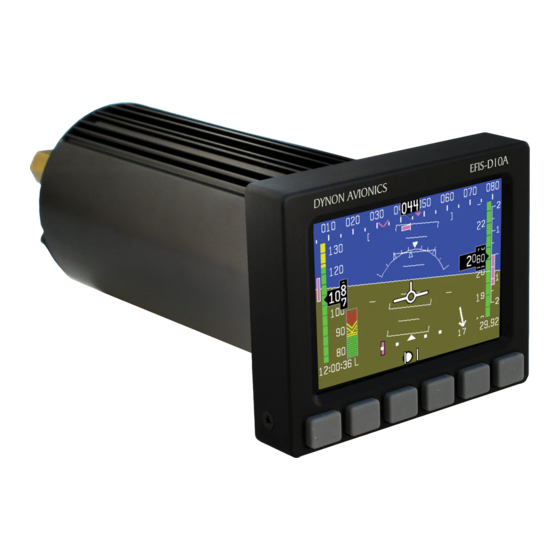
Product Overview DISPLAY The display is a 4-inch, 320 by 240 pixel, 450-nit LCD screen. It is acceptable to have the EFIS-D10A turned on during engine start. BUTTONS AND KNOBS User interaction takes place via the six buttons along the bottom of the front panel of the unit. -
Page 14: An Important Note About Airspeed
AN IMPORTANT NOTE ABOUT AIRSPEED As depicted above, your EFIS-D10A depends on airspeed (pitot and static) for most of the other AHRS indicators. If a problem develops with your airspeed reading, treat all of the instruments on your EFIS with skepticism – especially attitude. -
Page 15: Product Operation
3. PRODUCT OPERATION After reading this section, you will be familiar with the basics of how to use your EFIS-D10A. For details regarding specific procedures (e.g., adjusting display brightness, changing the barometer, setting the clock, etc.) please refer to the EFIS Operation section. - Page 16 Product Operation Display The EFIS-D10A display is the most obvious and commonly used output of the device. It is capable of displaying EFIS, HSI, and/or engine data simultaneously. SCREENS AND PAGES The terms in the following bulleted list are used in this section and are defined as follows: •...
- Page 17 The SCREEN LIST Menu uses icons to illustrate the The predefined screen configurations with their respective icons layout for each screen configuration. are as follows: TIMES/AUX FUEL EFIS (default EFIS-D10A boot-up screen; in default rotation) HSI (in default screen rotation) EFIS-D10A Pilot’s User Guide...
-
Page 18: Cycling Between Screens
LIST menu, from which you may switch important to you. If you wish to access screens that are not in your to, and set up, various screen rotation, use the SCREEN LIST as described above. configurations. EFIS-D10A Pilot’s User Guide... - Page 19 Scroll through the pre-defined screens using the DOWN▼/UP▲ buttons. Press the MV DN▼ button to move the selected screen down in the screen list. Likewise, press the MV UP▲ button to move the selected screen up in the screen list. EFIS-D10A Pilot’s User Guide...
-
Page 20: Menus
1/2 of the screen and the right page occupying 1/2 of the screen, then pressing EFIS-D10A buttons two or three (all below the left 1/2 of the screen) displays the main menu for the left page and pressing buttons four or five (below the right 1/2 of the screen) displays the main menu for the right page (see the figure to the right). -
Page 21: Flow
In any menu with more options than will fit on a line, the MORE button displays the rest of the menu. For example, if you press the BUGS button on the EFIS menu, there are options for HDG, IAS, ALT, EFIS-D10A Pilot’s User Guide... -
Page 22: Descriptions In This Guide
“EFIS > INFO > LEFT” indicates entering the EFIS menu, pressing MORE, then pressing INFO, and then pressing LEFT to enter the left info item menu. Note that the MORE button is not included in the sequence, since pressing MORE reveals more options in the same level of the menu system. EFIS-D10A Pilot’s User Guide... -
Page 23: Available Pages
Note: EMS-based pages use data that is obtained from Dynon’s EMS products. You may only display these pages on your EFIS-D10A if you own a Dynon EMS-based product, and the two units are connected via DSAB. Refer to the EFIS-D10A Installation Manual for details regarding proper connection between Dynon products and other devices in your system. -
Page 24: Efis Main Pages
Available Pages EFIS Main pages Available in full-page format The EFIS-D10A default screen rotation includes only 2/3 EFIS pages combined with the various EMS and HSI pages described below. However, you may also choose screen configurations that use 1/3 and full-screen pages. - Page 25 Unlike a mechanical artificial horizon, the EFIS-D10A’s horizon has no roll or pitch limitation. The horizon line stays parallel to the Earth’s horizon line regardless of attitude. The parallel lines above and below the horizon line are the pitch indicator lines, with each line indicating 5 degrees of pitch.
- Page 26 Like a conventional gyro-stabilized magnetic compass, magnetic heading reacts immediately to turn rate so that heading changes are reflected immediately. It then uses magnetometer data over the long term to ensure that it remains correct. Additionally, heading is corrected for attitude so that it is accurate as you pitch and roll. EFIS-D10A Pilot’s User Guide...
- Page 27 The EFIS-D10A accurately displays altitudes from -1200 to 30,000 ft (-365 to 9144 m). The graphical Vertical Speed Indicator is located next to the altitude tape. The magenta bar grows in the direction of –...
- Page 28 The number indicates the current absolute wind speed in the current airspeed units. If the EFIS-D10A cannot make an accurate winds aloft calculation, the arrow is not displayed and the numbers are replaced by dashes. The display of winds aloft requires an active GPS connection and an OAT probe.
- Page 29 The EFIS-D10A is factory-calibrated to be accurate for airspeeds between 15 and 325 knots (17 to 374 mph). As airspeed increases from 0 knots, the indicator becomes active at 20 knots. The indicator remains active until airspeed drops below 15 knots.
- Page 30 Local time (L), Zulu time (Z), or a timer (T). If a GPS is connected to your Dynon network and is outputting time information, the Zulu time of all connected products is auto-set to that reported by the GPS. EFIS-D10A Pilot’s User Guide...
-
Page 31: Hsi Page
HSI Page Available in 1/2 format Your EFIS-D10A can function as a Horizontal Situation Indicator (HSI) when it is receiving data from Dynon’s HS34 (connected to a nav radio), an external GPS, or Garmin SL30 Nav radio. The HSI information is overlaid on a directional gyro (DG) representation of the EFIS's stabilized magnetic heading information. -
Page 32: Lists Pages
You may define up to twenty-five lists. Each checklist/data panel can contain up to 14 lines of text and 40 characters per line. Checklists/data panels must be defined and uploaded to the EFIS-D10A as described by the Dynon Product Support Program. Reference the help file that accompanies this software for more information. -
Page 33: Menu Pages
Press SEL► to expand the menu into another list of options to the right. Any line on a Menu Page that is not followed by ► indicates that its value can be modified using the SEL►, DOWN▼, and UP▲ buttons. EFIS-D10A Pilot’s User Guide 4-11... -
Page 35: Efis Operation
POWER – Power on/off When the EFIS-D10A is turned off but still has a power source via one of the three power inputs, press the far left button to turn the unit on. Likewise, once the unit is on and no menus are displayed, push and hold the leftmost button to turn it off. -
Page 36: Bugs - Setting Bug Markers
In the BUGS menu, press HDG. Press the TOGGLE button to turn on or off the heading bug display on the horizontal heading tape. Note that this affects the display of the heading bug on the HSI page as well. EFIS-D10A Pilot’s User Guide... -
Page 37: Airspeed
The airspeed bug can be adjusted on any EFIS page in the system and is synchronized across all EFIS-based units. When in the BUGS > IAS menu, rotate the HS34’s VALUE knob to quickly change the bug’s set value. EFIS-D10A Pilot’s User Guide... -
Page 38: Altitude
The visual climb or descend alert clears after recapturing the target altitude or 30 seconds. Flying back inside the 150- foot capture window re-arms the alerter without any user interaction. If your system is configured to output voice via the HS34 module, the voice alerts “climb” or “descend” are sounded, instead of tones. EFIS-D10A Pilot’s User Guide... -
Page 39: Lists - Using Checklists And Data Panels
The Dynon Support Program allows you to enter your own checklists or select from included data panels. These checklists and data panels can then be uploaded to your EFIS-D10A for quick access from the main menu or from your screen rotation. Data panels and checklists can be included beneath 5 user-configurable categories and each category can contain up to 5 checklists or data panels. -
Page 40: Setup - Setting Preferences
Enter the EFIS > SETUP menu to make changes to preferences. Many of the settings in this menu should only be changed by the installer, and are described in the EFIS-D10A Installation Guide. The preferences and settings that are relevant to the pilot and in-flight operation are explained below. - Page 41 SEL► moves the highlight to the next set of digits. The order of selection is 1. Local hours, 2. Local minutes (adjustable only as ½-hour offsets from Zulu minutes), 3. Zulu hours, 4. Zulu minutes. When connected to a GPS, you are not permitted to adjust the Zulu time on the EFIS-D10A •...
-
Page 42: Show/Hide Display Items
Toggles the display of the current barometer setting (also known as the Kollsman setting). This display is not required to set the barometer. While in the EFIS > BARO menu, a separate value-setting box appears, allowing adjustments to be made. EFIS-D10A Pilot’s User Guide... - Page 43 Toggles the display of the ground track indicator on the heading tape. The track indicator is a magenta arrow and is only displayed when the EFIS-D10A is receiving valid GPS data from an external source. If the GTRK button status displays “Y”...
-
Page 44: Check Firmware Version
The EFIS > SETUP > VRSION menu gives you two important pieces of information: your EFIS-D10A’s current firmware version; and the number of hours the EFIS-D10A has been on. If you require technical support or other assistance from Dynon, please have your firmware version ready when you call or write. - Page 45 The top row, labeled MX, is the maximum positive g-force experienced by the EFIS-D10A since reset. The middle row, labeled CR, is the current g-force experienced by the EFIS-D10A. The bottom row, labeled MN, is the minimum g-force experienced by the EFIS- D10A since reset.
- Page 46 When multiple units are connected to a DSAB network, one primary OAT is shared between all units. This can be an OAT connected to an EFIS or an EMS. If the EFIS-D10A is displaying an OAT provided by another unit in the system, changing the OAT type or install status on the EFIS-D10A has no effect on the displayed OAT.
-
Page 47: Dim - Changing Screen Brightness
In the EFIS > DIM menu, press BRITR or DRKR to change the brightness of the display. It is not possible to turn the screen completely black. Note that if power to the EFIS-D10A is cycled, the screen is reset to full brightness. -
Page 48: Oatset - Setting Temperature Offset
If you did not purchase an EFIS or EMS outside air temperature sensor from Dynon Avionics, you may still manually adjust the OAT to an approximate value. With this manually entered information, the EFIS-D10A calculates and displays true airspeed (TAS) and density altitude as it does when an OAT is connected. Ensure that you have indicated that an EFIS OAT is not installed;... -
Page 49: Hsi Operation
30 Nav/Comm radio via a serial connection (Nav data), a Garmin GNS-430/530 GPS/Nav/Comm (GPS data), or any GPS that outputs in either NMEA-0183 or aviation format. Please refer to the EFIS-D10A Installation Guide for instructions on how to connect these devices to your Dynon network. Also, ensure your GPS device is configured to output magnetic heading since all calculations and displays are done in reference to the local magnetic heading. -
Page 50: Accessing The Hsi/Dg Page
Accessing the HSI/DG Page The HSI is displayed as a full-screen page on your EFIS-D10A. If the HSI is defined as part of a screen setup in your rotation, display the HSI page using either of the screen rotation hotkeys (buttons 1 and 6) until the appropriate page is displayed. - Page 51 2. Digital heading indicator. The number in this box is the current magnetic heading of the aircraft in degrees from 001 to 360. The accuracy of this data depends on the accuracy of the heading calibration for your EFIS-D10A. EFIS-D10A Pilot’s User Guide...
- Page 52 It uses the GPS ground speed and track to compare to the magnetic heading and the true airspeed that the EFIS calculates. In order for winds to be correct, the airspeed, OAT, and compass on the EFIS must all be accurate. EFIS-D10A Pilot’s User Guide...
-
Page 53: Navigation Radio Overlay
When using the HS34 you can set the OBS using the course knob; the HS34 can communicate with the NAV radio instead of just receiving data from it, as with a standard serial connection. The HS34 sends the course EFIS-D10A Pilot’s User Guide... - Page 54 The primary bearing indicator is depicted by a yellow diamond and the standby indicator is depicted by an orange circle. These elements only appear when the active and/or standby VORs are tuned to an active frequency. A numerical display of your EFIS-D10A Pilot’s User Guide...
-
Page 55: Gps Overlay
This indicator is fixed to the rotation of the DG, so it is easy to see which way you must turn EFIS-D10A Pilot’s User Guide... - Page 56 If you have two or more bearing sources, pressing the BRG SRC button highlights the first bearing source. Turning the value knob allows you to choose your bearing source from all options. Pressing the bearing source again chooses the second bearing EFIS-D10A Pilot’s User Guide...
- Page 57 As long as a valid GPS source is detected by the system, the ground track indicator can be displayed. This is not dependent on the currently set nav source. EFIS-D10A Pilot’s User Guide...
-
Page 58: Hsi Menu Structure
If the GPS or NAV device is in a mode where it is ignoring course commands, turning the course knob results in no change on the screen. This is true when you are in most GPS modes. 6-10 EFIS-D10A Pilot’s User Guide... - Page 59 HSI Operation SCALE (GPS mode) - This is used to cycle through the three GPS scale modes. The scale button only exists if the source you are connected to is not providing scale information. EFIS-D10A Pilot’s User Guide 6-11...
-
Page 61: Alerts
Note that alarms may not be acknowledged during the initial two seconds of the first alarm. In an alarm condition, the EFIS-D10A does not alert you audibly. The audio out connection on the EFIS-D10A is for AOA alerts only. If you have a Dynon EMS-based product installed, connected to both your EFIS-D10A and cockpit audio system, EMS-based alarms will still sound an audible alarm. -
Page 62: Show Page
When acknowledging a voice alert from the HS34, the full text of the current alarm is read before it is silenced; no other queued alarms will be announced after that. Multiple Alarms Any time multiple alarms occur in quick succession, they are handled in the following way: EFIS-D10A Pilot’s User Guide... -
Page 63: Dsab Alerts
SETUP > DSAB > STATUS. If a unit is purposefully removed from the system, refer to the EFIS-D10A Installation Guide for instructions on reconfiguring the network. - Page 64 If the HS34 is not communicating on DSAB properly, both the NAV and GPS lights are illuminated. During normal system operation both lights will never be illuminated simultaneously; dual illumination indicates a communication failure. Additionally, if the DSAB network fails in flight “DSAB ERROR” will be annunciated via HS34’s the audio output. EFIS-D10A Pilot’s User Guide...
-
Page 65: Appendix
The EFIS-D10A has one RS232 serial port which outputs EFIS data. Technical information on the installation and connection to these serial ports can be found in the EFIS-D10A Installation Guide. To log EFIS data, you must connect the serial port to a PC. This serial data can be logged using any standard serial terminal program such as HyperTerminal®. -
Page 66: Efis Serial Data Output
Description Notes Char Hour 00 to 23, current Zulu time hour according to EFIS-D10A’s internal clock. Minute 00 to 59, current Zulu time minute according to EFIS-D10A’s internal clock. Second 00 to 59, current Zulu time second according to EFIS-D10A’s internal clock. -
Page 67: Appendix B: Pc Support Program
Appendix C: Troubleshooting See the EFIS-D10A Installation Guide Appendix for a variety of troubleshooting tips and solutions. You may also reach us and other active users at our online support forums located at: www.dynonavionics.com/forum/. -
Page 68: Alert Messages
EFIS-D10A’s firmware version number ready when you contact us. To locate your product’s firmware version, refer to the Check firmware version section on page 5-10. See the following list of alert messages displayed by the EFIS-D10A. The list provides information about what they mean and what to do about them. - Page 69 This alert can only be triggered when airspeed is non-zero; using the EFIS-D10A on the bench will not trigger this alert. HOLD TO POWER This alert appears when you have pressed the...
- Page 70 Alert Message Meaning End condition OAT SENSOR NOT This alert appears when the EFIS-D10A has an Double-check your wiring between the EFIS- DETECTED OAT connected and then loses that connection for D10A and the EDC-D10A as well as that of the some reason.
- Page 71 The best way of ensuring this is to call Dynon Avionics immediately. However, there is a good possibility that the unit will have to be returned for service. EFIS-D10A Pilot’s User Guide...
- Page 72 Appendix Appendix D: EFIS-D10A Specifications Mounting: Fits into standard 3 1/8” panel hole Optional flush mount bracket available Mechanical Weight: 1 lb. 9 oz. (700 g) 1 lb. 15 oz. (880 g) with internal battery -22° to 122° F (-30° to 50° C)
Need help?
Do you have a question about the EFIS-D10A and is the answer not in the manual?
Questions and answers