
Related Manuals for Dynon Avionics EMS-D120


Summary of Contents for Dynon Avionics EMS-D120
- Page 1 EMS-D120 Engine Monitoring System Pilot’s User Guide P/N 100592-000, Revision H For use with firmware version 5.4 August, 2010 Dynon Avionics This product is not approved for installation in type certificated aircraft...
-
Page 2: Copyright
Contact Information Dynon Avionics, Inc. 19825 141 Place NE Woodinville, WA 98072 Phone: (425) 402-0433 - 7:00 AM – 5:00 PM (Pacific Time) Monday - Friday Fax: (425) 984-1751 Dynon Avionics offers online sales, extensive support, and continually-updated information on its products via its Internet sites: ... - Page 3 Units that have been found to have been taken apart may not be eligible for repair under warranty. Additionally, once a Dynon Avionics unit is opened up, it will require calibration and verification at our Woodinville, WA offices before it can be considered airworthy. EMS-D120 Pilot’s User Guide...
-
Page 4: Table Of Contents
About this Guide................................1-2 Product Overview EMS-D120 Hardware ................................2-1 Product Operation Front Panel Layout ................................3-1 Display....................................3-2 Menus ....................................3-6 Available Pages EMS Main Pages ................................4-2 EMS Auxiliary Page................................4-3 EMS Times Page ................................4-3 EMS Fuel Computer Page ..............................4-4 Lists Pages ..................................4-5 EMS-D120 Pilot’s User Guide... - Page 5 Engine Leaning................................. 7-3 Clock Setup..................................7-3 Timers....................................7-4 Global Configuration Settings ............................7-5 Appendix Appendix A: Serial Data Output............................8-1 Appendix B: PC Support Program............................ 8-5 Appendix C: Troubleshooting ............................8-5 Appendix D: EMS-D120 Specifications........................... 8-6 EMS-D120 Pilot’s User Guide...
-
Page 6: Introduction
OEM Installations If your EMS-D120 is installed by an OEM distributor, you may find that you are unable to access some menus and settings. Some Dynon distributors customize various areas of the EMS-D120 firmware to maintain a consistent pilot experience and minimize integration issues across a large number of installations. -
Page 7: Warning
About this Guide This guide serves two purposes. The first is to help you configure and get acquainted with the EMS-D120‘s many functions. The second is to give you quick access to vital information. For detailed technical and installation information, please refer to the EMS-D120 Installation Guide. - Page 8 Any text following this icon describes functionality that is possible when multiple Dynon Avionics products are networked together via the Dynon Smart Avionics Bus (DSAB). Any text following this icon refers to a setting or situation which merits particularly close attention. EMS-D120 Pilot’s User Guide...
-
Page 9: Product Overview
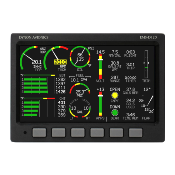
This EMS-D120 monitors your engine and other vital aircraft systems and displays information in an easy-to-read format. This section provides a general overview of the various parts of the EMS-D120 as well as a theory of operation. The information in this section serves as a reference only and helps familiarize you with the inner workings of the unit. It should not be used for diagnostic or reparative work. - Page 10 The EMS-D120 has outputs to drive external customer-supplied audible and visual devices for engine, AOA (if installed) and altitude alerts. A connected HS34 or AP74 can output voice annunciations for many of the alerts generated by the EMS-D120. DISPLAY The display is a 7-inch, 854 by 480 pixel, 400 nit or 800 nit LCD screen, depending on the model.
-
Page 11: Product Operation
3. PRODUCT OPERATION After reading this section, you will be familiar with the basics of how to use your EMS-D120. For details regarding specific procedures (e.g., adjusting display brightness, using the fuel computer, setting the clock, etc.) please refer to the EMS Operation section. - Page 12 Product Operation Display The EMS-D120 display is the most obvious and commonly used output of the device. It is capable of displaying EFIS, HSI, and/or engine data simultaneously. SCREENS AND PAGES The terms in the following bulleted list are used in this section and are defined as follows: ...
- Page 13 The SCREEN LIST Menu uses icons to illustrate the layout for each screen configuration. EFIS/EMS EFIS/AUX EFIS/FUEL EFIS/TIMES EFIS/HSI EMS/EFIS EMS/AUX (default EMS-D120 boot-up screen; in default rotation) EMS/TIMES (in default screen rotation) EMS/FUEL EMS/HSI EFIS EFIS/EMS EMS/EFIS HSI/EMS EMS-D120 Pilot’s User Guide...
- Page 14 They are meant to give you quick access to the screen screen configurations. configurations that are most important to you. If you wish to access screens that are not in your rotation, use the SCREEN LIST as described above. EMS-D120 Pilot’s User Guide...
- Page 15 Press SETUP, then press ORDER to display the menu used to change the screen order. Scroll through the pre-defined screens using the DOWN▼/UP▲ buttons. Press the MV DN▼ EMS-D120 Pilot’s User Guide...
-
Page 16: Menus
Likewise, press the MV UP▲ button to move the selected screen up in the screen list. Menus All interaction with the EMS-D120 is accomplished through the use of its menu system. The menu system is accessed and navigated via the six buttons located on the front of the unit. - Page 17 MENU►. Pressing the button switches the menu to display the right page’s menu, and the label switches to read ◄MENU. The arrow on this button always points to the side of the screen whose menu is displayed when pressing the button. EMS-D120 Pilot’s User Guide...
- Page 18 “EMS > SETUP > CLOCK” indicates entering the EMS menu, pressing MORE, then pressing SETUP, and then pressing CLOCK to enter the clock adjustment menu. Note that the MORE button is not included in the sequence, since pressing MORE reveals more options in the same level of the menu system. EMS-D120 Pilot’s User Guide...
- Page 19 Note: EFIS-based pages use data that is obtained from Dynon’s EFIS products. You may only display these pages on your EMS-D120 if you own a Dynon EFIS-based product, and the two units are connected via DSAB. Refer to the EMS-D120 Installation Manual for details regarding proper connection between Dynon products and other devices in your system.
-
Page 20: Ems Main Pages
CHTs are displayed using their own set of green bars on a different scale than EGTs with their respective numeric values displayed to the right of each bar. When displayed as a 1/3 page, with the exception of two cylinder engines, the EGT/CHT display is shown in combined mode. EMS-D120 Pilot’s User Guide... -
Page 21: Ems Auxiliary Page
The Flight Timer shows the total amount of time that oil pressure is above 15 PSI since the EMS-D120 was turned on; it does not reset until the next time the EMS-D120 is power-cycled and oil pressure reaches 15 PSI. The Trip Timer shows cumulative flight time since a manual reset. -
Page 22: Ems Fuel Computer Page
This allows you to view the fuel used value from your last flight. Some user input is required for the EMS-D120 Fuel Computer to function properly. Refer to EMS Operation on page 7-2 for instructions on adjusting various Fuel Computer parameters. -
Page 23: Lists Pages
Each checklist/data panel can tain up to 14 lines of text and 40 characters per line. Checklists/data panels must be defined and uploaded to the EMS-D120 as described by the Dynon Product Support Program, available at downloads.dynonavionics.com. Reference the help file that accompanies this software for more information. -
Page 24: Alerts
In an alarm condition, the EMS-D120 also alerts you audibly, provided the EMS Audio Alert output is connected to your intercom as described in the EMS-D120 Installation Guide. If no audio device is connected, you will not hear an audible alarm. - Page 25 If this number is higher than 1, after yo u press ACK the alarm text for the next posted alarm is displayed in the alarm bar. Pre ssing ACK does the following: Silences the audio alarm EMS-D120 Pilot’s User Guide...
-
Page 26: Multiple Alarms
6. Pressing SILNCE removes the audio alert for th e displayed pending alarm. 7. Once the top alarm is acknowledged, the next alarm in the stack is shown, triggering the audio alarm again. EMS-D120 Pilot’s User Guide... -
Page 27: Latching And Self-Clearing Alarms
Latching and Self-clearing Alarms Depending upon how your EMS-D120 was set up, some of the sensors’ alarms may be set to be latching, while others may be self-clearing. The distinction is described below. See the EMS-D120 Installation Guide for more information configuring this setting for each alarm. - Page 28 SETUP > DSAB > STATUS. If a un it is purposefully removed from the system, refer to the EMS-D120 Installation Guide for instructions on reconfiguring th network.
-
Page 29: Ems Monitoring Functions
6. EMS MONITORING FUNCTIONS This section describes just a few of the advanced ways to use your EMS-D120 to monitor the operation of your engine. Engine Leaning and Power The engine monitor provides multiple methods to assist you in setting the mixture of your engine for various functions. -
Page 30: Data Logging
The EMS-D120 provides two options for logging data. You may configure the EMS-D120 to log data to its internal memory for later retrieval or you may record streaming data serial output to an external device (such as a laptop computer) in real-time from the serial port. - Page 31 30 minutes of cumulative data can be recorded; with a 10-second interval, at least 5 hours; with a 30-second interval, at least 15 hours, and with a 60-second interval, at least 30 hours. When the EMS-D120 internal storage fills up, new records overwrite the oldest records.
- Page 32 EMS-D120 in real-time a laptop (or other serial data collection device) must be connected to the serial port(s) of the EMS-D120. The data format and connection settings are described on page 8-1. EMS-D120 Pilot’s User Guide...
-
Page 33: Ems Operation
It enters a low-power state, and keeps track of time as well as detects changes in the state of button one (the POWER button). It is acceptable to have the EMS-D120 on during engine crank. It immediately powers on upon application of external power. -
Page 34: Fuel Computer
When this is configured, the next time you turn the FlightDEK-D180 on, it asks you if you added fuel and gives you a shortcut to the add fuel menu. See the EMS-D120 Installation Guide for more information on configuring the fuel sensors and fuel computer. -
Page 35: Engine Leaning
Highlight values using SEL►. Adjust highlighted values with INC+/DEC-. Each time a button is pressed, the value changes by one. Hold down INC+ or DEC- to adjust values rapidly. Seconds are reset to zero when EMS-D120 Pilot’s User Guide... -
Page 36: Timers
When connected to a GPS which is outputting time information, Zulu time is synchronized to the GPS and cannot be set on the EMS-D120. In a DSAB network, you can only set the Zulu time on the DSAB master, and only if it is not synchronized to GPS time. -
Page 37: Global Configuration Settings
SERIAL PORT. Pilot settings and screen settings are addressed in this guide. If you or your installer have completed the procedures outlined in the EMS-D120 Installation Guide, you do not need to modify anything in the other sections. Scroll between settings by using the UP▲/ DOWN▼ buttons. Chosen settings are highlighted. Toggle between parameter settings or display a menu of choices by pressing SEL►. - Page 38 Info item 1 is at the top right of the page, and info item 2 is at the lower right of the page. The other six info items are located on the Aux Page and are numbered 3 through 5 on the top row EMS-D120 Pilot’s User Guide...
- Page 39 The HS34 has 3 general purpose inputs and 4 contact inputs. The data obtained from these inputs can be configured and displayed on any EMS page in the system. In the event of a DSAB or HS34 failure, data obtained from the HS34 inputs will be marked as invalid on screen. EMS-D120 Pilot’s User Guide...
-
Page 40: Appendix
The EMS-D120 outputs text data through its serial port constantly during normal operation. Technical information on the installation and connection to this serial port can be found in the EMS-D120 Installation Guide. To log EMS data you must connect the serial port to a PC. This serial data can be logged using any standard serial terminal program such as HyperTerminal®. - Page 41 3 char label; 5 char data; see GP output table GP_3 See table below 3 char label; 5 char data; see GP output table GP Thermocouple ºF 1234 (1234 F) or –123 (-123ºF ) EGT_1 ºF 1234 (1234 F) or –123 (-123ºF ) EMS-D120 Pilot’s User Guide...
- Page 42 ‘0’ or ‘1’ indicating whether the contact is closed Contact_2 or open Product ID ASCII hex Internal-use product ID ASCII hex The self-zeroing ascii-hex 2-byte checksum. The Checksum sum of the checksum with all preceding bytes produces 0x00. 0x13 0x10 EMS-D120 Pilot’s User Guide...
- Page 43 0061 (61%) deflection Elevator Trim % of full 0061 (61%) deflection Rudder Trim % of full 0061 (61%) deflection Flap Position º 00010 (10º) As an example, the following is one line of EMS data: 0012224826351340262441240122631320562191191OAT00090TRE-0061FLP0001020481378139214 061421143514503583533633743843951103D2 EMS-D120 Pilot’s User Guide...
-
Page 44: Appendix B: Pc Support Program
Appendix C: Troubleshooting See the EMS-D120 Installation Guide Appendix for a variety of troubleshooting tips and solutions. You may also reach us and other active users at our online support forums located at: forum.dynonavionics.com. -
Page 45: Appendix D: Ems-D120 Specifications
Appendix Appendix D: EMS-D120 Specifications Mounting: 6.95” wide x 4.90” tall x 4.51” deep (177 x 125 x 115 mm) Mechanical Weight: 2 lb. 6 oz. (1.08 kg) -22° to 122° F (-30° to 50° C) Operating Temperature Voltage: 10 - 30 Vdc... - Page 46 Coolant Temp, Coolant Press, Carburetor Temp, Flaps, Trim) 1 - Alarm Light Contact 2 - Audio Alarm 1 - RS-232 bidirectional PC communication or external data input Inputs/Outputs 1 - RS-232 data input (GPS, SL30, etc.) 2 - Dynon Smart Avionics Bus (DSAB) EMS-D120 Pilot’s User Guide...
Need help?
Do you have a question about the EMS-D120 and is the answer not in the manual?
Questions and answers