Table of Contents
Advertisement
Quick Links
Advertisement
Table of Contents

Related Manuals for Soltech SFC8000HP


Summary of Contents for Soltech SFC8000HP
- Page 1 SFC8000HP User’s Manual_V1.0.0.6...
-
Page 2: Table Of Contents
2.5 Connecting I/O port ..........................23 3. Installation of bracket ................24 4. Installation of product ................26 4.1 Installation of SFC8000HP ........................26 4.2 Installation of SFP module ........................27 4.3 Connecting optical cable ......................... 28 4.4 Removing transceiver module ......................28 5. - Page 3 SFC8000HP User’s Manual_V1.0.0.6 5.2 Web screen configuration ........................31 5.3 System ................................32 5.3.1 Information ............................33 5.3.1.1 Information Configuration ..................... 33 5.3.1.2 Information status ......................34 5.3.2 IP Configuration ..........................36 5.3.2.1 IP Configuration ......................... 36 5.3.2.2 DHCP Configuration ......................37 5.3.2.3 IP Status ..........................
- Page 4 SFC8000HP User’s Manual_V1.0.0.6 5.3.5.3 SSH ............................50 5.3.5.4 HTTPS ............................51 5.3.5.5 Access Management ......................52 5.3.5.6 Auth Method ........................55 5.3.5.7 AAA ............................56 5.3.5.8 NAS ............................67 5.3.5.9 Port Security ......................... 76 5.3.6. Green Ethernet ..........................80 5.3.6.1 LED ............................80 5.3.6.2 Port Power Savings ......................
- Page 5 SFC8000HP User’s Manual_V1.0.0.6 5.5.2 Status..............................98 5.5.2.1 Port State ..........................98 5.5.2.2 SFP Moudule Information.................... 100 5.5.2.3 Traffic Overview ........................ 101 5.5.3.4 Detailed Statistics ......................102 5.5.3 Mirroring ............................104 5.5.4 Loop protection..........................106 5.5.4.1 Configuration ........................106 5.6.4.2 Status ............................. 107 5.5.5 Limit Control ...........................
- Page 6 SFC8000HP User’s Manual_V1.0.0.6 5.6.2 Status..............................137 5.6.2.1 VLAN Membership ......................137 5.6.2.2 VLAN Port ........................... 138 5.6.2.3 VCL ............................139 5.7 QoS .................................. 140 5.7.1 Configuration ..........................140 5.7.1.1 Port Classification ......................141 5.7.1.2 Port Policing ........................143 5.7.1.3 Queue Policing ......................... 144 5.7.1.4 Port Scheduler ........................
- Page 7 SFC8000HP User’s Manual_V1.0.0.6 5.7.2.2 QCL Status .......................... 162 5.8 Protocol ................................164 5.8.1 Ring Protocols ..........................165 5.8.1.1 S-RING ..........................165 5.8.1.2 Spanning Tree ........................166 5.8.1.3 ERPS ............................182 5.8.2 Aggregation ............................ 203 5.8.2.1 Static ............................203 5.8.2.2 LACP ............................205 5.8.3 IPMC ..............................
- Page 8 SFC8000HP User’s Manual_V1.0.0.6 5.8.4.7 Access ............................ 241 5.8.5 RMON ..............................243 5.8.5.1 Configuration ........................243 5.8.5.2 Status ............................. 249 5.8.6 Discovery Protocols ........................255 5.8.6.1 LLDP ............................255 5.8.6.2 UPnP ............................273 5.8.7 Inspection ............................274 5.8.7.1 DHCP ............................. 274 5.8.7.2 IP Source Guard .......................
- Page 9 SFC8000HP User’s Manual_V1.0.0.6 5.10.3.2 Image Select ........................302 5.10.4 Configuration ..........................304 5.10.4.1 Save ............................. 304 5.10.4.2 Upload ..........................304 6. Consol setting(Telnet, SSH) ..............305 7. Scan manager ..................309 8. Maintenance Inspection ..............309 8.1 surveillance center Maintenance ......................311 8.2 ethernet switch maintenance ......................
-
Page 10: Introduction
Gigabit Ethernet Switch can transmit a huge data through 20Gbps internal Switch fabric into backbone or high-power servers in security topology. SFC8000HP can find 8K MAC address, provides wired Packet transmit function without any packet loss. Its high throughput of data provides convenience to users when upgrade to Gigabit network. -
Page 11: Product Sepcification
SFC8000HP User’s Manual_V1.0.0.6 1.2 PRODUCT SEPCIFICATION ○ Physical Port 8port 10/100/1000M Base-T ⬧ 2port SFP slots Port 9 and Port 10 ⬧ Reset button for system management ⬧ ○ Generic Features Comply with IEEE802.3, 10Base-T, IEEE 802.3u, 100Base-TX, IEEE 802.3ab, ⬧... - Page 12 SFC8000HP User’s Manual_V1.0.0.6 Prevents packet loss with back pressure (half-duplex) and 802.3x PAUSE ⬧ frame flow control (Full-duplex) 8K MAC address table, automatic source address learning and ageing ⬧ 20Gbps Switch fabric, non-blocking Switch architecture ⬧ Up to 10K Bytes Jumbo frame support at all speed (10/100/1000 Mbps) ⬧...
- Page 13 SFC8000HP User’s Manual_V1.0.0.6 Firmware upgrade through web interface ⬧ Cable Diagnostics technology ⬧ Support SNMPv1 with RFC-1213/1573-Interface group, Ethernet MIB ⬧ SNMP Trap ⬧ ○ Power over Ethernet Complies with IEEE 802.3af / IEEE 802.3at Power over Ethernet End-Span ⬧...
- Page 14 SFC8000HP User’s Manual_V1.0.0.6 PRODUCT SPECIFICATION Hardware Specification Copper ports 8-Port 10/100/1000 Base-T Auto MDI/MDI-X SFP Slots 2-Port 100M/1000M/2.5G Base-SX/LX Switch architecture Store-and-Forward Switch backbone 20Gbps Switch throughput 14.8Mpps MAC Address Table 8K entries Data Buffer 512KB On-chip frame buffer Back pressure for half duplex, IEEE 802.3x Pause Frame for full...
- Page 15 SFC8000HP User’s Manual_V1.0.0.6 < 10sec : Default Reset (keep ip address) > 10sec : Factory Reset (reset ip address to default ip) Alarm Contact 1 relay output with current carrying capacity of 12~24VDC @ 1A 1 input with the same ground, but electrically isolated Digital Input from the electronics.
- Page 16 SFC8000HP User’s Manual_V1.0.0.6 IEEE 802.3ad LACP / Static Trunk Link Aggregation Supports 5 groups of 8-Port trunk support 4 Priority Queue and traffic classification based on 802.1p priority, DSCP field in IP packet IGMP (v1/v2/v3) Snooping, up to 255 multicast Groups...
- Page 17 SFC8000HP User’s Manual_V1.0.0.6 RFC-2819 RMON MIB (Group 1,2,3,9) RFC-2737 Entity MIB RFC-2618 RADIUS Client MIB RFC-2933 IGMP-STD_MIB RFC3411 SNMP-Frameworks-MIB IEEE 802.1X PAE LLDP MAU_MIB ERPS Carrier Ethernet Standards Conformance IEEE 802.3 10Base-T Ethernet IEEE 802.3u 100Base-TX/100Base-FX Fast Ethernet IEEE 802.3z Gigabit Ethernet (SX/LX) IEEE 802.3ab Gigabit 1000T...
- Page 18 SFC8000HP User’s Manual_V1.0.0.6 IEEE 802.1p Class of service IEEE 802.1Q VLAN Tagging IEEE 802.1x Port Authentication Network Control IEEE 802.1ab LLDP RFC 768 RFC 793 TFTP RFC 791 RFC 792 ICMP RFC 2068 HTTP RFC 1112 IGMP version 1 RFC 2236 IGMP version 2 Operating Temperature -40~80°C...
-
Page 19: Contents
SFC8000HP User’s Manual_V1.0.0.6 PoE Power Supply Type End-Span PoE Power output Per port 52V DC, 600mA Max. 30 Watts PoE Power Budget 250W Max. number of Class 4 PD 1.3 CONTENTS Managed Industrial Gigabit Ethernet Switch X 1 ⚫ User Manual CD X 1 ⚫... -
Page 20: Exterior
SFC8000HP User’s Manual_V1.0.0.6 Wall Mount bracket, DIN-Rail Mount bracket, Screw Note : Please re-package all of contents. 2. EXTERIOR Exterior 2.1 SIZE SFC8000HP’s size is 61mm(W) X 110mm(D) X 157mm(H). 2.2 FRONT PANEL... -
Page 21: Led Condition
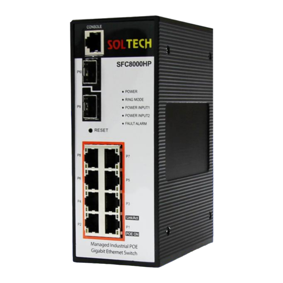
SFC8000HP User’s Manual_V1.0.0.6 There are 8pcs of RJ-45 10/100/1000Mbps ports, 2pcs of 100M/1000M/2.5GBase-SX/LX optical ports. CONSOLE port is for setting the device. 2.3 LED CONDITION Front LED indicators of SFC8000HP ⚫ Color Function Power Green Switch powered Power Green Power input into Power Input1... -
Page 22: Connect Power Input
SFC8000HP User’s Manual_V1.0.0.6 P1, P2, P3, Green Lights : 10/100/1000 link on / Blinks : Data transmitting P4, P5, P6, YELLOW Lights : PoE function on P7, P8 SFC8000HP LED panel Notice: If you push a RESET button of Gigabit Ethernet Switch more than 2 seconds, all LEDs are flickering and every setting value(excluding IP address) will be initialized. -
Page 23: Connecting I/O Port
SFC8000HP User’s Manual_V1.0.0.6 Bottom Panels of SFC8000HP Power Notice: 1. The device needs power; it does not work until power is supplied. If your network has to work always, Please use an UPS(Uninterrupted Power Supply) to prevent data loss or stopping the device. -
Page 24: Installation Of Bracket
Installation of bracket INSTALLATION OF BRACKET Wall Mount bracket and DIN-Rail Mount bracket are enclosed as a basic contents of SFC8000HP. SFC8000HP can be installed on the wall or DIN-rail using these brackets. To install the bracket, please refer the pictures below. - Page 25 SFC8000HP User’s Manual_V1.0.0.6 Wall mount bracket DIN-Rail mount bracket...
-
Page 26: Installation Of Product
This section explains how to install Gigabit Ethernet Switch and how to connect switch. Please refer below process to finish installation of Gigabit Ethernet Switch. 4.1 INSTALLATION OF SFC8000HP Step 1: Prepare 52~56VDC 10W power supply and SFC8000HP. Step 2: Please keep some spaces between Gigabit Ethernet Switch and surrounding objects for ventilation. -
Page 27: Installation Of Sfp Module
SFC8000HP User’s Manual_V1.0.0.6 4.2 INSTALLATION OF SFP MODULE Note: SFP transceiver is hot-pluggable and hot-swappable. Uses must turn off Gigabit Ethernet Switch when you plug in or plug out SFP modules. Plug-in the SFP transceiver Please check below before connecting other switch, work station or media converter. -
Page 28: Connecting Optical Cable
SFC8000HP User’s Manual_V1.0.0.6 -> If you connect 1000BASE-SX SFP transmission, users have to use multi-mode fiber optic cable, duplex LC type. -> If you connect 1000BASE-LX SFP transmission, users have to use single-mode fiber optic cable, duplex LC type. 4.3 CONNECTING OPTICAL CABLE 1. - Page 29 SFC8000HP User’s Manual_V1.0.0.6 Pull out the SFP transceiver Notice: Please d o not pull out the SFP transceiver wildly. It can damage the Gigabit Ethernet Switch or SFP slot.
-
Page 30: Web Managedment System
5.1 WEB LOGIN WEB management of SFC8000HP sets as follow. 1. Users must know IP Address of SFC8000HP to WEB set. 2. Connect AP (LAN interface) with PC (LAN port) using enclosed LAN cable. 3. Access WEB using IP address of AP. -
Page 31: Web Screen Configuration
SFC8000HP User’s Manual_V1.0.0.6 5.2 WEB SCREEN CONFIGURATION s-ring configration/Port state/ LogOut/ Help Model name 메뉴화면 Web menu Setting and checking of web functions [Panel Display] Shows port image of switch which is controlled by web. It can be set to indicate information of port including mode, uplink and down link. -
Page 32: System
SFC8000HP User’s Manual_V1.0.0.6 System This section provides configuration of System ◼ information. MAC Table This section provides configuration of MAC information. ◼ Ports This section provides configuration of Port information. ◼ VLANs This section provides configuration of VLAN information. ◼... -
Page 33: Information
SFC8000HP User’s Manual_V1.0.0.6 Syslog Setting and checking log message. ◼ Security Setting and checking security of switch. ◼ Green Ethernet Setting and checking LED brightness or power saving. ◼ Checking PoE information, PoE working and PoE ◼ schedule. Digital I/O Setting and checking Digital I/O. -
Page 34: Information Status
SFC8000HP User’s Manual_V1.0.0.6 characters are permitted as part of a name. The first character must be an alpha character. And the first or last character must not be a minus sign. The allowed string length is 0 to 255. The physical location of this node(e.g., telephone closet, System Location 3rd floor). - Page 35 SFC8000HP User’s Manual_V1.0.0.6 Object Description Contact The system contact configured in Configuration | System | ⚫ Information | System Contact. Name The system name configured in Configuration | System | ⚫ Information | System Name. Location The system location configured in Configuration | System | ⚫...
-
Page 36: Ip Configuration
SFC8000HP User’s Manual_V1.0.0.6 5.3.2 IP CONFIGURATION Can set IP address. Users can choose between dynamic IP address and static IP address. 5.3.2.1 IP Configuration Can set IP address, Subnet Mask, Gateway, DNS. Object Description Mode Set IP Static, DHCP. ⚫... -
Page 37: Dhcp Configuration
SFC8000HP User’s Manual_V1.0.0.6 Router Set IP which is connected router to IPv6. ⚫ Link-Local Adress Show connected link-local address value. ⚫ Set DNS. ⚫ Buttons : Click to save changes. : Click to undo any changes made locally and revert to previously saved values. -
Page 38: Ip Status
SFC8000HP User’s Manual_V1.0.0.6 Object Description Mode Set IP Static, DHCP. ⚫ Set DNS. ⚫ Buttons : Click to save changes. : Click to undo any changes made locally and revert to previously saved values. 5.3.2.3 IP Status This page displays the status of the IP protocol layer. The status is defined by the... -
Page 39: Time
SFC8000HP User’s Manual_V1.0.0.6 Object Description Interface The name of the interface. ⚫ Type The address type of the entry. This may be LINK or IPv4. ⚫ Address The current address of the interface (of the given type). ⚫ Status The status flags of the interface (and/or address). - Page 40 SFC8000HP User’s Manual_V1.0.0.6 Object Description NTP Mode Indicate using NTP or not. ⚫ System time Indicate Systime Time ⚫ Year Setting year of System Time ⚫ Month Setting month of System Time ⚫ Date Setting date of System Time ⚫...
-
Page 41: Ntp
SFC8000HP User’s Manual_V1.0.0.6 : Click to undo any changes made locally and revert to previously saved values. : Click to move to NTP : Click to refresh 5.3.3.2 NTP Configure NTP on this page. Object Description Indicates the NTP mode operation. Possible modes are: Mode Enabled: Enable NTP client mode operation. -
Page 42: Time Zone Configuration
SFC8000HP User’s Manual_V1.0.0.6 Buttons : Click to save changes. : Click to undo any changes made locally and revert to previously saved values. 5.3.3.3 Time Zone Configuration This page allows you to configure the Time Zone. Object Description Lists various Time Zones worldwide. Select appropriate Time zone ⚫... -
Page 43: Syslog
SFC8000HP User’s Manual_V1.0.0.6 or '.') This is used to set the clock forward or backward according to the configurations set below for a defined Daylight Saving Time duration. Select 'Disable' to disable Daylight the Daylight Saving Time configuration. Select 'Recurring' ⚫... -
Page 44: Syslog Status
SFC8000HP User’s Manual_V1.0.0.6 Object Description Indicates the server mode operation. When the mode operation is enabled, the syslog message will send out to syslog server. The syslog protocol is based on UDP communication and received on UDP port 514 and the syslog... - Page 45 SFC8000HP User’s Manual_V1.0.0.6 The switch system log information is provided here. Object Description The ID (>= 1) of the system log entry. ⚫ The level of the system log entry. The following level types are supported: Info: Information level of the system log.
-
Page 46: Detailed Log
SFC8000HP User’s Manual_V1.0.0.6 : Updates the system log entries, starting from the last entry currently displayed : Updates the system log entries, ending at the last available entry ID. 5.3.3.4.3 Detailed Log The switch system detailed log information is provided here. -
Page 47: Security
SFC8000HP User’s Manual_V1.0.0.6 5.3.5 SECURITY 5.3.5.1 Users This page provides an overview of the current users. Currently the only way to login as another user on the web server is to close and reopen the browser. The displayed values for each user are:... - Page 48 SFC8000HP User’s Manual_V1.0.0.6 : Click to add a new user. When put the buttons, User setting page will be appeared. This page configures a user. Object Description A string identifying the user name that this entry should User Name belong to. The allowed string length is 1 to 31. The valid user ⚫...
-
Page 49: Privilege Levels
SFC8000HP User’s Manual_V1.0.0.6 : Click to undo any changes made locally and revert to previously saved values. : Click to undo any changes made locally and return to the Users. 5.3.5.2 Privilege Levels This page provides an overview of the privilege levels. -
Page 50: Ssh
SFC8000HP User’s Manual_V1.0.0.6 (contains Dot1x port, MAC based and the MAC Address Limit), ACL, HTTPS, SSH, ARP Inspection, IP source guard. IP: Everything except 'ping'. Port: Everything except 'VeriPHY'. Diagnostics: 'ping' and 'VeriPHY'. Maintenance: CLI- System Reboot, System Restore Default, System Password, Configuration Save, Configuration Load and Firmware Load. -
Page 51: Https
SFC8000HP User’s Manual_V1.0.0.6 Object Description Indicates the SSH mode operation. Possible modes are: Mode Enabled: Enable SSH mode operation. ⚫ Disabled: Disable SSH mode operation. Buttons : Click to save changes. : Click to undo any changes made locally and revert to previously saved values. -
Page 52: Access Management
SFC8000HP User’s Manual_V1.0.0.6 Indicates the HTTPS mode operation. When the current connection is HTTPS, to apply HTTPS disabled mode operation will automatically redirect web browser to an HTTP connection. Mode ⚫ Possible modes are: Enabled: Enable HTTPS mode operation. Disabled: Disable HTTPS mode operation. - Page 53 SFC8000HP User’s Manual_V1.0.0.6 Object Description Indicates the access management mode operation. Possible modes are: Mode ⚫ Enabled: Enable access management mode operation. Disabled: Disable access management mode operation. Check to delete the entry. It will be deleted during the Delete ⚫...
- Page 54 SFC8000HP User’s Manual_V1.0.0.6 : Click to save changes. : Click to undo any changes made locally and revert to previously saved values. ◼ 5.4.5.5.2 Status This page provides statistics for access management. Object Description The interface type through which the remote host can access Interface ⚫...
-
Page 55: Auth Method
SFC8000HP User’s Manual_V1.0.0.6 5.3.5.6 Auth Method This page allows you to configure how a user is authenticated when he logs into the switch via one of the management client interfaces. The table has one row for each client type and a number of columns, which are:... -
Page 56: Aaa
SFC8000HP User’s Manual_V1.0.0.6 Buttons : Click to save changes. : Click to undo any changes made locally and revert to previously saved values. 5.3.5.7 AAA ◼ 5.3.5.7.1 RADIUS 5.3.5.7.1.1 Configuration ⚫ This page allows you to configure the RADIUS servers. - Page 57 SFC8000HP User’s Manual_V1.0.0.6 Object Description Timeout is the number of seconds, in the range 1 to Timeout 1000, to wait for a reply from a RADIUS server before ⚫ retransmitting the request. Retransmit is the number of times, in the range 1 to...
- Page 58 SFC8000HP User’s Manual_V1.0.0.6 has been configured. The secret key - up to 63 characters long - shared ⚫ between the RADIUS server and the switch. The IPv6 address to be used as attribute 95 in RADIUS NAS-IP-Address Access-Request packets. If this field is left blank, the IP ⚫...
- Page 59 SFC8000HP User’s Manual_V1.0.0.6 : can be used to undo the addition of the new server. : Click to save changes. : Click to undo any changes made locally and revert to previously saved values.. 5.3.5.7.1.2 Status ⚫ 5.3.5.7.1.2.1 RADIUS OVERVIEW This page provides an overview of the status of the RADIUS servers configurable on the Authentication configuration page.
- Page 60 SFC8000HP User’s Manual_V1.0.0.6 the following values: Disabled: The server is disabled. Not Ready: The server is enabled, but IP communication is not yet up and running. Ready: The server is enabled, IP communication is up and running, and the RADIUS module is ready to accept access attempts.
- Page 61 SFC8000HP User’s Manual_V1.0.0.6 The statistics map closely to those specified in RFC4668 - RADIUS Authentication Client MIB. Use the server select box to switch between the backend servers to show details for. Object Description The number of RADIUS Access-Accept packets (valid or AccessAccepts ⚫...
- Page 62 SFC8000HP User’s Manual_V1.0.0.6 The number of RADIUS packets that were received from PacketsDropped the server on the authentication port and dropped for ⚫ some other reason.. The number of RADIUS Access-Request packets sent to AccessRequests ⚫ the server. This does not include retransmissions.
- Page 63 SFC8000HP User’s Manual_V1.0.0.6 parentheses. This state is only reachable when more than one server is enabled. The time interval (measured in milliseconds) between the most recent Access-Reply/Access-Challenge and the Access-Request that matched it from the RADIUS Round-Trip Time authentication server.
- Page 64 SFC8000HP User’s Manual_V1.0.0.6 variable is incremented when a Request is sent and decremented due to receipt of a Response, timeout, or retransmission. The number of accounting timeouts to the server. After a timeout, the client may retry to the same server, send to a different server, or give up.
- Page 65 SFC8000HP User’s Manual_V1.0.0.6 Auto-refresh : Check this box to refresh the page automatically. Automatic refresh occurs every 3 seconds. : Click to refresh the page immediately. : Clears the counters for the selected server. The "Pending Requests" counter will not be cleared by this operation.
- Page 66 SFC8000HP User’s Manual_V1.0.0.6 Deadtime, which can be set to a number between 0 to 1440 minutes, is the period during which the switch will not send new requests to a server that has failed to respond to a previous request. This will stop the switch...
-
Page 67: Nas
SFC8000HP User’s Manual_V1.0.0.6 5.3.5.8 NAS ◼ 5.3.5.8.1 Configuration This page allows you to configure the IEEE 802.1X and MAC-based authentication system and port settings. The NAS configuration consists of two sections, a system- and a port-wide. Object Description Indicates if NAS is globally enabled or disabled on the Mode switch. - Page 68 SFC8000HP User’s Manual_V1.0.0.6 If checked, successfully authenticated supplicants/clients are reauthenticated after the interval specified by the Reauthentication Period. Reauthentication for 802.1X- enabled ports can be used to detect if a new device is Reauthentication plugged into a switch port or if a supplicant is no longer ⚫...
- Page 69 SFC8000HP User’s Manual_V1.0.0.6 get removed upon the next reauthentication, which will fail. But if reauthentication is not enabled, the only way to free resources is by aging the entries. For ports in MAC-based Auth. mode, reauthentication doesn't cause direct communication between the switch...
- Page 70 SFC8000HP User’s Manual_V1.0.0.6 assigned QoS Class functionality. When checked, the individual ports' ditto setting determine whether RADIUS- assigned QoS Class is enabled on that port. When unchecked, RADIUS-server assigned QoS Class is disabled on all ports. RADIUS-assigned VLAN provides a means to centrally control the VLAN on which a successfully authenticated supplicant is placed on the switch.
- Page 71 SFC8000HP User’s Manual_V1.0.0.6 The number of times the switch transmits an EAPOL Request Identity frame without response before Max. considering entering the Guest VLAN is adjusted with this ⚫ Reauth. Count setting. The value can only be changed if the Guest VLAN option is globally enabled.
- Page 72 SFC8000HP User’s Manual_V1.0.0.6 (which may be changed by the administrator in the meanwhile without affecting the RADIUS-assigned). This option is only available for single-client modes, i.e. When RADIUS-Assigned VLAN is both globally enabled and enabled (checked) for a given port, the switch reacts...
- Page 73 SFC8000HP User’s Manual_V1.0.0.6 single-supplicant mode and the supplicant is not successfully authorized by the RADIUS server. X Auth/Y Unauth: The port is in a multi-supplicant mode. Currently X clients are authorized and Y are unauthorized. Two buttons are available for each row. The buttons are...
- Page 74 SFC8000HP User’s Manual_V1.0.0.6 ◼ 5.3.5.8.2 Status 5.3.5.8.2.1 Switch ⚫ This page provides an overview of the current NAS port states. Object Description The switch port number. Click to navigate to detailed Port ⚫ NAS statistics for this port. The switch port number. Click to navigate to detailed Admin State ⚫...
- Page 75 SFC8000HP User’s Manual_V1.0.0.6 QoS Class assigned to the port by the RADIUS server if QoS Class ⚫ enabled. The VLAN ID that NAS has put the port in. The field is blank, if the Port VLAN ID is not overridden by NAS.
-
Page 76: Port Security
SFC8000HP User’s Manual_V1.0.0.6 The port's current administrative state. Refer to NAS Admin State ⚫ Admin State for a description of possible values. The current state of the port. Refer to NAS Port State for Port State ⚫ a description of the individual states. - Page 77 SFC8000HP User’s Manual_V1.0.0.6 Object Description User The full name of a module that may request Port Security ⚫ Module Name services. A one-letter abbreviation of the user module. This is used ABBR ⚫ in the Users column in the port status table.
- Page 78 SFC8000HP User’s Manual_V1.0.0.6 user module, and is awaiting frames from unknown MAC addresses to arrive. Limit Reached: The Port Security service is enabled by at least the Limit Control user module, and that module has indicated that the limit is reached and no more MAC addresses should be taken in.
- Page 79 SFC8000HP User’s Manual_V1.0.0.6 Object Description The MAC address and VLAN ID that is seen on this port. MAC Address ⚫ If no MAC addresses are learned, a single row stating & VLAN ID "No MAC addresses attached" is displayed. Indicates whether the corresponding MAC address is State blocked or forwarding.
-
Page 80: Green Ethernet
SFC8000HP User’s Manual_V1.0.0.6 5.3.6. GREEN ETHERNET 5.3.6.1 LED Can set the LED brightness and time the used. Object Description The time at which the LEDs intensity shall be set to the Start Time ⚫ corrsponding intensity. The time at which the LEDs intensity shall be set to a new End Time intensity. -
Page 81: Port Power Savings
SFC8000HP User’s Manual_V1.0.0.6 Buttons : Click to save changes. : Click to undo any changes made locally and revert to previously saved values. 5.3.6.2 Port Power Savings ◼ 5.3.5.10.2.1 Configuration This page allows the user to configure the port power savings features. - Page 82 SFC8000HP User’s Manual_V1.0.0.6 Cable length power savings enabled. PerfectReach PerfectReach works by determining the cable length and ⚫ lowering the power for ports with short cables. Controls whether EEE is enabled for this switch port. For maximizing power savings, the circuit isn't started at once transmit data is ready for a port, but is instead queued until a burst of data is ready to be transmitted.
- Page 83 SFC8000HP User’s Manual_V1.0.0.6 Object Description Port This is the logical port number for this row. ⚫ Shows if the link is up for the port (green = link up, red Link ⚫ = link down). Shows if EEE is enabled for the port (reflects the settings ⚫...
-
Page 84: Poe
SFC8000HP User’s Manual_V1.0.0.6 5.3.7 POE 5.3.7.1 Configuration This page configures POE group. Object Description POE Mode Setting of POE. ⚫ Port A port which uses POE. ⚫ PoE Schedule ⚫ Indicate using PoE schdule or not Mode Set a limitation method of POE equipment. -
Page 85: Schedule
SFC8000HP User’s Manual_V1.0.0.6 In cace of 802.3af: Supproted until 15W per a port. In cace of 802.3at: Supproted until 31W per a port. But, if the whole output is more than 124W, output of some ports can be limitted automatically. -
Page 86: Status
SFC8000HP User’s Manual_V1.0.0.6 * To use PoE schedule, please set System Time or NTP mode. If Systime is changed, PoE schedule will be working. Object Description System time Show System Time ⚫ Schedule Global ⚫ Set using PoE Schedule ot not... - Page 87 SFC8000HP User’s Manual_V1.0.0.6 Object Description Input Voltage Indicate input voltage. ⚫ Temperature Indicate temperature. ⚫ Max Temperature Indicate max temperature. ⚫ PoE Global Mode Activation of PoE Global Mode or not. ⚫ Schedule Global ⚫ Activation of Schedule Global Mode or not.
-
Page 88: Digital I/O
SFC8000HP User’s Manual_V1.0.0.6 Limit Consumption[W] ⚫ Indicate current W value of appointed port. stat Link stat Indicate Link status of of appointed port. ⚫ Buttons Auto-refresh : Automatic refresh occurs every 3 seconds. : Click to refresh the page. 5.3.8 DIGITAL I/O... - Page 89 SFC8000HP User’s Manual_V1.0.0.6 Object Description Digital Output Configuration It is the name of Digital Output.(Digital Output is OUT1 Digital Output ⚫ and Digital Output is OUT 2) Mode Set the mode of the Digital Output. ⚫ Polarity Set the polarity of the Digital Output.
- Page 90 SFC8000HP User’s Manual_V1.0.0.6 System Power Configuration Power It is the name of the power. ⚫ It shows the status of the Power. Status ⚫ (Normal : green, Fail: dark gray) Mode Set the mode of the Power. ⚫ Set whether to send out the status of the Power to Output.
-
Page 91: Mac Table
SFC8000HP User’s Manual_V1.0.0.6 Set whether to send out the status of the Temperature to Output. Output ⚫ (Please make sure syslog and SNMP are set before you set up 'Output'.) System Port Configuration Port Name of System Port ⚫ Status State of System Port ⚫... -
Page 92: Configuration
SFC8000HP User’s Manual_V1.0.0.6 Configuration Set Mac Table. ◼ Status Check Mac Table. ◼ 5.4.1 CONFIGURATION The MAC Address Table is configured on this page. Set timeouts for entries in the dynamic MAC Table and configure the static MAC table here. -
Page 93: Status
SFC8000HP User’s Manual_V1.0.0.6 Secure Only static MAC entries are learned, all other frames are ⚫ dropped. Note: Make sure that the link used for managing the switch is added to the Static Mac Table before changing to secure learning mode, otherwise the management link... - Page 94 SFC8000HP User’s Manual_V1.0.0.6 Object Description Type Indicates whether the entry is a static or a dynamic entry. ⚫ MAC address The MAC address of the entry. ⚫ VLAN The VLAN ID of the entry. ⚫ Port Members The ports that are members of the entry.
-
Page 95: Ports
SFC8000HP User’s Manual_V1.0.0.6 : Updates the table starting from the first entry in the MAC Table, i.e. the entry with the lowest VLAN ID and MAC address. : Updates the table, starting with the entry after the last entry currently displayed. -
Page 96: Configuration
SFC8000HP User’s Manual_V1.0.0.6 The Limit Control configuration consists of two sections, a system- and a port-wide. Set access control list, ACL port and speed limit. ◼ 5.5.1 CONFIGURATION This page displays current port configurations. Ports can also be configured here. - Page 97 SFC8000HP User’s Manual_V1.0.0.6 Disabled - Disables the switch port operation. Auto - Port auto negotiating speed with the link partner and selects the highest speed that is compatible with the link partner. 10Mbps HDX - Forces the cu port in 10Mbps half duplex mode.
-
Page 98: Status
SFC8000HP User’s Manual_V1.0.0.6 column indicates whether pause frames on the port are transmitted. The Rx and Tx settings are determined by the result of the last Auto-Negotiation. Check the configured column to use flow control. This setting is related to the setting for Configured Link Speed. - Page 99 SFC8000HP User’s Manual_V1.0.0.6 State Disabled Down Link(100M) Link(1G) Link(2.5G) PoE(100M) PoE(1G) RJ-45 Ports SFP Ports Object Description Change setting value into default value, if push it more than 2 seconds. If push it more than 10 seconds, all of reset ⚫...
-
Page 100: Sfp Moudule Information
SFC8000HP User’s Manual_V1.0.0.6 Change setting value into default value, if push it more than 2 seconds. If push it more than 10 seconds, all of reset ⚫ setting value are changed into default value including IP(192.168.10.100). Power Turned on LED when power is supplied. -
Page 101: Traffic Overview
SFC8000HP User’s Manual_V1.0.0.6 SFP module input voltage. Voltage The unit is (V) ⚫ DDM function is only supported by the module. Amount of current consumption of the SFP module. Current The unit is (mA) ⚫ DDM function is only supported by the module. -
Page 102: Detailed Statistics
SFC8000HP User’s Manual_V1.0.0.6 Object Description The logical port for the settings contained in the same Port ⚫ row. The number of received and transmitted packets per Packets ⚫ port. Bytes The number of received and transmitted bytes per port. ⚫... - Page 103 SFC8000HP User’s Manual_V1.0.0.6 Object Description The number of received and transmitted (good and Rx and Tx Packets ⚫ bad) packets. The number of received and transmitted (good and Rx and Tx Octets ⚫ bad) bytes. Includes FCS, but excludes framing bits.
-
Page 104: Mirroring
SFC8000HP User’s Manual_V1.0.0.6 The number of received frames filtered by the forwarding process. Rx Filtered Short frames are frames that are smaller than 64 bytes. ⚫ Long frames are frames that are longer than the configured maximum frame length for this port. - Page 105 SFC8000HP User’s Manual_V1.0.0.6 Object Description The logical port for the settings contained in the same Port ⚫ row. Select mirror mode. Rx only Frames received on this port are mirrored on the mirror port. Frames transmitted are not mirrored. Tx only Frames transmitted on this port are mirrored on the mirror port.
-
Page 106: Loop Protection
SFC8000HP User’s Manual_V1.0.0.6 : Click to save changes. : Click to undo any changes made locally and revert to previously saved values. 5.5.4 LOOP PROTECTION 5.5.4.1 Configuration This page allows the user to inspect the current Loop Protection configurations, and possibly change them as well. -
Page 107: Status
SFC8000HP User’s Manual_V1.0.0.6 The interval between each loop protection PDU sent on Transmission Time ⚫ each port. valid values are 1 to 10 seconds. The period (in seconds) for which a port will be kept disabled in the event of a loop is detected (and the port Shutdown Time action shuts down the port). -
Page 108: Limit Control
SFC8000HP User’s Manual_V1.0.0.6 Port The switch port number of the logical port. ⚫ Action The currently configured port action. ⚫ Transmit The currently configured port transmit mode. ⚫ Loops The number of loops detected on this port. ⚫ Status The current loop protection status of the port. - Page 109 SFC8000HP User’s Manual_V1.0.0.6 Object Description Indicates if Limit Control is globally enabled or disabled on the switch. If globally disabled, other modules may Mode ⚫ still use the underlying functionality, but limit checks and corresponding actions are disabled. If checked, secured MAC addresses are subject to aging Aging Enabled ⚫...
- Page 110 SFC8000HP User’s Manual_V1.0.0.6 applies. Controls whether Limit Control is enabled on this port. Both this and the Global Mode must be set to Enabled Mode for Limit Control to be in effect. Notice that other ⚫ modules may still use the underlying port security features without enabling Limit Control on a given port.
-
Page 111: Acl
SFC8000HP User’s Manual_V1.0.0.6 3) Click the Reopen button. Trap & Shutdown: If Limit + 1 MAC addresses is seen on the port, both the "Trap" and the "Shutdown" actions described above will be taken. This column shows the current state of the port as seen from the Limit Control's point of view. -
Page 112: Configuration
SFC8000HP User’s Manual_V1.0.0.6 5.5.6.1 Configuration ◼ 5.5.6.1.1 port Configure the ACL parameters (ACE) of each switch port. These parameters will affect frames received on a port unless the frame matches a specific ACE. Object Description The logical port for the settings contained in the same Port ⚫... - Page 113 SFC8000HP User’s Manual_V1.0.0.6 are 0 through 255. The default value is 0. Select whether forwarding is permitted ("Permit") or Action ⚫ denied ("Deny"). The default value is "Permit". Select which rate limiter to apply on this port. The Rate Limiter ID allowed values are Disabled or the values 1 through 16.
- Page 114 SFC8000HP User’s Manual_V1.0.0.6 Counter Counts the number of frames that match this ACE. ⚫ Buttons : Click to save changes. : Click to undo any changes made locally and revert to previously saved values. : Click to refresh the page;...
- Page 115 SFC8000HP User’s Manual_V1.0.0.6 The rate limiter ID for the settings contained in the same Rate Limiter ID ⚫ row. The allowed values are: 0-3276700 in pps or 0, 100, 200, Rate ⚫ 300, ..., 1000000 in kbps. Specify the rate unit. The allowed values are: Unit pps: packets per second.
- Page 116 SFC8000HP User’s Manual_V1.0.0.6 that an Ethernet Type based ACE will not get matched by IP and ARP frames. ARP: The ACE will match ARP/RARP frames. IPv4: The ACE will match all IPv4 frames. IPv4/ICMP: The ACE will match IPv4 frames with ICMP protocol.
-
Page 117: Status
SFC8000HP User’s Manual_V1.0.0.6 You can modify each ACE (Access Control Entry) in the table using the following buttons: : Inserts a new ACE before the current row. : Edits the ACE row. Modification ⚫ : Moves the ACE up the list. - Page 118 SFC8000HP User’s Manual_V1.0.0.6 User Indicates the ACL user. ⚫ Indicates the ingress port of the ACE. Possible values are: Ingress Port All: The ACE will match all ingress port. ⚫ Port: The ACE will match a specific ingress port. Indicates the frame type of the ACE. Possible values are: Any: The ACE will match any frame type.
-
Page 119: Vlans
SFC8000HP User’s Manual_V1.0.0.6 Specify the mirror operation of this port. The allowed values are: Mirror Enabled: Frames received on the port are mirrored. ⚫ Disabled: Frames received on the port are not mirrored. The default value is "Disabled". Forward packet that matched the specific ACE to CPU. -
Page 120: Configuration
SFC8000HP User’s Manual_V1.0.0.6 Configuration Set VLAN, PVLAN. ◼ Status Check VLAN, PVLAN. ◼ 5.6.1 CONFIGURATION 5.6.1.1 VLAN Membership The VLAN membership configuration for the switch can be monitored and modified here. Up to 4096 VLANs are supported. This page allows for adding and deleting VLANs as well as adding and deleting port members of each VLAN. -
Page 121: Ports
SFC8000HP User’s Manual_V1.0.0.6 A row of check boxes for each port is displayed for each VLAN ID. To include a port in a VLAN, check the box as To include a port in a forbidden port list, check the box... - Page 122 SFC8000HP User’s Manual_V1.0.0.6 This page is used for configuring the switch port VLAN. object Description Ethertype ⚫ This field specifies the ether type used for Custom S- for Custom ports. This is a global setting for all the Custom S-ports.
- Page 123 SFC8000HP User’s Manual_V1.0.0.6 tagged/untagged frames. This parameter affects VLAN ingress processing. If the port only accepts tagged frames, untagged frames received on the port are discarded. By default, the field is set to All. Configures the Port VLAN Mode. The allowed values are None or Specific.
-
Page 124: Private Vlans
SFC8000HP User’s Manual_V1.0.0.6 : Click to undo any changes made locally and revert to previously saved values. : Click to refresh the page immediately. 5.6.1.3 Private VLANs ◼ 5.6.1.3.1 PVLAN Membership The Private VLAN membership configurations for the switch can be monitored and modified here. - Page 125 SFC8000HP User’s Manual_V1.0.0.6 VLAN can be configured as needed. The allowed range for a private VLAN ID is the same as the switch port number range. Any values outside this range are not accepted, and a warning message appears. Click "OK" to discard the incorrect entry, or click "Cancel"...
-
Page 126: Vcl
SFC8000HP User’s Manual_V1.0.0.6 object Description A check box is provided for each port of a private VLAN. When checked, port isolation is enabled on that port. Port Numbers ⚫ When unchecked, port isolation is disabled on that port. By default, port isolation is disabled on all ports. - Page 127 SFC8000HP User’s Manual_V1.0.0.6 object Description To delete a MAC-based VLAN entry, check this box and Delete ⚫ press save. The entry will be deleted in the stack. MAC Address Indicates the MAC address. ⚫ VLAN ID Indicates the VLAN ID.
- Page 128 SFC8000HP User’s Manual_V1.0.0.6 : Refreshes the displayed table. : Updates the table starting from the first entry in the MAC-based VLAN Table. : Updates the table, starting with the entry after the last entry currently displayed. ◼ 5.6.1.4.2 Protocol-based VLAN 5.6.1.4.2.1 Protocol to Group...
- Page 129 SFC8000HP User’s Manual_V1.0.0.6 the following text field will vary depending on the new frame type you selected. Valid value that can be entered in this text field depends on the option selected from the the preceding Frame Type selection menu.
- Page 130 SFC8000HP User’s Manual_V1.0.0.6 Click to add a new entry in mapping table. An empty row is added to the table; Frame Type, Value and the Group Name can be configured as needed. Add New Entry ⚫ The button can be used to undo the addition of new entry.
- Page 131 SFC8000HP User’s Manual_V1.0.0.6 To delete a Group Name to VLAN map entry, check this Delete box. The entry will be deleted on the switch during the ⚫ next Save. A valid Group Name is a string at the most 16 characters which consists of a combination of alphabets (a-z or A-Z) and integers(0-9), no special character is allowed.
- Page 132 SFC8000HP User’s Manual_V1.0.0.6 : Click to refresh the page immediately. ◼ 5.6.1.4.3 IP Subnet-based Vlan The IP subnet-based VLAN enties can be configured here. This page allows for adding, updating and deleting IP subnet-based VLAN entries and assigning the entries to different ports.
-
Page 133: Voice Vlan
SFC8000HP User’s Manual_V1.0.0.6 sure the box is unchecked. By default, no ports are members, and all boxes are unchecked. Click to add a new IP subnet-based VLAN entry. An empty row is added to the table, and the IP subnet-based VLAN entry can be configured as needed. - Page 134 SFC8000HP User’s Manual_V1.0.0.6 switch, the IP phone should configure the voice VLAN ID correctly. It should be configured through its own GUI. object Description Indicates the Voice VLAN mode operation. We must disable MSTP feature before we enable Voice VLAN. It can avoid the conflict of ingress filtering.
- Page 135 SFC8000HP User’s Manual_V1.0.0.6 cases, it will be based on hardware aging time. The actual aging time will be situated between the [age_time; 2 * age_time] interval. Indicates the Voice VLAN traffic class. All traffic on the Traffic Class ⚫ Voice VLAN will apply this class.
- Page 136 SFC8000HP User’s Manual_V1.0.0.6 ◼ 5.6.1.5.2 OUI Configure VOICE VLAN OUI table on this page. The maximum number of entries is 16. Modifying the OUI table will restart auto detection of OUI process. object Description Check to delete the entry. It will be deleted during the Delete ⚫...
-
Page 137: Status
SFC8000HP User’s Manual_V1.0.0.6 5.6.2 STATUS 5.6.2.1 VLAN Membership This page provides an overview of membership status of VLAN users. object Description VLAN ID VLAN ID for which the Port members are displayed. ⚫ A row of check boxes for each port is displayed for each VLAN ID. -
Page 138: Vlan Port
SFC8000HP User’s Manual_V1.0.0.6 : Select VLAN Users from this drop down list. 5.6.2.2 VLAN Port This page provides VLAN Port Status. object Description The logical port for the settings contained in the same Port ⚫ row. Shows the VLAN identifier for that port. The allowed PVID ⚫... -
Page 139: Vcl
SFC8000HP User’s Manual_V1.0.0.6 Shows whether the port accepts all frrrames or only tagged frames. This parameter affects VLAN ingress Frame Type ⚫ processing. If the port only accepts tagged frames, untagged frames received on that port are discarded. Shows egress filtering frame status whether tagged or Tx Tag ⚫... -
Page 140: Qos
SFC8000HP User’s Manual_V1.0.0.6 This page shows MAC-based VLAN entries configured by various MAC-based VLAN users. object Description MAC Address Indicates the MAC address. ⚫ VLAN ID Indicates the VLAN ID. ⚫ Port Members Port members of the MAC-based VLAN entry. -
Page 141: Port Classification
SFC8000HP User’s Manual_V1.0.0.6 5.7.1.1 Port Classification This page allows you to configure the basic QoS Ingress Classification settings for all switch ports. object Description The port number for which the configuration below Port ⚫ applies. Controls the default QoS class. - Page 142 SFC8000HP User’s Manual_V1.0.0.6 Controls the default Drop Precedence Level. All frames are classified to a DP level. If the port is VLAN aware, the frame is tagged and Tag DP level Class. is enabled, then the frame is classified to a DP level ⚫...
-
Page 143: Port Policing
SFC8000HP User’s Manual_V1.0.0.6 : Click to undo any changes made locally and revert to previously saved values. 5.7.1.2 Port Policing This page allows you to configure the Policer settings for all switch ports. object Description The port number for which the configuration below Port ⚫... -
Page 144: Queue Policing
SFC8000HP User’s Manual_V1.0.0.6 "Unit" is "Mbps" or "kfps". Controls the unit of measure for the policer rate as kbps, Unit ⚫ Mbps, fps or kfps . The default value is "kbps". If flow control is enabled and the port is in flow control... -
Page 145: Port Scheduler
SFC8000HP User’s Manual_V1.0.0.6 Enabled (E) Controls whether the queue policer is enabled on this ⚫ switch port. Rate Controls the rate for the queue policer. The default value ⚫ is 500. This value is restricted to 100-1000000 when the "Unit" is "kbps", and it is restricted to 1-3300 when the "Unit"... - Page 146 SFC8000HP User’s Manual_V1.0.0.6 object Description The logical port for the settings contained in the same row. Port ⚫ Click on the port number in order to configure the schedulers. Mode Shows the scheduling mode for this port. ⚫ Weight Shows the weight for this queue and port.
- Page 147 SFC8000HP User’s Manual_V1.0.0.6 object Description Controls whether the scheduler mode is "Strict Priority" Scheduler Mode ⚫ or "Weighted" on this switch port. Queue Controls whether the queue shaper is enabled for this ⚫ Shaper Enable queue on this switch port.
-
Page 148: Port Shaping
SFC8000HP User’s Manual_V1.0.0.6 Port Controls whether the port shaper is enabled for this ⚫ Shaper Enable switch port. Controls the rate for the port shaper. The default value is 500. This value is restricted to 100-1000000 when the Port Shaper Rate ⚫... - Page 149 SFC8000HP User’s Manual_V1.0.0.6 object Description The logical port for the settings contained in the same row. Port ⚫ Click on the port number in order to configure the shapers. Shows "disabled" or actual queue shaper rate - e.g. "800 Shapers ⚫...
- Page 150 SFC8000HP User’s Manual_V1.0.0.6 or "Weighted" on this switch port. Queue Controls whether the queue shaper is enabled for this ⚫ Shaper Enable queue on this switch port. Controls the rate for the queue shaper. The default value Queue is 500. This value is restricted to 100-1000000 when the ⚫...
-
Page 151: Port Tag Remarking
SFC8000HP User’s Manual_V1.0.0.6 5.7.1.6 Port Tag Remarking This page provides an overview of QoS Egress Port Tag Remarking for all switch ports. object Description The logical port for the settings contained in the same row. Port ⚫ Click on the port number in order to configure tag remarking. -
Page 152: Port Dscp
SFC8000HP User’s Manual_V1.0.0.6 object Description Controls the tag remarking mode for this port. Classified: Use classified PCP/DEI values. Mode Default: Use default PCP/DEI values. ⚫ Mapped: Use mapped versions of QoS class and DP level. PCP/DEI Controls the default PCP and DEI values used when the ⚫... - Page 153 SFC8000HP User’s Manual_V1.0.0.6 object Description The Port column shows the list of ports for which you Port ⚫ can configure dscp ingress and egress settings. Translate To Enable the Ingress Translation click the checkbox. ⚫ In Ingress settings you can change ingress translation and classification settings for individual ports.
-
Page 154: Dscp-Based Qos
SFC8000HP User’s Manual_V1.0.0.6 window for the specific DSCP. All: Classify all DSCP. Port Egress Rewriting can be one of - Disable: No Egress rewrite. Enable: Rewrite enabled without remapping. Remap DP Unaware: DSCP from analyzer is remapped and frame is remarked with remapped DSCP value. The... - Page 155 SFC8000HP User’s Manual_V1.0.0.6 object Description DSCP Maximum number of supported DSCP values are 64. ⚫ Controls whether a specific DSCP value is trusted. Only frames with trusted DSCP values are mapped to a specific Trust ⚫ QoS class and Drop Precedence Level. Frames with untrusted DSCP values are treated as a non-IP frame.
-
Page 156: Dscp Translation
SFC8000HP User’s Manual_V1.0.0.6 : Click to undo any changes made locally and revert to previously saved values. 5.7.1.9 DSCP Translation This page allows you to configure the basic QoS DSCP Translation settings for all switches. DSCP translation can be done in Ingress or Egress. -
Page 157: Dscp Classification
SFC8000HP User’s Manual_V1.0.0.6 DSCP Maximum number of supported DSCP values are 64 and ⚫ valid DSCP value ranges from 0 to 63. Ingress Ingress side DSCP can be first translated to new DSCP ⚫ before using the DSCP for QoS class and DPL map. - Page 158 SFC8000HP User’s Manual_V1.0.0.6 object Description QoS Class Actual QoS class. ⚫ Actual Drop Precedence Level. ⚫ DSCP Select the classified DSCP value (0-63). ⚫ Buttons : Click to save changes. : Click to undo any changes made locally and revert to previously saved values.
-
Page 159: Qos Control List
SFC8000HP User’s Manual_V1.0.0.6 5.7.1.11 QoS Control List This page shows the QoS Control List(QCL), which is made up of the QCEs. Each row describes a QCE that is defined. The maximum number of QCEs is 256 on each switch. Click on the lowest plus sign to add a new QCE to the list. -
Page 160: Storm Control
SFC8000HP User’s Manual_V1.0.0.6 Indicates (VLAN ID), either a specific VID or range of ⚫ VIDs. VID can be in the range 1-4095 or 'Any' Priority Code Point: Valid value PCP are specific(0, 1, 2, 3, ⚫ 4, 5, 6, 7) or range(0-1, 2-3, 4-5, 6-7, 0-3, 4-7) or 'Any'. -
Page 161: Status
SFC8000HP User’s Manual_V1.0.0.6 The configuration indicates the permitted packet rate for unicast, multicast or broadcast traffic across the switch. object Description The settings in a particular row apply to the frame type Frame Type ⚫ listed here: Unicast, Multicast or Broadcast. -
Page 162: Qcl Status
SFC8000HP User’s Manual_V1.0.0.6 This page provides statistics for the different queues for all switch ports. object Description The logical port for the settings contained in the same Port ⚫ row. There are 8 QoS queues per port. Q0 is the lowest ⚫... - Page 163 SFC8000HP User’s Manual_V1.0.0.6 limitations. The maximum number of QCEs is 256 on each switch. object Description User Indicates the QCL user. ⚫ QCE# Indicates the index of QCE. ⚫ Indicates the type of frame to look for incoming frames. Possible frame types are: Any: The QCE will match all frame type.
-
Page 164: Protocol
SFC8000HP User’s Manual_V1.0.0.6 Displays Conflict status of QCL entries. As H/W resources are shared by multiple applications. It may happen that resources required to add a QCE may not be available, in Conflict that case it shows conflict status as 'Yes', otherwise it is ⚫... -
Page 165: Ring Protocols
SFC8000HP User’s Manual_V1.0.0.6 Ring Protocols Check the status of Ring protocol. It can set devices as ◼ ring type using STP, RSTP and MSTP. Aggregation Set and check Static, LACP ◼ IPMC Set and check IGMP Snooping, MLD Snooping, MVR ◼... -
Page 166: Spanning Tree
SFC8000HP User’s Manual_V1.0.0.6 Mode Use or nonuse of s-ring, Show S-ring mode. ⚫ Disabled : Nonuse of s-ring Slave : Set Slave mode of S-ring. Master : Set Master mode of S-ring Status Show the status of S-ring. (Master mode only) ⚫... - Page 167 SFC8000HP User’s Manual_V1.0.0.6 ◼ 5.8.1.2.1 Configuration 5.8.1.2.1.1 Bridge Settings ⚫ This page allows you to configure STP system settings. The settings are used by all STP Bridge instances in the Switch. object Description The MSTP / RSTP / STP protocol version setting. Valid Protocol Version ⚫...
- Page 168 SFC8000HP User’s Manual_V1.0.0.6 The delay used by STP Bridges to transit Root and Forward Delay Designated Ports to Forwarding (used in STP compatible ⚫ mode). Valid values are in the range 4 to 30 seconds. The maximum age of the information transmitted by the Bridge when it is the Root Bridge.
- Page 169 SFC8000HP User’s Manual_V1.0.0.6 : Click to undo any changes made locally and revert to previously saved values. 5.8.1.2.1.2 CIST Ports ⚫ This page allows the user to inspect the current STP CIST port configurations, and possibly change them as well.
- Page 170 SFC8000HP User’s Manual_V1.0.0.6 physical link speed, using the 802.1D recommended values. Using the Specific setting, a user-defined value can be entered. The path cost is used when establishing the active topology of the network. Lower path cost ports are chosen as forwarding ports in favour of higher path cost ports.
- Page 171 SFC8000HP User’s Manual_V1.0.0.6 possibly because those bridges are not under the full control of the administrator or the physical link state of the attached LANs transits frequently. If enabled, causes the port to disable itself upon receiving valid BPDU's. Contrary to the similar bridge BPDU Guard setting, the port Edge status does not effect this setting.
- Page 172 SFC8000HP User’s Manual_V1.0.0.6 object Description The name identifying the VLAN to MSTI mapping. Bridges must share the name and revision (see below), as Configuration ⚫ well as the VLAN-to-MSTI mapping configuration in order Name to share spanning trees for MSTI's (Intra-region). The name is at most 32 characters.
- Page 173 SFC8000HP User’s Manual_V1.0.0.6 Example: 2,5,20-40. Buttons : Click to save changes. : Click to undo any changes made locally and revert to previously saved values. 5.8.1.2.1.4 MSTI Priorities ⚫ This page allows the user to inspect the current STP MSTI bridge instance priority configurations, and possibly change them as well.
- Page 174 SFC8000HP User’s Manual_V1.0.0.6 better priority. The bridge priority plus the MSTI instance number, concatenated with the 6-byte MAC address of the switch forms a Bridge Identifier. Buttons : Click to save changes. : Click to undo any changes made locally and revert to previously saved values.
- Page 175 SFC8000HP User’s Manual_V1.0.0.6 values. Using the Specific setting, a user-defined value can be entered. The path cost is used when establishing the active topology of the network. Lower path cost ports are chosen as forwarding ports in favour of higher path cost ports.
- Page 176 SFC8000HP User’s Manual_V1.0.0.6 object Description The switch port number of the corresponding STP CIST Port ⚫ (and MSTI) port. Controls the path cost incurred by the port. The Auto setting will set the path cost as appropriate by the physical link speed, using the 802.1D recommended values.
- Page 177 SFC8000HP User’s Manual_V1.0.0.6 Buttons : Click to save changes. : Click to undo any changes made locally and revert to previously saved values. ◼ 5.8.1.2.2 Status 5.8.1.2.2.1 Bridge Status ⚫ This page provides a status overview of all STP bridge instances.
- Page 178 SFC8000HP User’s Manual_V1.0.0.6 Change Last Buttons Auto-refresh : Check this box to refresh the page automatically. Automatic refresh occurs every 3 seconds. : Click to refresh the page immediately. 5.8.1.1.2.1.1 STP Detailed Bridge Status Users can check the next page if click MSTI link.
- Page 179 SFC8000HP User’s Manual_V1.0.0.6 least cost path to the Root Bridge. The Bridge ID of the currently elected regional root Regional Root bridge, inside the MSTP region of this bridge. (For the ⚫ CIST instance only). The Regional Root Path Cost. For the Regional Root Bridge this is zero.
- Page 180 SFC8000HP User’s Manual_V1.0.0.6 port connects to a non-shared LAN media. The flag may be automatically computed or explicitly configured. The point-to-point properties of a port affect how fast it can transit to STP state. Uptime The time since the bridge port was last initialized.
- Page 181 SFC8000HP User’s Manual_V1.0.0.6 BackupPort RootPort DesignatedPort Disabled. The current STP port state of the CIST port. The port CIST State state can be one of the following values: Discarding ⚫ Learning Forwarding. Uptime The time since the bridge port was last initialized.
-
Page 182: Erps
SFC8000HP User’s Manual_V1.0.0.6 Discarded The number of unknown Spanning Tree BPDU's received ⚫ Unknown (and discarded) on the port. The number of illegal Spanning Tree BPDU's received Discarded Illegal ⚫ (and discarded) on the port. Buttons Auto-refresh : Check this box to refresh the page automatically. Automatic refresh occurs every 3 seconds. - Page 183 SFC8000HP User’s Manual_V1.0.0.6 Evc: This is a MEP in the EVC Domain. 'Flow Instance' is a Mpls: Future use Mode MEP: This is a Maintenance Entity End Point. ⚫ MIP: This is a Maintenance Entity Intermediate Point. Direction Ingress: This is a Ingress (down) MEP - monitoring ⚫...
- Page 184 SFC8000HP User’s Manual_V1.0.0.6 object Description MEP Instance The ID of the MEP. ⚫ Domain See help on MEP create WEB. ⚫ Mode See help on MEP create WEB. ⚫ Direction See help on MEP create WEB. ⚫ Residence Port See help on MEP create WEB.
- Page 185 SFC8000HP User’s Manual_V1.0.0.6 Number, enabling it to hit the same ACL and thereby the sam EVC policer. EVC QoS This is only relevant for a EVC MEP. This is the Qos of the ⚫ EVC and used for getting QoS counters for Loss Measurement.
- Page 186 SFC8000HP User’s Manual_V1.0.0.6 cLCK Fault Cause indicating that LCK PDU is received. ⚫ cSSF Fault Cause indicating that server layer is indicating ⚫ Signal Fail. aBLK The consequent action of blocking service frames in this ⚫ flow is active. aTSF The consequent action of indicating Trail Signal Fail to- ⚫...
- Page 187 SFC8000HP User’s Manual_V1.0.0.6 * The transmission rate of the CCM PDU. * Fault Cause cLOC is declared if no CCM PDU has been received within 3.5 periods - see 'cLOC'. * Fault Cause cPeriod is declared if a CCM PDU has been received with different period - see 'cPeriod'.
- Page 188 SFC8000HP User’s Manual_V1.0.0.6 : Click to go to Fault Management page. : Click to go to Performance Monitor page. : Click to refresh the page immediately. : Click to save changes. : Click to undo any changes made locally and revert to previously saved values.
- Page 189 SFC8000HP User’s Manual_V1.0.0.6 object Description Enable Loop Back based on transmitting/receiving LBM/LBR PDU ⚫ can be enabled/disabled. Loop Back is automatically disabled when all 'To Send' LBM PDU has been transmitted - waiting 5 sec. for all LBR from the end.
- Page 190 SFC8000HP User’s Manual_V1.0.0.6 Back is possible. Peer MEP This is only used if the 'Unicast MAC' is configured to all ⚫ zero. The LBM unicast MAC will be taken from the 'Unicast Peer MAC' configuration of this peer. Unicast MAC This is only used if NOT configured to all zero.
- Page 191 SFC8000HP User’s Manual_V1.0.0.6 zero. The Link Trace Target MAC will be taken from the 'Unicast Peer MAC' configuration of this peer. Unicast MAC This is only used if NOT configured to all zero. This will ⚫ be used as the Link Trace Target MAC. This is the only way to configure a MIP as Target MAC.
- Page 192 SFC8000HP User’s Manual_V1.0.0.6 Size The TST frame size. This is entered as the wanted size (in ⚫ bytes) of a un-tagged frame containing TST OAM PDU - including CRC (four bytes). Example when 'Size' = 64 => Un-tagged frame size =...
- Page 193 SFC8000HP User’s Manual_V1.0.0.6 first TST frame. Domain The domain of the client layer. Must be EVC. ⚫ Level Client layer level - meaning that PDU transmitted in client ⚫ layer flows will be on this level. Flow Client layer flow instance numbers - max. 10. Must only ⚫...
- Page 194 SFC8000HP User’s Manual_V1.0.0.6 5.8.1.3.1.3 performance Monitor –Instance 1 This page allows the user to inspect and configure the performance monitor of the current MEP Instance. object Description Enable Loss Measurement based on transmitting/receiving CCM ⚫ or LMM/LMR PDU can be enabled/disabled - see 'Ended'.
- Page 195 SFC8000HP User’s Manual_V1.0.0.6 multicast. The unicast MAC will be taken from the 'Unicast Peer MAC' configuration. In case of enable of Continuity Check and dual ended Loss Measurement both implemented on SW based CCM, 'Cast' has to be the same.
- Page 196 SFC8000HP User’s Manual_V1.0.0.6 One-Way: One-Way Delay Measurement implemented ⚫ on 1DM. Two-Way: Two-Way Delay Measurement implemented on DMM/DMR. Tx Mode Standardize: Y.1731 standardize transmit ⚫ 1DM/DMR. Proprietary: Vitesse proprietary way with follow-up packets to transmit 1DM/DMR. Calc This is only used if the 'Way' is configured to Two-way.
- Page 197 SFC8000HP User’s Manual_V1.0.0.6 The accumulated receive count - since last 'clear'. ⚫ Rx Error The accumulated receive error count - since last 'clear'. ⚫ The frame delay is larger than 1 second(timeout). Average Total The average delay - since last 'clear'. The unit is ⚫...
- Page 198 SFC8000HP User’s Manual_V1.0.0.6 : Click to undo any changes made locally and revert to previously saved values. ◼ 5.8.1.3.2 ERPS The Ethernet Ring Protection Switch instances are configured here. object Description Delete This box is used to mark an ERPS for deletion in next ⚫...
- Page 199 SFC8000HP User’s Manual_V1.0.0.6 is associated with interconnected sub-ring without virtual channel, it is configured as "0" for such ring instances. "0" in this field indicates that no Port 1 APS MEP is associated with this instance. Ring Type Type of Protecting ring. It can be either major ring or ⚫...
- Page 200 SFC8000HP User’s Manual_V1.0.0.6 5.8.1.3.2.1 ERPS configuration1 This page allows the user to inspect and configure the current ERPS Instance. object Description ERPS ID The ID of the Protection group. ⚫ Port 0 See help on ERPS create WEB. ⚫ Port 1 See help on ERPS create WEB.
- Page 201 SFC8000HP User’s Manual_V1.0.0.6 from receiving outdated R-APS messages. The period of the guard timer can be configured in 10 ms steps between 10 ms and 2 seconds, with a default value of 500 ms WTR Time The Wait To Restore timing value to be used in revertive ⚫...
- Page 202 SFC8000HP User’s Manual_V1.0.0.6 state. Forced Switch Forced Switch command forces a block on the ring port ⚫ where the command is issued. Manual Switch In the absence of a failure or FS, Manual Switch ⚫ command forces a block on the ring port where the command is issued.
-
Page 203: Aggregation
SFC8000HP User’s Manual_V1.0.0.6 red LED glows; else green LED glows. Buttons : Click to refresh the page immediately. Auto-refresh : Check this box to refresh the page automatically. Automatic refresh occurs every 3 seconds. : Click to save changes. : Click to undo any changes made locally and revert to previously saved values. - Page 204 SFC8000HP User’s Manual_V1.0.0.6 The Source MAC address can be used to calculate the Source destination port for the frame. Check to enable the use ⚫ MAC Address of the Source MAC address, or uncheck to disable. By default, Source MAC Address is enabled.
-
Page 205: Lacp
SFC8000HP User’s Manual_V1.0.0.6 5.8.2.2 LACP ◼ 5.8.2.2.1 configuration This page allows the user to inspect the current LACP port configurations, and possibly change them as well. object Description Port The switch port number. ⚫ Controls whether LACP is enabled on this switch port. - Page 206 SFC8000HP User’s Manual_V1.0.0.6 the same aggregation group, while ports with different keys cannot. The Role shows the LACP activity status. The Active will transmit LACP packets each second, while Passive will Role ⚫ wait for a LACP packet from a partner (speak if spoken to).
- Page 207 SFC8000HP User’s Manual_V1.0.0.6 object Description The Aggregation ID associated with this aggregation AGGR ID instance. For LLAG the id is shown as 'isid:aggr-id' and ⚫ for GLAGs as 'aggr-id' Partner System ID The system ID (MAC address) of the aggregation partner.
- Page 208 SFC8000HP User’s Manual_V1.0.0.6 Port The switch port number. ⚫ 'Yes' means that LACP is enabled and the port link is up. 'No' means that LACP is not enabled or that the port link LACP is down. 'Backup' means that the port could not join the ⚫...
-
Page 209: Ipmc
SFC8000HP User’s Manual_V1.0.0.6 object Description Port The switch port number. ⚫ Shows how many LACP frames have been received at LACP Received ⚫ each port. Shows how many LACP frames have been sent from each LACP Transmitted ⚫ port. Shows how many unknown or illegal LACP frames have Discarded ⚫... - Page 210 SFC8000HP User’s Manual_V1.0.0.6 object Description Snooping Enabled Enable the Global IGMP Snooping. ⚫ Enable unregistered IPMCv4 traffic flooding. Unregistered The flooding control takes effect only when IGMP ⚫ IPMCv4 Flooding Snooping is enabled. Enabled When IGMP Snooping is disabled, unregistered IPMCv4 traffic flooding is always active in spite of this setting.
- Page 211 SFC8000HP User’s Manual_V1.0.0.6 Enable IGMP Proxy. This feature can be used to avoid Proxy Enabled forwarding unnecessary join and leave messages to the ⚫ router side. Specify which ports act as router ports. A router port is a port on the Ethernet switch that leads towards the Layer Router Port 3 multicast device or IGMP querier.
- Page 212 SFC8000HP User’s Manual_V1.0.0.6 object Description Check to delete the entry. The designated entry will be Delete ⚫ deleted during the next save. VLAN ID The VLAN ID of the entry. ⚫ IGMP Enable the per-VLAN IGMP Snooping. Up to 32 VLANs ⚫...
- Page 213 SFC8000HP User’s Manual_V1.0.0.6 variable value is 2. Query Interval. The Query Interval is the interval between General Queries sent by the Querier. ⚫ The allowed range is 1 to 31744 seconds, default query interval is 125 seconds. Query Response Interval.
- Page 214 SFC8000HP User’s Manual_V1.0.0.6 : Click to add new IGMP VLAN. Specify the VID and configure the new entry. Click "Save". The specific IGMP VLAN starts working after the corresponding static VLAN is also created. : Click to save changes. : Click to undo any changes made locally and revert to previously saved values.
- Page 215 SFC8000HP User’s Manual_V1.0.0.6 Host Version Working Host Version currently. ⚫ Shows the Querier status is "ACTIVE" or "IDLE". Querier Status "DISABLE" denotes specific interface ⚫ administratively disabled. Queries ⚫ The number of Transmitted Queries. Transmitted Queries Received The number of Received Queries.
-
Page 216: Mld Snooping
SFC8000HP User’s Manual_V1.0.0.6 5.8.3.1.2.2 Groups Information ⚫ Entries in the IGMP Group Table are shown on this page. The IGMP Group Table is sorted first by VLAN ID, and then by group. object Description VLAN ID VLAN ID of the group. - Page 217 SFC8000HP User’s Manual_V1.0.0.6 5.8.3.2.1.1 Basic Configuration ⚫ This page provides MLD Snooping related configuration. object Description Snooping Enabled Enable the Global MLD Snooping. ⚫ Enable unregistered IPMCv6 traffic flooding. Unregistered The flooding control takes effect only when MLD ⚫ IPMCv6 Snooping is enabled.
- Page 218 SFC8000HP User’s Manual_V1.0.0.6 Proxy Enabled avoid forwarding unnecessary leave messages to the router side. Enable MLD Proxy. This feature can be used to avoid Proxy Enabled forwarding unnecessary join and leave messages to the ⚫ router side. Specify which ports act as router ports. A router port is a...
- Page 219 SFC8000HP User’s Manual_V1.0.0.6 object Description Check to delete the entry. The designated entry will be Delete ⚫ deleted during the next save. VLAN ID The VLAN ID of the entry. ⚫ Enable the per-VLAN MLD Snooping. Up to 32 VLANs ⚫...
- Page 220 SFC8000HP User’s Manual_V1.0.0.6 Query Interval. The Query Interval is the interval between General Queries sent by the Querier. ⚫ The allowed range is 1 to 31744 seconds, default query interval is 125 seconds. Query Response Interval. The Maximum Response Delay used to calculate the Maximum Response Code inserted into the periodic General Queries.
- Page 221 SFC8000HP User’s Manual_V1.0.0.6 : Updates the table starting from the first entry in the VLAN Table, i.e. the entry with the lowest VLAN ID. : Updates the table, starting with the entry after the last entry currently displayed. : Click to add new MLD VLAN. Specify the VID and configure the new entry.
- Page 222 SFC8000HP User’s Manual_V1.0.0.6 VLAN ID The VLAN ID of the entry. ⚫ Querier Version Working Querier Version currently. ⚫ Host Version Working Host Version currently. ⚫ Shows the Querier status is "ACTIVE" or "IDLE". Querier Status "DISABLE" denotes specific interface ⚫...
- Page 223 SFC8000HP User’s Manual_V1.0.0.6 : Clears all Statistics counters. 5.8.3.2.2.2 Groups Information ⚫ Entries in the MLD Group Table are shown on this page. The MLD Group Table is sorted first by VLAN ID, and then by group. object Description VLAN ID VLAN ID of the group.
-
Page 224: Mvr
SFC8000HP User’s Manual_V1.0.0.6 5.8.3.3 MVR ◼ 5.8.3.3.1 Configuration This page provides MVR related configurations. object Description Enable/Disable the Global MVR. The Unregistered Flooding control depends on the MVR Mode current configuration in IGMP/MLD Snooping. ⚫ It is suggested to enable Unregistered Flooding control when the MVR group table is full. - Page 225 SFC8000HP User’s Manual_V1.0.0.6 MVR Name is an optional attribute to indicate the name of the specific MVR VLAN. Maximum length of the MVR VLAN Name string is 32. MVR VLAN Name can only MVR Name contain alphabets or numbers. When the optional MVR ⚫...
- Page 226 SFC8000HP User’s Manual_V1.0.0.6 button. Profile selected for designated interface channel is not allowed to have overlapped permit group address. Profile You can inspect the rules of the designated profile by ⚫ Management using the following button: Button : List the rules associated with the designated profile.
- Page 227 SFC8000HP User’s Manual_V1.0.0.6 ◼ 5.8.3.3.2 Statistics This page provides MVR Statistics information. object Description VLAN ID The Multicast VLAN ID. ⚫ IGMP/MLD The number of Received Queries for IGMP and MLD, ⚫ Queries Received respectively. IGMP/MLD ⚫ The number of Transmitted Queries for IGMP and MLD, Queries respectively.
-
Page 228: Snmp
SFC8000HP User’s Manual_V1.0.0.6 ◼ 5.8.3.3.3 MVR Channel Groups Entries in the MVR Channels (Groups) Information Table are shown on this page. The MVR Channels (Groups) Information Table is sorted first by VLAN ID, and then by group. object Description VLAN ID VLAN ID of the group. - Page 229 SFC8000HP User’s Manual_V1.0.0.6 Configure SNMP on this page. object Description Indicates the SNMP mode operation. Possible modes are: Mode Enabled: Enable SNMP mode operation. ⚫ Disabled: Disable SNMP mode operation. Indicates the SNMP supported version. Possible versions are: Version SNMP v1: Set SNMP supported version 1.
-
Page 230: Trap
SFC8000HP User’s Manual_V1.0.0.6 access to SNMP agent. The allowed string length is 0 to 255, and the allowed content is the ASCII characters from 33 to 126. The field is applicable only when SNMP version is SNMPv1 or SNMPv2c. If SNMP version is SNMPv3, the community string will be associated with SNMPv3 communities table. - Page 231 SFC8000HP User’s Manual_V1.0.0.6 object Description Indicates the trap mode operation. Possible modes are: Mode Enabled: Enable SNMP trap mode operation. ⚫ Disabled: Disable SNMP trap mode operation. Indicates the trap Configuration's name. Indicates the Name ⚫ trap destination's name. Indicates the trap destination mode operation. Possible...
- Page 232 SFC8000HP User’s Manual_V1.0.0.6 must be an alpha character, and the first and last characters must not be a dot or a dash. Indicates the SNMP trap destination IPv6 address. IPv6 address is in 128-bit records represented as eight fields of up to four hexadecimal digits with a colon separating each field (:).
- Page 233 SFC8000HP User’s Manual_V1.0.0.6 object Description Indicates which trap Configuration's name Trap Config Name ⚫ configureing. Indicates the SNMP mode operation. Possible modes are: Enable Enabled: Enable SNMP mode operation. ⚫ Disabled: Disable SNMP mode operation. Indicates the SNMP supported version. Possible versions...
- Page 234 SFC8000HP User’s Manual_V1.0.0.6 must be an alpha character, and the first and last characters must not be a dot or a dash. Indicates the SNMP trap destination IPv6 address. IPv6 address is in 128-bit records represented as eight fields of up to four hexadecimal digits with a colon separating each field (:).
-
Page 235: Communities
SFC8000HP User’s Manual_V1.0.0.6 with number of digits between 10 and 64, but all-zeros and all-'F's are not allowed. Indicates the SNMP trap security name. SNMPv3 traps Trap Security and informs using USM for authentication and privacy. A ⚫ Name unique security name is needed when traps and informs are enabled. - Page 236 SFC8000HP User’s Manual_V1.0.0.6 object Description Check to delete the entry. It will be deleted during the Delete ⚫ next save. Indicates the community access string to permit access to SNMPv3 agent. The allowed string length is 1 to 32, and Community the allowed content is ASCII characters from 33 to 126.
-
Page 237: Users
SFC8000HP User’s Manual_V1.0.0.6 5.8.4.4 Users Configure SNMPv3 user table on this page. The entry index keys are Engine ID and User Name. object Description Check to delete the entry. It will be deleted during the Delete ⚫ next save. An octet string identifying the engine ID that this entry should belong to. - Page 238 SFC8000HP User’s Manual_V1.0.0.6 NoAuth, NoPriv: No authentication and no privacy. Auth, NoPriv: Authentication and no privacy. Auth, Priv: Authentication and privacy. The value of security level cannot be modified if entry already exists. That means it must first be ensured that the value is set correctly.
-
Page 239: Groups
SFC8000HP User’s Manual_V1.0.0.6 : Click to add a new user entry. : Click to save changes. : Click to undo any changes made locally and revert to previously saved values. 5.8.4.5 Groups Configure SNMPv3 group table on this page. The entry index keys are Security Model and Security Name. -
Page 240: Views
SFC8000HP User’s Manual_V1.0.0.6 126. A string identifying the group name that this entry should belong to. The allowed string length is 1 to 32, Group Name ⚫ and the allowed content is ASCII characters from 33 to 126. Buttons : Click to add a new group entry. -
Page 241: Access
SFC8000HP User’s Manual_V1.0.0.6 Indicates the view type that this entry should belong to. Possible view types are: included: An optional flag to indicate that this view subtree should be included. excluded: An optional flag to indicate that this view View Type ⚫... - Page 242 SFC8000HP User’s Manual_V1.0.0.6 object Description Check to delete the entry. It will be deleted during the Delete ⚫ next save. A string identifying the group name that this entry should belong to. The allowed string length is 1 to 32, Group Name ⚫...
-
Page 243: Rmon
SFC8000HP User’s Manual_V1.0.0.6 Buttons : Click to add a new access entry.. : Click to save changes. : Click to undo any changes made locally and revert to previously saved values. 5.8.5 RMON 5.8.5.1 Configuration ◼ 5.8.5.1.1 Statistics Configure RMON Statistics table on this page. The entry index key is ID. - Page 244 SFC8000HP User’s Manual_V1.0.0.6 Buttons : Click to add a new community entry. : Click to save changes. : Click to undo any changes made locally and revert to previously saved values. ◼ 5.8.5.1.2 History Configure RMON History table on this page. The entry index key is ID.
- Page 245 SFC8000HP User’s Manual_V1.0.0.6 1 to 3600, default value is 50. Buckets Granted The number of data shall be saved in the RMON. ⚫ Buttons : Click to add a new community entry. : Click to save changes. : Click to undo any changes made locally and revert to previously saved values.
- Page 246 SFC8000HP User’s Manual_V1.0.0.6 interface, including framing characters. InUcastPkts: The number of uni-cast packets delivered to a higher-layer protocol. InNUcastPkts: The number of broad-cast and multi-cast packets delivered to a higher-layer protocol. InDiscards: The number of inbound packets that are discarded even the packets are normal.
- Page 247 SFC8000HP User’s Manual_V1.0.0.6 RisingTrigger alarm when the first value is larger than the rising threshold. FallingTrigger alarm when the first value is less than the falling threshold. RisingOrFallingTrigger alarm when the first value is larger than the rising threshold or less than the falling threshold (default).
- Page 248 SFC8000HP User’s Manual_V1.0.0.6 Check to delete the entry. It will be deleted during the Delete ⚫ next save. Indicates the index of the entry. The range is from 1 to ⚫ 65535. Indicates this event, the string length is from 0 to 127, Desc ⚫...
-
Page 249: Status
SFC8000HP User’s Manual_V1.0.0.6 5.8.5.2 Status ◼ 5.8.5.2.1 Statistics This page provides an overview of RMON Statistics entries. Each page shows up to 99 entries from the Statistics table, default being 20, selected through the "entries per page" input field. When first visited, the web page will show the first 20 entries from the beginning of the Statistics table. - Page 250 SFC8000HP User’s Manual_V1.0.0.6 between 64 and 1518 octets, inclusive, but had either a bad Frame Check Sequence (FCS) with an integral number of octets (FCS Error) or a bad FCS with a non- integral number of octets (Alignment Error). The total number of packets received that were less than Under-size ⚫...
- Page 251 SFC8000HP User’s Manual_V1.0.0.6 : Updates the table starting from the first entry in the Statistics table, i.e. the entry with the lowest ID. : Updates the table, starting with the entry after the last entry currently displayed. ◼ 5.8.5.2.2 History This page provides an overview of RMON History entries.
- Page 252 SFC8000HP User’s Manual_V1.0.0.6 The total number of good packets received that were Broadcast ⚫ directed to the broadcast address. The total number of good packets received that were Multicast ⚫ directed to a multicast address. The total number of packets received that had a length...
- Page 253 SFC8000HP User’s Manual_V1.0.0.6 ◼ 5.8.5.2.3 Alarm This page provides an overview of RMON Alarm entries. Each page shows up to 99 entries from the Alarm table, default being 20, selected through the "entries per page" input field. When first visited, the web page will show the first 20 entries from the beginning of the Alarm table.
- Page 254 SFC8000HP User’s Manual_V1.0.0.6 Auto-refresh : Check this box to refresh the page automatically. Automatic refresh occurs every 3 seconds. : Click to refresh the page immediately. : Updates the table starting from the first entry in the Alarm Table, i.e. the entry with the lowest ID.
-
Page 255: Discovery Protocols
SFC8000HP User’s Manual_V1.0.0.6 Auto-refresh : Check this box to refresh the page automatically. Automatic refresh occurs every 3 seconds. : Click to refresh the page immediately. : Updates the table starting from the first entry in the Event Table, i.e. the entry with the lowest Event Index and Log Index. - Page 256 SFC8000HP User’s Manual_V1.0.0.6 object Description The switch periodically transmits LLDP frames to its neighbours for having the network discovery information Tx Interval up-to-date. The interval between each LLDP frame is ⚫ determined by the Tx Interval value. Valid values are restricted to 5 - 32768 seconds.
- Page 257 SFC8000HP User’s Manual_V1.0.0.6 seconds. When a port is disabled, LLDP is disabled or the switch is rebooted, an LLDP shutdown frame is transmitted to the neighboring units, signalling that the LLDP information Tx Reinit ⚫ isn't valid anymore. Tx Reinit controls the amount of seconds between the shutdown frame and a new LLDP initialization.
- Page 258 SFC8000HP User’s Manual_V1.0.0.6 CDP and LLDP support "system capabilities", but the CDP capabilities cover capabilities that are not part of the LLDP. These capabilities are shown as "others" in the LLDP neighbours' table. If all ports have CDP awareness disabled the switch forwards CDP frames received from neighbour devices.
- Page 259 SFC8000HP User’s Manual_V1.0.0.6 object Description Rapid startup and Emergency Call Service Location Identification Discovery of endpoints is a critically important aspect of VoIP systems in general. In addition, it is best to advertise only those pieces of information Fast start which are specifically relevant to particular endpoint ⚫...
- Page 260 SFC8000HP User’s Manual_V1.0.0.6 It is possible to specify the direction to either East of the prime meridian or West of the prime meridian. Altitude SHOULD be normalized to within -32767 to 32767 with a maximum of 4 digits. It is possible to select between two altitude types (floors or meters).
- Page 261 SFC8000HP User’s Manual_V1.0.0.6 City City, township, shi (Japan) - Example: Copenhagen. ⚫ City district City division, borough, city district, ward, chou (Japan). ⚫ Block ⚫ Neighbourhood, block. (Neighbourhood) Street Street - Example: Poppelvej. ⚫ Leading ⚫ Leading street direction - Example: N.
- Page 262 SFC8000HP User’s Manual_V1.0.0.6 Emergency Call Service ELIN identifier data format is defined to carry the ELIN identifier as used during Emergency emergency call setup to a traditional CAMA or ISDN ⚫ Call Service trunk-based PSAP. This format consists of a numerical digit string, corresponding to the ELIN to be used for emergency calling.
- Page 263 SFC8000HP User’s Manual_V1.0.0.6 This class of endpoints frequently does not support multiple VLANs, if at all, and are typically configured to use an 'untagged' VLAN or a single 'tagged' data specific VLAN. When a network policy is defined for use with an...
- Page 264 SFC8000HP User’s Manual_V1.0.0.6 also includes priority tagged frames as defined by IEEE 802.1Q-2003. VLAN identifier (VID) for the port as defined in IEEE VLAN ID ⚫ 802.1Q-2003. L2 Priority is the Layer 2 priority to be used for the specified application type. L2 Priority may specify one of...
- Page 265 SFC8000HP User’s Manual_V1.0.0.6 ◼ 5.8.6.1.2 Status 5.8.6.1.2.1 Neighbours ⚫ This page provides a status overview for all LLDP neighbours. The displayed table contains a row for each port on which an LLDP neighbour is detected. The columns hold the following...
- Page 266 SFC8000HP User’s Manual_V1.0.0.6 9. Reserved When a capability is enabled, the capability is followed by (+). If the capability is disabled, the capability is followed by (-). Management Address is the neighbour unit's address Management that is used for higher layer entities to assist discovery by ⚫...
- Page 267 SFC8000HP User’s Manual_V1.0.0.6 LLDP-MED Capabilities describes the neighbour unit's LLDP-MED capabilities. The possible capabilities are: 1. LLDP-MED capabilities 2. Network Policy LLDP-MED ⚫ 3. Location Identification Capabilities 4. Extended Power via MDI - PSE 5. Extended Power via MDI - PD 6.
- Page 268 SFC8000HP User’s Manual_V1.0.0.6 based video content distribution and other similar applications supporting streaming video services that require specific network policy treatment. Video applications relying on TCP with buffering would not be an intended use of this application type. 8. Video Signalling - for use in network topologies that require a separate policy for the video signalling than for the video media.
- Page 269 SFC8000HP User’s Manual_V1.0.0.6 defined in IETF RFC 2474. Contain one of 64 code point values (0 through 63). Auto-negotiation identifies if MAC/PHY auto-negotiation Auto-negotiation ⚫ is supported by the link partner. Auto-negotiation status identifies if auto-negotiation is currently enabled at the link partner. If Auto-negotiation...
- Page 270 SFC8000HP User’s Manual_V1.0.0.6 The link partner's time that receiver would like the Rx Tw transmitter to hold-off to allow time for the receiver to ⚫ wake from sleep. The link partner's fallback receive Tw. A receiving link partner may inform the transmitter of an alternate desired Tw_sys_tx.
- Page 271 SFC8000HP User’s Manual_V1.0.0.6 Shows whether the switch and the link partner have agreed on wake times. Red - Switch and link partner have not agreed on EEE in Sync ⚫ wakeup times. Green - Switch and link partner have agreed on wakeup times.
- Page 272 SFC8000HP User’s Manual_V1.0.0.6 object Description Shows the time when the last entry was last deleted or Neighbour entries ⚫ added. It also shows the time elapsed since the last were last changed change was detected. Total Neighbours Shows the number of new entries added since switch ⚫...
-
Page 273: Upnp
SFC8000HP User’s Manual_V1.0.0.6 Discarded The number of organizationally received TLVs. ⚫ Each LLDP frame contains information about how long time the LLDP information is valid (age-out time). If no Age-Outs new LLDP frame is received within the age out time, the ⚫... -
Page 274: Inspection
SFC8000HP User’s Manual_V1.0.0.6 When the mode is enabled, two ACEs are added automatically to trap UPNP related packets to CPU. The ACEs are automatically removed when the mode is disabled. The TTL value is used by UPnP to send SSDP advertisement messages. - Page 275 SFC8000HP User’s Manual_V1.0.0.6 5.8.7.1.1.1 Configuration ⚫ Configure DHCP Snooping on this page. object Description Indicates the DHCP snooping mode operation. Possible modes are: Enabled: Enable DHCP snooping mode operation. When Snooping Mode DHCP snooping mode operation is enabled, the DHCP ⚫...
- Page 276 SFC8000HP User’s Manual_V1.0.0.6 Buttons : Click to save changes. : Click to undo any changes made locally and revert to previously saved values. 5.8.7.1.1.2 Statistics ⚫ This page provides statistics for DHCP snooping. The statistics doesn't count the DHCP packets for system DHCP client or DHCP relay mode is enabled.
- Page 277 SFC8000HP User’s Manual_V1.0.0.6 The number of release (option 53 with value 7) packets Rx / Tx Release ⚫ received and transmitted. The number of inform (option 53 with value 8) packets Rx / Tx Inform ⚫ received and transmitted. Lease The number of lease query (option 53 with value 10) ⚫...
- Page 278 SFC8000HP User’s Manual_V1.0.0.6 object Description Indicates the DHCP relay mode operation. Possible modes are: Enabled: Enable DHCP relay mode operation. When DHCP relay mode operation is enabled, the agent Relay Mode forwards and transfers DHCP messages between the ⚫ clients and the server when they are not in the same subnet domain.
- Page 279 SFC8000HP User’s Manual_V1.0.0.6 Enabled: Enable DHCP relay information mode operation. When DHCP relay information mode operation is enabled, the agent inserts specific information (option 82) into a DHCP message when forwarding to DHCP server and removes it from a DHCP message when transferring to DHCP client.
- Page 280 SFC8000HP User’s Manual_V1.0.0.6 object Description The number of packets that are relayed from client to Transmit to Server ⚫ server. The number of packets that resulted in errors while being Transmit Error ⚫ sent to clients. Receive ⚫ The number of packets received from server.
-
Page 281: Ip Source Guard
SFC8000HP User’s Manual_V1.0.0.6 Keep The number of packets whose relay agent information ⚫ Agent Option was retained. Drop The number of packets that were dropped which were ⚫ Agent Option received with relay agent information. Buttons Auto-refresh : Check this box to refresh the page automatically. Automatic refresh occurs every 3 seconds. - Page 282 SFC8000HP User’s Manual_V1.0.0.6 object Description Mode of IP Enable the Global IP Source Guard or disable the Global ⚫ Source Guard IP Source Guard. All configured ACEs will be lost when Configuration the mode is enabled. Specify IP Source Guard is enabled on which ports. Only...
- Page 283 SFC8000HP User’s Manual_V1.0.0.6 Buttons : Click to save changes. : Click to undo any changes made locally and revert to previously saved values. : Click to translate all dynamic entries to static entries. 5.8.7.2.1.2 Static Table ⚫ Add a static IP source guard table a new entry page.
- Page 284 SFC8000HP User’s Manual_V1.0.0.6 : Click to undo any changes made locally and revert to previously saved values. ◼ 5.8.7.2.2 Status Entries in the Dynamic IP Source Guard Table are shown on this page. The Dynamic IP Source Guard Table is sorted first by port, then by VLAN ID, then by IP address, and then by MAC address.
-
Page 285: Arp Inspection
SFC8000HP User’s Manual_V1.0.0.6 5.8.7.3 ARP Inspection ◼ 5.8.7.3.1 Configuration 5.8.7.3.1 Port Configuration ⚫ This page provides ARP Inspection related configuration. object Description Mode of ARP ⚫ Enable the Global ARP Inspection or disable the Global Inspection ARP Inspection. Configuration Specify ARP Inspection is enabled on which ports. Only... - Page 286 SFC8000HP User’s Manual_V1.0.0.6 Enabled: Enable ARP Inspection operation. Disabled: Disable ARP Inspection operation. If you want to inspect the VLAN configuration, you have to enable the setting of "Check VLAN". The default setting of "Check VLAN" is disabled. When the setting of "Check VLAN"...
- Page 287 SFC8000HP User’s Manual_V1.0.0.6 5.8.7.3.2 VLAN Configuration ⚫ This page provides ARP Inspection related configuration. object Description Specify ARP Inspection is enabled on which VLANs. First, you have to enable the port setting on Port mode configuration web page. Only when both Global Mode and Port Mode on a given port are enabled, ARP Inspection is enabled on this given port.
- Page 288 SFC8000HP User’s Manual_V1.0.0.6 : Updates the table, starting with the entry after the last entry currently displayed. : Click to add a new VLAN to the ARP Inspection VLAN table. 5.8.7.3.3 Static Table ⚫ Add new item in this page is static ARP Inspection Table.
- Page 289 SFC8000HP User’s Manual_V1.0.0.6 5.8.7.3.4 Dynamic Table ⚫ Entries in the Dynamic ARP Inspection Table are shown on this page. The Dynamic ARP Inspection Table contains up to 1024 entries, and is sorted first by port, then by VLAN ID, then by MAC address, and then by IP address.
- Page 290 SFC8000HP User’s Manual_V1.0.0.6 ◼ 5.8.7.3.2 Status Entries in the Dynamic ARP Inspection Table are shown on this page. The Dynamic ARP Inspection Table contains up to 1024 entries, and is sorted first by port, then by VLAN ID, then by MAC address, and then by IP address.
-
Page 291: Sflow
SFC8000HP User’s Manual_V1.0.0.6 5.8.7.4 sFlow ◼ 5.8.7.4.1 Configuration This page allows for configuring sFlow. The configuration is divided into two parts: Configuration of the sFlow receiver (a.k.a. sFlow collector) and configuration of per-port flow and counter samplers. sFlow configuration is not persisted to non-volatile memory, which means that a reboot will disable sFlow sampling. - Page 292 SFC8000HP User’s Manual_V1.0.0.6 the current sFlow configuration and assumes values as follows: • If sFlow is currently unconfigured/unclaimed, Owner contains <none>. • If sFlow is currently configured through Web or CLI, Owner contains <Configured through local management>. • If sFlow is currently configured through SNMP, Owner contains a string identifying the sFlow receiver.
- Page 293 SFC8000HP User’s Manual_V1.0.0.6 sampling rate is requested, the switch will automatically adjust it to the closest achievable. This will be reported back in this field. The maximum number of bytes that should be copied from a sampled packet to the sFlow datagram. Valid Flow range is 14 to 200 bytes with default being 128 bytes.
- Page 294 SFC8000HP User’s Manual_V1.0.0.6 object Description This field shows the current owner of the sFlow configuration. It assumes one of three values as follows: • If sFlow is currently unconfigured/unclaimed, Owner contains <none>. Owner • If sFlow is currently configured through Web or CLI, ⚫...
- Page 295 SFC8000HP User’s Manual_V1.0.0.6 page (Diagnostics → Ping/Ping6). The total number of flow samples sent to the sFlow Flow Samples ⚫ receiver. The total number of counter samples sent to the sFlow Counter Samples ⚫ receiver. The port number for which the following statistics Port ⚫...
-
Page 296: Diagnostics
SFC8000HP User’s Manual_V1.0.0.6 5.9 DIAGNOSTICS Indicate general setting detail of switch and configure. In Diagnostics, there are three chapters. In these chapters provide Diagnostics information as below. Ping Check the ping which flows out through ICMP packet. ◼ (In case of IP address is IPv4) Ping6 Check the ping which flows out through ICMP packet. - Page 297 SFC8000HP User’s Manual_V1.0.0.6 Ping6 This page allows you to issue ICMPv6 PING packets to troubleshoot IPv6 connectivity issues. After you press Start, ICMPv6 packets are transmitted, and the sequence number and round trip time are displayed upon reception of a reply. The page refreshes automatically until responses to all packets are received, or until a timeout occurs.
-
Page 298: Veriphy
SFC8000HP User’s Manual_V1.0.0.6 Object Description IP Address The destination IP Address. ⚫ The payload size of the ICMP packet. Values range from Ping Length ⚫ 2 bytes to 1452 bytes. The count of the ICMP packet. Values range from 1 time Ping Count ⚫... - Page 299 SFC8000HP User’s Manual_V1.0.0.6 Object Description The port where you are requesting VeriPHY Cable Port ⚫ Diagnostics. Port: Port number. Pair: The status of the cable pair. OK - Correctly terminated pair Open - Open pair Short - Shorted pair Short A - Cross-pair short to pair A...
-
Page 300: Maintenance
SFC8000HP User’s Manual_V1.0.0.6 3 meters Buttons : Act up diagnostic program. (It takes 5 ~ 15 seconds.) 5.10 MAINTENANCE Indicate general setting detail of switch and configure. In Maintenance, there are four chapters. In these chapters provide Maintenance information as below. -
Page 301: Factory Defaults
SFC8000HP User’s Manual_V1.0.0.6 : Click to restart device. : Click to return to the Port State page without restarting. 5.10.2 FACTORY DEFAULTS You can reset the configuration of the switch on this page. Only the IP configuration is retained. The new configuration is available immediately, which means that no restart is necessary. -
Page 302: Software
SFC8000HP User’s Manual_V1.0.0.6 5.10.3 SOFTWARE 5.10.3.1 Upload This page facilitates an update of the firmware controlling the switch. After the software image is uploaded, a page announces that the firmware update is initiated. After about a minute, the firmware is updated and the switch restarts. - Page 303 SFC8000HP User’s Manual_V1.0.0.6 Note: 1. In case the active firmware image is the alternate image, only the "Active Image" table is shown. In this case, the Activate Alternate Image button is also disabled. 2. If the alternate image is active (due to a corruption of the primary image or by manual intervention), uploading a new firmware image to the device will automatically use the primary image slot and activate this.
-
Page 304: Configuration
SFC8000HP User’s Manual_V1.0.0.6 5.10.4 CONFIGURATION 5.10.4.1 Save This page saves all of setting status of switch as XML file. Saving view or loding configuration of switch. Configuration file is a layer structure of tag and XML format. Parameters, which are configured to a file, expresses attribute value. If users save config file of switch, the config file has explanation of attribute value and all of configuration. -
Page 305: Consol Setting(Telnet, Ssh)
Setting method of below is made by Tera Term(freeware). Set communication speed like below. (Tera Term → menu → Setup/serial port) COM number of connected RS-232port. Run Tera Term and login SFC8000HP, User name : admin / Password : admin. - Page 306 SFC8000HP User’s Manual_V1.0.0.6 Consol setting of Telnet, SSH is used for simple setting Setting method of below is made by Tera Term(freeware). [Telnet setting] Input an IP address, ready to use, in HOST. Check Talnet in Service than click OK.
- Page 307 SFC8000HP User’s Manual_V1.0.0.6 [SSH setting] System → Security → SSH setting Default value of Mode is Enabled. To check this, please refer as below. -> There is a space for ID and Password. When the next screen is displayed, please input like ‘login: admin, Password: admin’ to...
- Page 308 SFC8000HP User’s Manual_V1.0.0.6 You can check it enters CLI when you input ID and Password.
-
Page 309: Scan Manager
SFC8000HP User’s Manual_V1.0.0.6 7. SCAN MANAGER Scan manager Please download Scan Manager and set up your PC. Chose a LAN card that you use now. Click the Search button. (It shows the device information which is connected.) (3) Click the searched device. - Page 310 SFC8000HP User’s Manual_V1.0.0.6 [Changing IP address] ③ ② ① ① Check devices to change. Check model name and version ② Input the IP address you want to change into a textbox. ③ Click IP setting. Double click Web to open web browser.
-
Page 311: Maintenance Inspection
SFC8000HP User’s Manual_V1.0.0.6 Maintenance Inspection 8.1 SURVEILLANCE CENTER MAINTENANCE Inspected Inspection Actions Procedures Product Period 1) Check if the LED indicator is normal. 2) Check if the terminal block of the Outlook check power supply is plugged in. Check whether all equipment is scanned... -
Page 312: Ethernet Switch Maintenance
SFC8000HP User’s Manual_V1.0.0.6 web, check Enable/Disable one of the ring ports. Check if the 24V power is properly Power inspection supplied Access each device through the web Web access check 8.2 ETHERNET SWITCH MAINTENANCE A. Web access inspection method After connecting the master device and a general PC, set the IP... -
Page 313: Actions For Ring Construction Failures
SFC8000HP User’s Manual_V1.0.0.6 When the bad packet port is an SFP port, check the SFP and jumper code status or replace. When a bad packet continues, remove the devices connected to the optical switch TP port and check the bad packet. - Page 314 SFC8000HP User’s Manual_V1.0.0.6 Power and Check the power supply and Optical power wavelength...
- Page 315 SFC8000HP User’s Manual_V1.0.0.6 Warranty Soltech Co., Ltd values your business and always attempts to provide you the best solution. Any Soltech Products which proves defects during the 12-month warranty period should be returned to the dealer where you purchased the equipment or to the manufacturer. If there is no representative of the manufacturer in your country, send the equipment to the manufacturer, with postage prepaid.
Need help?
Do you have a question about the SFC8000HP and is the answer not in the manual?
Questions and answers