Table of Contents
Advertisement
Quick Links
Advertisement
Table of Contents

Related Manuals for Soltech SFC4200A


Summary of Contents for Soltech SFC4200A
- Page 1 SFC4200A Hardware Installation Manual...
-
Page 2: Table Of Contents
Table of Contents..........................I Chapter 1 SFC4200A Introduction ......................1.1 Appearance Description for Standard Configuration............1 1.2 SFC4200A Systematic Characteristic Parameters ..............2 1.3 ROHS Description ........................ 4 Chapter 2 Installation Preparation ..................... 5 2.1 Caution of Usage ......................... 5 2.2 Safety Advice........................ - Page 3 Table of Contents 3.3.3 Connecting Gigabit Ethernet TX Ports..............12 3.4 Checking After Installation....................13 Chapter 4 Maintaining Switch......................15 4.1 Opening the Machine Box....................15 4.2 Closing Machine Box ......................16 Chapter 5 Hardware Fault Analysis....................17 5.1 Fault Separation ......................... 17 5.1.1 Faults Relative with Power and Cooling System .............
-
Page 4: Chapter 1 Sfc4200A Introduction
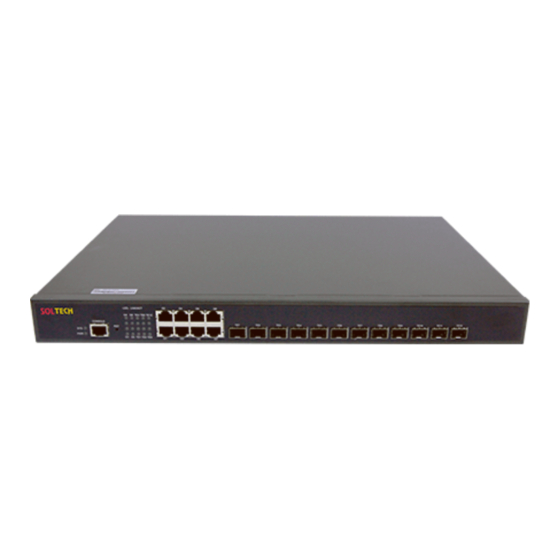
The section describes the characteristics and parameters of SFC4200A and gives an overview of SFC4200A. 1.1 Appearance Description for Standard Configuration The built-in ports of SFC4200A are: 8 gigabit Ethernet RJ45 ports, 12 10G SFP+ ports, 1 Console port. See table 1-1. Table 1-1 Attributes of the built-in port... -
Page 5: Sfc4200A Systematic Characteristic Parameters
8 Gigabit TX ports 8 Gigabit TX ports SFP+ 10G SFP+ ports 12 10G SFP+ ports Figure 1-2 Back template of the SFC4200A switch Table 1-3 Parts at the back template of the SFC4200A sw itch Abbrev. Name Description AC power socket AC100~240V. - Page 6 SFC4200A Hardware Installation RFC 1157 SNMP v1/v2 Network RFC 1213 MIB II management standard RFC 1757 RMON 1,2,3,9 Flash Memory: 16M Bytes Memory SDRAM: 512MBytes; Standard 8 10/100/1000BASE-T ports configuration 12 10G SFP+ ports 1 Console port Dimensions mm 442.50×315×44 (W×D×H)
-
Page 7: Rohs Description
SFC4200A Hardware Installation 1.3 ROHS Description - 4 -... -
Page 8: Chapter 2 Installation Preparation
Similar to other electronic products, the semiconductor chip easily gets damaged if you power on or off abruptly and frequently. To restart up the switch of SFC4200A, you have to open the power on-off after the power is cut down for three to five seconds. -
Page 9: Safety Principles For Live Working
SFC4200A Hardware Installation Read the installation guide carefully before you operate the system. Only professionals are allowed to install or replace the switch. Pull out the AC power socket and close the direct-current power before operating on the machine box or working beside the power source. -
Page 10: Electrostatic Discharge Damage Prevention
SFC4200A Hardware Installation 2.2.4 Electrostatic Discharge Damage Prevention Electrostatic discharge may damage devices and circuits. Improper treatment may caus e the switch to malfunction completely or discontinuously. Move or locate the devices according to the measures of electrostatic discharge preven tion, ensuring the machine box connects the ground. -
Page 11: Power Requirements
2.4 Installation Tools and Device The tools and devices to install the SFC4200A switch are not provided by the SFC4200 A switch. You yourself need to prepare them. The following are the tools and devices ne... -
Page 12: Chapter 3 Installing The Sfc4200A Switch
3.2.1 Installing the Machine Box on the Desk The SFC4200A switch can be directly put on the smooth and safe desk. Note: Do not put things weighing 4.5 kg or over 4.5 kg on the top of the switch. -
Page 13: Installing The Machine Box On The Cabinet
RJ45 plug. After you connect the console port to the serial port of PC through a c onsole cable, you can configure and monitor the switch of SFC4200A by running a ter minal emulation software, such as super Windows terminal. The cable is provided acco rding to the host. - Page 14 The other end of the console cable is DB9, and the RJ45 plug is put into the socket of t he console port on the SFC4200A switch. Figure 3-4 The inner connection of the 1-to-8 RJ45 cable (RLC0301). Figure 3-5 Connecting the console port of SFC4200A and computer Table 3-1 Pins of the console port Name...
-
Page 15: Connecting 10G Ethernet Sfp+ Ports
No connect Note: The console port of SFC4200A does not support traffic control. Therefore, you must set the option data traffic control to none when you configure the switch with the super t erminal. Otherwise, the single-pass problem will arise on the super terminal. -
Page 16: Checking After Installation
Figure 3-7 RJ-45 connector on the console port Because the 8 10/100/1000Base-T ports of SFC4200A support the MDI/MDIX self-iden tification of the cable, SFC4200A can adopt five types of direct-through/cross network c ables when it connects other Ethernet terminals. Figure 3-8 Connecting the 1000Base-TX port and other Ethernet terminals Caution: The switch shown in figure 3-8 does not represent the material SFC42 00A. - Page 17 SFC4200A Hardware Installation Check whether the connected power meets the power requirements of the switch Check whether the grounding line is correctly connected. Check whether the switch is correctly connected to other terminal devices. - 14 -...
-
Page 18: Chapter 4 Maintaining Switch
SFC4200A Hardware Installation Chapter 4 Maintaining Switch Caution: Before opening the machine box, make sure that you have released the static yo u carried and then turn off the power on-off of the switch. Before operating any st ep in Appendix B, read the section “Safety Advice”. -
Page 19: Closing Machine Box
SFC4200A Hardware Installation Caution: The switch shown in the above figure does not represent the material SFC420 When the cover is opened, put it aside. The mainboard of the system appears. Note: After taking off the cover, put it horizontally and avoid it to be crushed or collided. Other wise, the machine box is hard to install. -
Page 20: Chapter 5 Hardware Fault Analysis
9600 bps, eight data bits, no sum check bit , one stop bit and no traffic control. 1. Indicator Description The LED indicator shows that the switch is running. The following table shows the indic ators of the SFC4200A switch and their description: - 17 -... - Page 21 SFC4200A Hardware Installation Abbrev. Name Description When the switch is powered on, Power indicator the indicator is on. When the indicator is always on, the system is being started up. System indicator When the indicator flickers, the system works well.
Need help?
Do you have a question about the SFC4200A and is the answer not in the manual?
Questions and answers