Table of Contents
Advertisement
Quick Links
Advertisement
Table of Contents

Related Manuals for Soltech SFC420GM


Summary of Contents for Soltech SFC420GM
- Page 1 SOLTECH SFC420GM Hardware Installation Manual...
-
Page 2: Table Of Contents
Table of Contents Table of Contents Chapter 1 SOLTECH SFC420GM Introduction..................1 1.1 Appearance Description for Standard Configuration................1 1.2 SOLTECH SFC420GM Systematic Characteristic Parameters............2 Chapter 2 Installation Preparation......................... 4 2.1 Caution of Usage............................4 2.2 Safety Advice.............................4 2.2.1 Safety Principles............................ 4 2.2.2 Safety Notices............................ - Page 3 Table of Contents 3.3.3 Connecting Gigabit TX Ports..................... 11 3.4 Checking after Installation......................13 Chapter 4 Maintaining Switch........................14 4.1 Opening the Machine Box......................14 4.2 Closing the Machine Box.......................15 Chapter 5 Hardware Fault Analysis......................16 5.1 Fault Separation..........................16 5.1.1 Faults Relative with Power and Cooling System............. 16 5.1.2 Faults Relative with Port, Cable and Connection..............16 5.2 Indicator Description........................
-
Page 4: Chapter 1 Soltech Sfc420Gm Introduction
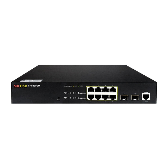
SOLTECH SFC420GM. 1.1 Appearance Description for Standard Configuration The built-in ports of SOLTECH SFC420GM are: 8 gigabit TX ports, 2 GSFP and 1 C LI port. See table 1-1. Table 1- 1 Attributes of the built-in port... -
Page 5: Soltech Sfc420Gm Systematic Characteristic Parameters
It can be used to connect a computer or Console port a terminal for monitoring and configuring the switch. Figure 1- 2 Back template of the SOLTECH SFC420GM switch Table 1- 3 Parts at the back template of the SOLTECH SFC420GM switch Abbrev. Name Description Grounding column The grounding must be fine. - Page 6 SOLTECH SFC420GM Hardware Installation Manual Operating temperature/ 0℃~45℃; 10%~90% non-condensing humidity Storage temperature/ -40℃~70℃; 5%~90% non-condensing humidity Power characteristics input voltage: AC100~240V, input frequency: 50~60Hz Power consumption 7.35W (Max) - 3 -...
-
Page 7: Chapter 2 Installation Preparation
Similar to other electronic products, the semiconductor chip easily gets damaged if you power on or off abruptly and frequently. To restart up the switch of SOLTECH S FC420GM, you have to open the power on-off after the power is cut down for three t o five seconds. -
Page 8: Safety Principles For Live Working
SOLTECH SFC420GM Hardware Installation Manual Read the installation guide carefully before you operate the system. Only professionals are allowed to install or replace the switch. Pull out the AC power socket and close the direct-current power before opera ... -
Page 9: Electrostatic Discharge Damage Prevention
SOLTECH SFC420GM Hardware Installation Manual D. Seek for medical help, or judge the loss and seek for available help. 2.2.4 Electrostatic Discharge Damage Prevention Electrostatic discharge may damage devices and circuits. Improper treatment may cause the switch to malfunction completely or discontinuously. -
Page 10: Power Requirements
4. Installation Tools and Device The tools and devices to install the SOLTECH SFC420GM switch are not provided b y the SOLTECH SFC420GM switch. You yourself need to prepare them. The followi... -
Page 11: Chapter 3 Installing The Soltech Sfc420Gm Switch
Installing the machine box on the desk Installing the machine box on the cabinet 3.2.1 Installing the Machine Box on the Desk The SOLTECH SFC420GM switch can be directly put on the smooth and safe desk. Note: - 8 -... -
Page 12: Installing The Machine Box On The Cabinet
PC through a console cable, you can confi gure and monitor the switch of SOLTECH SFC420GM by running the terminal emul ation software, such as super Windows terminal. The cable is provided according to the host. - Page 13 RJ45 socket, whose pins can be aligned from left to right with the va lue from 1 to 8. Figure 3- 3 RJ-45 connector of the console port Figure 3-4 Connecting the Console port and the PC of the SOLTECH SFC420GM switch Table 3- 1 Pins of the console port Name...
-
Page 14: Connecting Gsfp Ports
SOLTECH SFC420GM Hardware Installation Manual The cable is used to connect the CLI of the SOLTECH SFC420GM switch and the o utside console terminal device. One end of the cable is a 8-pin RJ45 plug and the o ther end is a 9-hole plug (DB9). The RJ45 plug is put into the socket of the CLI on t he SOLTECH SFC420GM switch. - Page 15 SOLTECH SFC420GM Hardware Installation Manual Figure 3-6 RJ-45 connector of the console port Because 8 10/100 Base-T ports of SOLTECH SFC420GM support the MDI/MDIX a uto-identification of the cable, SOLTECH SFC420GM can adopt five classes of dire ct-through/cross network cables when it connects other Ethernet terminals.
-
Page 16: Checking After Installation
SOLTECH SFC420GM Hardware Installation Manual Sending/receiving the paraphase of the data 1 TP1- Sending/receiving the normal phase of data 3 TP3+ Sending/receiving the paraphase of the data 3 TP3- The direct-through or cross network cable has the function of auto-identification, so th e five classes of direct-through/cross network cables can be used to connect other Et hernet devices. -
Page 17: Chapter 4 Maintaining Switch
SOLTECH SFC420GM Hardware Installation Manual Chapter 4 Maintaining Switch Caution: Before opening the machine box, make sure that you have released the static you carried and then turn off the power on-off of the switch. Before operating any step in Appendix B, read the section “Safety Advice”. -
Page 18: Closing The Machine Box
SOLTECH SFC420GM Hardware Installation Manual When the cover is opened, put it aside. The mainboard of the system appears. Note: After taking off the cover, put it horizontally and avoid it to be crushed or collided. Othe rwise, the machine box is hard to install. -
Page 19: Chapter 5 Hardware Fault Analysis
9600 bps, eight data bits, no sum ch eck bit, one stop bit and no traffic control. 1. Indicator Description The following table shows the indicators of the SOLTECH SFC420GM switch and th eir description: - 16 -... - Page 20 SOLTECH SFC420GM Hardware Installation Manual Abbrev. Name Description When the indicator is always on, the system is being started System indicator When the indicator flickers, the system works well. When the switch is powered on, Power indicator the indicator is on.
Need help?
Do you have a question about the SFC420GM and is the answer not in the manual?
Questions and answers