Table of Contents
Advertisement
Quick Links
UF-Series
G
D
ENERAL
ESCRIPTION
The UF20 buffer module is a supplementary device for
regulated DC 24V power supplies, which can be used for
various purposes:
- Deliver DC-power to bridge failures of the DC
voltage supply system.
- Extend the hold-up time after loss of the AC power.
- Deliver extra short-term peak current above the
current rating of the power supply.
It utilizes service-free electrolytic capacitors for storing
the energy which allows usage even at ambient
temperatures up to +70°C.
The buffer module does not require any control wiring.
It can be added in parallel to the load circuit at any
given point.
Buffer modules can be connected in parallel to increase
the output ampacity or the hold-up time.
O
N
RDER
UMBERS
Buffer Module UF20.241
Accessory
ZM1.WALL Panel/ wall-mount bracket
ZM14.SIDE
Oct. 2016 / Rev. 2.0 DS-UF20.241-EN
All parameters are specified at 24V, 20A, 25°C ambient and after a 5 minutes run-in time unless otherwise noted.
Side-mount bracket
www.pulspower.com Phone +49 89 9278 0
24V, 20A, 200
B
M
UFFER
ODULE
Buffering with electrolytic capacitors instead of lead
acid batteries
Buffering of 24V loads
Minimum hold-up time 0.2s at 20A, longer hold-up time
at lower loads
Clear status indication by status LED and signaling
terminals
Quick-connect spring-clamp terminals
3 Years warranty
S
-
D
HORT
FORM
Supply voltage
Required voltage to
charge capacitors
Threshold voltage
for buffer mode
Buffer voltage
Buffer current
Charging time
Current consumption Typ. 80mA
Power dissipation
Buffer time
Temperature range
Dimensions
Weight
M
ARKINGS
IND. CONT. EQ.
UL 508
Germany
UF20.241
, B
M
MS
UFFER
ODULE
ATA
DC 24V
-20%/+25%
19.2-30Vdc
23Vdc
22.5V / V
-1V
Selectable
IN
22.5V / V
-1V
Selectable
IN
20A
Typ. 18s
Stand-by mode
Max. 600mA
During charging
1.9W
Stand-by mode
Min. 200ms
At 22.5V, 20A
Min. 430ms
At 22.5V, 10A
Typ. 310ms
At 22.5V, 20A
Typ. 670ms
At 22.5V, 10A
Typ. 43s
At 22.5V, 0.1A
-25°C to +70°C Operational
64x124x102mm WxHxD
740g / 1.63lb
UL 60950-1
EMC
1/18
Advertisement
Table of Contents

Related Manuals for Puls DIMENSION UF Series


Summary of Contents for Puls DIMENSION UF Series
- Page 1 UF20.241 24V, 20A, 200 UF-Series UFFER ODULE UFFER ODULE Buffering with electrolytic capacitors instead of lead acid batteries Buffering of 24V loads Minimum hold-up time 0.2s at 20A, longer hold-up time at lower loads Clear status indication by status LED and signaling terminals Quick-connect spring-clamp terminals 3 Years warranty...
-
Page 2: Table Of Contents
(available under www.pulspower.com). No part of this document may be reproduced or utilized in any form without our prior permission in writing. Some parts of this unit are patent by PULS (US patent No 091662,063, Des. 424,529, …). ERMINOLOGY AND... -
Page 3: Intended Use
UF20.241 24V, 20A, 200 UF-Series UFFER ODULE 1. I NTENDED This device is designed for installation in an enclosure. Use an appropriate enclosure which protects against mechanical, electrical and fire hazards. This device is intended for professional use in areas such as in industrial control, office, communication, and instrumentation equipment. -
Page 4: Functional Description
UF20.241 24V, 20A, 200 UF-Series UFFER ODULE 3. F UNCTIONAL ESCRIPTION Working principle Charge Storage When the power supply provides sufficient voltage, the buffer module stores energy in the integrated electrolytic capacitors. In case of a voltage dip or loss, this energy is Discharge released to the DC bus in a regulated process. -
Page 5: Electrical Ratings
UF20.241 24V, 20A, 200 UF-Series UFFER ODULE 4. E LECTRICAL ATINGS -20%/+25% Supply voltage Nom. DC 24V Supply voltage range Nom. 19.2 - 30Vdc Normal operating voltage range Typ. 23 – 30Vdc Transfer voltage for switching Typ. 22.5Vdc Back-up threshold jumper set to “22.5V fixed” into buffer mode Typ. -
Page 6: Selection Of The Back-Up Threshold Voltage
UF20.241 24V, 20A, 200 UF-Series UFFER ODULE 5. S ELECTION OF THE HRESHOLD OLTAGE The buffer behavior can be selected with the back-up jumper selector between “Fixed Mode” and “Variable Mode”. Fixed Mode: (Jumper in position „2-3“ or „22.5V fixed”) If the supply output voltage falls below 22.5V, buffering starts and the supply voltage will be kept at this level. -
Page 7: Charging Time
UF20.241 24V, 20A, 200 UF-Series UFFER ODULE 7. C HARGING Charging of the internal capacitors is indicated by the status LED, which is flashing with a slow frequency (1.25Hz). Charging time Min. Initial charging Max. Initial charging Min. Re-charging Max. Re-charging 1) Initial charging is the first charge after voltage is applied to the buffer module. -
Page 8: Active Signal
UF20.241 24V, 20A, 200 UF-Series UFFER ODULE 9. A CTIVE IGNAL The signal “Active” (pin 7) is an opto-coupler output which is low ohmic while buffer capacitors are discharged. Wiring scheme see Fig. 8-2, Fig. 25-1 and Fig. 25-2. Signal voltage Max. -
Page 9: Efficiency And Power Losses
UF20.241 24V, 20A, 200 UF-Series UFFER ODULE 12. E FFICIENCY AND OWER OSSES Efficiency Typ. >99% Power supply mode, 20A output current, capacitors fully charged Power losses Typ. 1.9W Power supply mode, 0A output current, capacitors fully charged 13. L MTBF IFETIME XPECTANCY AND... -
Page 10: Functional Diagram
UF20.241 24V, 20A, 200 UF-Series UFFER ODULE 14. F UNCTIONAL IAGRAM Fig. 14-1 Functional diagram Status Buffer Capacitor Charger & Inrush Limiter Buffer Safety and Reverse- Capacitor Over- Supply Polarity Shut-Down Buffer Capacitor Voltage Voltage Protection Discharger Protection Buffer Capacitor 6 (+) 9 Inhibit Chassis... -
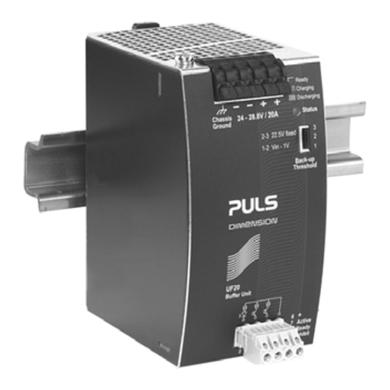
Page 11: Front Side And User Elements
UF20.241 24V, 20A, 200 UF-Series UFFER ODULE 16. F RONT IDE AND LEMENTS Fig. 16-1 Front side A Supply Voltage Terminals Quick-connect spring-clamp terminals, two per polarity + Positive supply voltage terminal – Negative (return) supply voltage terminal B Chassis Ground Terminal Quick-connect spring-clamp terminals Connection of the chassis to ground (earth) is optional and only required for a view specific applications. -
Page 12: 17. Emc
UF20.241 24V, 20A, 200 UF-Series UFFER ODULE 17. EMC The buffer module is suitable for applications in industrial environment as well as in residential, commercial and light industry environment. According to generic standards: EN 61000-6-1 and EN 61000-6-2 EMC Immunity for all operating modes Electrostatic discharge EN 61000-4-2... -
Page 13: Environment
UF20.241 24V, 20A, 200 UF-Series UFFER ODULE 18. E NVIRONMENT Operational temperature -25°C to +70°C (-13°F to 158°F) Storage temperature -40 to +70°C (-40°F to 158°F) For storage and transportation Humidity 5 to 95% r.H. IEC 60068-2-30 Vibration sinusoidal 2-17.8Hz: ±1.6mm; 17.8-500Hz: 2g IEC 60068-2-6 2 hours / axis Vibration random... -
Page 14: Dielectric Strength
UF20.241 24V, 20A, 200 UF-Series UFFER ODULE 21. D IELECTRIC TRENGTH The signal port (active and ready signal and inhibit input) is floating and separated from the supply voltage. Type and factory tests are conducted by the manufacturer. Field tests may be conducted in the field using the appropriate test equipment which applies the voltage with a slow ramp (2s up and 2s down). -
Page 15: Physical Dimensions And Weight
UF20.241 24V, 20A, 200 UF-Series UFFER ODULE 23. P HYSICAL IMENSIONS AND EIGHT Width 64mm 2.13’’ Height 124mm 4.88’’ Depth 102mm 4.02’’ The DIN-rail height must be added to the unit depth to calculate the total required installation depth. Weight 740g / 1.63lb DIN-rail Use 35mm DIN-rails according to EN 60715 or EN 50022 with a height of 7.5 or 15mm. -
Page 16: Accessories
UF20.241 24V, 20A, 200 UF-Series UFFER ODULE 24. A CCESSORIES 24.1. ZM1.WALL - W ALL MOUNTING BRACKET This bracket is used to mount the buffer module on a wall without utilizing a DIN-Rail. The two aluminum brackets and the black plastic slider of the unit have to be detached, so that the steel brackets can be mounted. -
Page 17: Zm14.Side - Side Mounting Bracket
UF20.241 24V, 20A, 200 UF-Series UFFER ODULE 24.2. ZM14.SIDE - S OUNTING RACKET This bracket is used to mount the buffer module sideways with or without utilizing a DIN-Rail. The two aluminum brackets and the black plastic slider of the unit have to be detached, so that the steel brackets can be mounted. -
Page 18: Wiring Diagrams
UF20.241 24V, 20A, 200 UF-Series UFFER ODULE 25. W IRING IAGRAMS Fig. 25-1 General wiring diagram Fig. 25-2 Signals supplied from an external voltage source Status Status DC-OK DC-OK Load Overload UF20 Overload UF20 Load Back-up Back-up Buffer Buffer Threshold Threshold Module Module...
Need help?
Do you have a question about the DIMENSION UF Series and is the answer not in the manual?
Questions and answers