Puls DIMENSION U Series Manual
Hide thumbs
Also See for DIMENSION U Series:
- Instructions manual (12 pages) ,
- Manual (11 pages) ,
- Quick start manual (9 pages)
Table of Contents
Advertisement
Quick Links
–
U Series
1. G
D
ENERAL
ESCRIPTION
Power failures or voltage fluctuations can cause
damage and downtime, which usually costs a lot of
time and money. The UB10.241 together with a
battery module offers a reliable and economical
protection for 24V applications.
The output is isolated from the input, which allows
an easy separation of buffered and non-buffered
branches. The energy of the battery will not be
wasted by uncritical consumers.
In times when the power supply provides sufficient
voltage, the DC-UPS charges the 12V battery. In
case the input power fails, the battery voltage will
be boosted to a 24V level and the energy will be
released in a regulated process to the load.
The included battery management incorporates a
battery charger, a deep-discharge protection and
an overload protection to achieve a long service life
of the battery.
The availiability of the DC-UPS is reported by lamps
and relay contacts. The DC-UPS automatically
checks the installation, the battery fuse and the
quality and presence of the battery. Diagnosis is
very easy, thanks to clear understandable indicators
and relay contacts for remote signaling.
Extensive protection features protect the unit
against wrong battery polarity, wrong battery
voltage, wrong input oltage or output overloads.
3. O
N
RDER
UMBERS
DC-UPS
UB10.241
Accessory
UZK12.07
ZM1.WALL
March 2006 DS-UB10.241-ENRev 2.0 / All parameters are specified at 24V, 10A and 25°C ambient unless otherwise noted.
24V, 10A
12V, 7Ah Battery module
Wall mounting bracket
www.pulspower.com Phone +49 89 9278 0
DC-UPS
■
Requires only one 12V battery
■
Regulated output voltage in buffer mode
■
Compact, width only 49mm
■
50% power reserves
■
Low voltage drop between input and output
■
Electronically protected against output overloads
■
Extensive battery management including battery
quality and installation tests
■
Soft charger for optimum battery life
■
Extensive diagnostic and monitoring functions
■
Selectable buffer time limiter
■
3 Year warranty
2. S
-
HORT
FORM
Operating voltage
DC 24V
Voltage range
22.5-30Vdc
Output voltage
22.4V
Voltage drop
< 0.3V at 10A
IN/OUT
Output current
0 to 15A
0 to 10A, cont.
0 to 15A, for 5s Buffer mode
Input current
typ. 0.12A
max. 1.1A
*)
add output current to calculate the total input current
Charging current
typ. 1.5A
Charging time
typ. 5h
Cut-in threshold
typ. 22.5V
Power losses
2.7W
4.6W
Buffer time
min. 6' 15''
typ. 8' 30''
typ. 32'
Allowed batteries
>3.9Ah,
< 27Ah
Temperature range
-25°C...+60°C
Derating
0.25A/°C
Dimensions
49x124x117mm WxHxD
Weight
530g
4. M
ARKINGS
pending
Germany
UB10.241
24V, 10A
D
ATA
2%
±
Buffer mode
Normal mode
Normal mode
Buffer mode
*)
Standby mode
*)
Charging mode
into 12V battery
12V, 7Ah battery
Standby mode
10A, Normal mode
at 10A, 7Ah battery
at 10A, 7Ah battery
at 4A, 7Ah battery
VRLA batteries
operational
+60 to +70°C
pending
EMC, LVD
1/11
Advertisement
Table of Contents

Related Manuals for Puls DIMENSION U Series


Summary of Contents for Puls DIMENSION U Series
-
Page 1: General Description
UB10.241 – U Series 24V, 10A DC-UPS ■ Requires only one 12V battery ■ Regulated output voltage in buffer mode ■ Compact, width only 49mm ■ 50% power reserves ■ Low voltage drop between input and output ■ Electronically protected against output overloads ■... -
Page 2: Table Of Contents
UB10.241 – U Series 24V, 10A NDEX NDEX 1. General Description ........1 12. Relay Contacts and Inhibit Input ....6 2. Short-form Data .......... 1 13. Terminals and Wiring ......... 7 3. Order Numbers..........1 14. Reliability............. 8 4. Markings ............1 15. -
Page 3: Functional Diagram
UB10.241 – U Series 24V, 10A 5. F UNCTIONAL IAGRAM Fig. 5-1 Functional diagram DC- UPS Input / Electronic Buffered Power Output Current Input Output Load Supply Isolator Limiter Inhibit + Inhibit - Battery Boost Controller Status LED (green) Charger Converter Diagnosis LED (yellow) -
Page 4: Required Settings Before Use
UB10.241 – U Series 24V, 10A 7. R EQUIRED ETTINGS BEFORE Setting the buffering timer: The unit is equipped with a buffering timer, which limits the max. buffer time to save battery capacity. The rotary switch on the front allows the setting of a timer to the following 6 steps: - Indefinite timer deactivated, buffering until the deep discharge protection stops the buffer mode. -
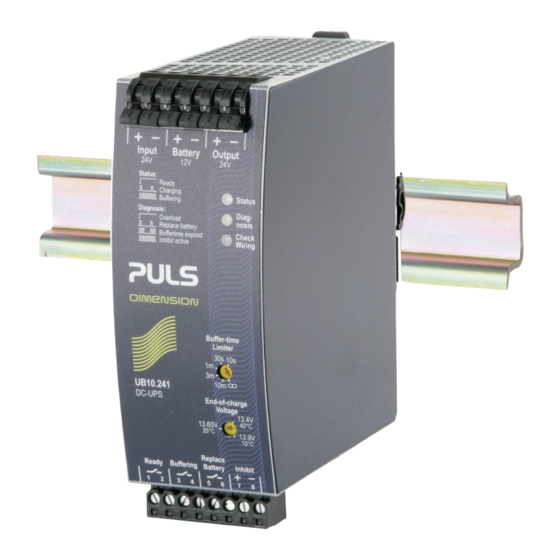
Page 5: Front Side And User Elements
UB10.241 – U Series 24V, 10A 9. F RONT IDE AND LEMENTS Power Port The green LED shows the status of the DC-UPS Quick-connect spring-clamp Ready: Battery is charged > 85%, no wiring failure is recognized, terminals. Connections for: input voltage is sufficient and inhibit signal is not active. Input voltage Charging: Battery is charging, battery capacity is below 85% Battery and... -
Page 6: Battery Quality Test
LED on the front of the unit. Once the battery quality test indicates a bad quality of the battery, it is recommended to change the battery as soon as possible A replacement for the battery can be ordered from PULS under UZB12.07. 11. C HECK IRING The wiring between the battery and the DC-UPS will be checked periodically. -
Page 7: Terminals And Wiring
UB10.241 – U Series 24V, 10A 13. T ERMINALS AND IRING Power terminals Type Bi-stable, quick-connect spring clamp terminals. IP20 Finger safe construction. Suitable for field- and factory installation. Shipped in open position. Solid wire 0.5-6mm Stranded wire 0.5-4mm 20-10AWG Ferrules Allowed, but not required Pull-out force... -
Page 8: Reliability
UB10.241 – U Series 24V, 10A 14. R ELIABILITY Lifetime expectancy min. T.b.d. 40°C, normal mode min. T.b.d. 25°C, normal mode MTBF SN 29500, IEC 61709 T.b.d. 40°C, normal mode T.b.d. 25°C, normal mode T.b.d. 40°C, buffer mode T.b.d. 25°C, buffer mode MTBF MIL HDBK 217F T.b.d. -
Page 9: Environment
UB10.241 – U Series 24V, 10A 16. E NVIRONMENT Operational temperature -25°C to +70°C full power, for the DC-UPS control unit, keep battery in a cold environment! Derating 0,25A/°C +60°C…+70°C, buffer mode see Fig. 16-2 0,43A/°C +60°C…+70°C, normal mode see Fig. -
Page 10: Safety
UB10.241 – U Series 24V, 10A 18. S AFETY Output voltage SELV IEC/EN 60950-1 PELV EN 60204-1, EN 50178, IEC 60364-4-41 Class of protection Isolation resistance > 5MOhm Power port to housing, 500Vdc PE resistance < 0.1Ohm between housing and chassis ground terminal Dielectric strength 500Vac Power port to signal port... -
Page 11: Physical Dimensions And Weight
UB10.241 – U Series 24V, 10A 21. P HYSICAL IMENSIONS AND EIGHT Width 49mm / 1.93’’ Height 124mm / 4.88’’ plus height of signal connector Depth 117mm / 4.61’’ plus depth of DIN-rail Weight 530g / 1.17lb DIN-Rail Use DIN-rails according to EN 60715 or EN 50022 with a height of 7.5 or 15mm Fig.
Need help?
Do you have a question about the DIMENSION U Series and is the answer not in the manual?
Questions and answers