Advertisement
Table of Contents
- 1 Intended Use
- 2 Installation Instructions
- 3 Typical Wiring Scheme
- 4 Control and Monitoring Features
- 5 Reset Input
- 6 Efficiency and Power Losses
- 7 Functional Diagram
- 8 Front Side and User Elements
- 9 Terminals and Wiring
- 10 Lifetime Expectancy
- 11 Regulatory Compliance
- 12 Physical Dimensions and Weight
- Download this manual
GENERAL DESCRIPTION
The
PISA-B
devices
eight channel protection modules with integrated
electronic fuses for 24V systems. They distribute the
current of a large power source to eight output
channels each of lower current and therefore allowing
for smaller wires to be used.
The output current of each channel can be set
individually. Channel 1 and 2 are optimized for loads
with large input capacitances. Connect such loads to
these channels to avoid false tripping or unexpected
switch-off such loads.
The PISA-B-812-B1 is equipped with a common
tripping signaling relay contact that reports tripped
channels, while the PISA-B-812-B4 has a digital coded
signal output built in for this function.
All PISA-B devices are equipped with push-in
terminals, which are optimized for automated wiring.
The mechanically robust housing is made of a high-
grade, reinforced molded material on the front and
of an aluminum body, which permits surrounding
temperatures up to +70°C.
ORDER NUMBERS
Description:
Electronic Fuse PISA-B-812-Bx-xx
Order Number:
PISA-B-812-B1 Common signaling relay contact
PISA-B-812-B4 Digital coded signal output
Accessories:
BUS-BAR1-L102: A set for 2 modules
BUS-BAR1-L155: A set for 3 modules
BUS-BAR1-L500: Single piece L=500mm
All parameters are specified at 24Vdc input voltage, 8x5A output currents, 25°C ambient and after a 5 minutes run-in time unless otherwise noted.
Apr. 2021 / Rev. 0.1 DS-PISA-B-812-Bx-xx-EN
are
DIN
rail
mountable
ELECTRONIC FUSE
8X 24V, 2X 1-12A, 6X 1-10A
• Eight Current Controlled Outputs
• Adjustable Output Currents for Each Channel
• Selective Tripping of Overloaded Channels
• Compatible even with large Capacitive Loads
• Output Currents Displayed Live on LED Matrix
• Remote Reset or Reset via Pushbuttons
• Common Signaling Relay Contact for Tripped
Channels (PISA-B-812-B1)
• Digital Coded Signal Output for Tripped Channels
(PISA-B-812-B4)
• Parameter Settings can be Locked by PIN-Code
• ON/OFF Feature for Each Individual Output
• Easy Wiring - Distribution Terminals for Negative Pole
• 3 Year Warranty
SHORT-FORM DATA
Input voltage
Required input voltage
for turning-on of outputs
Input current
Internal consumption
Nominal output current
Sum current all channels
Current limitation
CH1-CH2
CH3-CH8
Tripping characteristics
Tripping delay
CH1-CH2
CH3-CH8
CH1-CH8
CH1-CH8
Max load capacitance capability
CH1-CH2
CH3-CH8
Voltage drop per channel
CH1-CH2
CH3-CH8
Standby losses
Power losses
Temperature range
Size (w x h x d)
Weight
MAIN APPROVALS
For details and a complete approval list, see chapter 20.
UL 2367
www.pulspower.com
PISA-B-812-B1
PISA-B-812-B4
DC 24V
-20%/+25%
19.6Vdc
40A
40mA
PISA-B-812-B1
35mA
PISA-B-812-B4
Adjustable
1/2/3/4/6/8/10/12A CH1 and CH2
1/2/3/4/6/8/10A
CH3 to CH8
40A
Below +60°C ambient
30A
At +70°C ambient
Derate between +60°C and +70°C
200%
For 1A setting
150%
For 2 - 8A settings
130%
For 10 - 12A settings
50A
Slow or Fast
Selectable
2ms – 2s
At short circuit
<10ms
At short circuit
1.1s
For slow tripping at 1.5x
nominal current
0.22s
For fast tripping at 1.5x
nominal current
100mF
Per channel
20mF
Per channel
125mV
For 10A load
165mV
For 10A load
1W
10.8W
At 8x 5A load
-25°C to 70°C
52x124x130mm
Without DIN rail
370g / 0.82lb
UL 61010-2-201
IEC 61010
IEC 62368 planned
1 / 20
Advertisement
Table of Contents

Related Manuals for Puls PISA-B-812-B1


Summary of Contents for Puls PISA-B-812-B1
- Page 1 Current limitation switch-off such loads. CH1-CH2 200% For 1A setting The PISA-B-812-B1 is equipped with a common 150% For 2 - 8A settings tripping signaling relay contact that reports tripped 130% For 10 - 12A settings...
- Page 2 Control and Monitoring Features..... 19 Safety Features and Protection Features..17 Digital Coded Interface (PISA-B-812-B4)... 11 20 Approvals and Fulfilled Standards....18 Alarm Relay Contact (PISA-B-812-B1)....11 21 Regulatory Compliance........18 10 Reset Input............11 22 Physical Dimensions And Weight...... 19 11 Efficiency and Power Losses......
-
Page 3: Intended Use
PISA-B-812-B1 PISA-B-812-B4 Intended Use This device is designed for installation in an enclosure and is intended for commercial use, such as in industrial control, process control, monitoring and measurement equipment or the like. Do not use this device in equipment, where malfunctioning may cause severe personal injury or threaten human life without additional appropriate safety devices, that are suited for the end-application. -
Page 4: Typical Wiring Scheme
PISA-B-812-B1 PISA-B-812-B4 Typical Wiring Scheme One fuse module is suitable to distribute the current to 8 consumers. If there are more than eight consumers, up to eight fuse modules can be used (64 consumers). The supply of the individual fuse modules can be done by means of power-bus- bars, which are available as accessory parts. - Page 5 Internal current Stand-by current with no load current on the outputs consumption typ. 40mA For PISA-B-812-B1 typ. 35mA For PISA-B-812-B4 Output The output can supply any kind of loads, including inductive and capacitive loads. The maximum size of capacitive loads is specified in the table below (see Tab.
- Page 6 PISA-B-812-B1 PISA-B-812-B4 Output voltage nom. DC 24V The output voltage is equal to the input voltage minus the voltage drop of the module. Voltage drop per channel typ. 125mV For CH1 or CH2 at 10A load when all other channels are not loaded typ.
- Page 7 PISA-B-812-B1 PISA-B-812-B4 Output Tripping Characterstics The tripping current can be set individually for all channels and the tripping characteristic can be set to Slow or Fast as a common parameter for all channels. Tripping characteristic Slow / Fast selectable, factory setting is Fast Tripping delay typ.
-
Page 8: Control And Monitoring Features
PISA-B-812-B1 PISA-B-812-B4 Control And Monitoring Features The LED matrix display provides information about measurement, set parameters and errors and contains two modes. To switch between the two modes, the measurement mode and the parameter mode, push the SET button and the channel control button 4. - Page 9 PISA-B-812-B1 PISA-B-812-B4 Parameter Mode The “A” scale on the right side of the LED Matrix is used in this mode, which is also indicated by the triangular LED below the LED matrix display. In this mode the set values for the tripping currents for each individual channel are displayed and the LED matrix display also shows if a channel has switched off due to a too high current or on purpose.
- Page 10 PISA-B-812-B1 PISA-B-812-B4 LED pattern example Fig. 7-2: LED Light pattern in measurement mode Fig. 7-3: LED Light pattern in parameter mode Description: Description: Channel 1 is loaded with 40-60% of the set current Channel 1 is set to 12A but turned off with push-button...
-
Page 11: Reset Input
1900ms. Fig. 8-1: Digital Coded Alarm Signal – Signal Sequence Alarm Relay Contact (PISA-B-812-B1) The device is equipped with an alarm contact. The normally closed (NC) contact closes as soon as one output channel has switched off (common signalling) or the input voltage is lower than 19Vdc. -
Page 12: Functional Diagram
PISA-B-812-B1 PISA-B-812-B4 12. Functional Diagram Fig. 12-1: Functional diagram PISA-B-812-B1 Fig. 12-2: Functional diagram PISA-B-812-B4 All parameters are specified at 24Vdc input voltage, 8x5A output currents, 25°C ambient and after a 5 minutes run-in time unless otherwise noted. Apr. 2021 / Rev. 0.1 DS-PISA-B-812-Bx-xx-EN www.pulspower.com... -
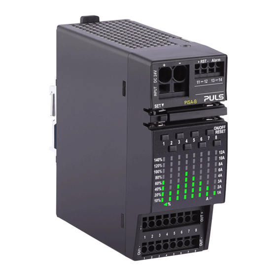
Page 13: Front Side And User Elements
Positive input pole (−) Negative (return) input pole Alarm signal (pin 13-14) PISA-B-812-B1: Relay contact PISA-B-812-B4: Digital coded signal Signal input to restart switched-off channels (pin 11-12) Slot for interconnecting power-bus-bar for supply voltage E1: Interconnection for positive input power-bus-bar... -
Page 14: Lifetime Expectancy
PISA-B-812-B1 PISA-B-812-B4 15. Lifetime Expectancy The Lifetime expectancy shown in the table indicates the minimum operating hours (service life) and is determined by the lifetime expectancy of the built-in electrolytic capacitors. Lifetime expectancy is specified in operational hours and is calculated according to the capacitor’s manufacturer specification. - Page 15 PISA-B-812-B1 PISA-B-812-B4 17. EMC The EMC behavior of the device is designed for applications in industrial environment as well as in residential, commercial and light industry environment without any restrictions. The device complies with EN 61000-6-1, EN 61000-6-2, EN 61000-6-3, EN 61000-6-4.
- Page 16 PISA-B-812-B1 PISA-B-812-B4 18. Environment Operational temperature -25°C to +70°C (-13°F to 158°F) The operational temperature is the ambient or surrounding temperature and is defined as the air temperature 2cm below the device. Storage temperature -40°C to +85°C (-40°F to 185°F)
- Page 17 PISA-B-812-B1 PISA-B-812-B4 19. Safety Features And Protection Features Isolation resistance >10MOhm At delivered condition between power port and signals, measured with 500Vdc >10MOhm At delivered condition between power port and housing, measured with 500Vdc >10MOhm At delivered condition between signals and housing,...
-
Page 18: Regulatory Compliance
PISA-B-812-B1 PISA-B-812-B4 20. Approvals And Fulfilled Standards IEC 61010 CB Scheme Certificate IEC 61010-2-201 - Electrical Equipment for Measurement, Control and Laboratory Use - Particular requirements for control equipment IEC 62368 CB Scheme Certificate planned IEC 62368-1 - Audio/video, information and communication... -
Page 19: Physical Dimensions And Weight
PISA-B-812-B1 PISA-B-812-B4 22. Physical Dimensions And Weight Width 52mm / 2.05'' Height 124mm / 4.88'' Depth 130mm / 5.12'' The DIN rail height must be added to the unit depth to calculate the total required installation depth. Weight 370g / 0.82lb DIN rail Use 35mm DIN rails according to EN 60715 or EN 50022 with a height of 7.5 or 15mm. - Page 20 PISA-B-812-B1 PISA-B-812-B4 23. Accessories 23.1. POWER CONNECTION - POWER-BUS-BARS These power-bus-bars are used to connect several PISA-B modules electrically together. The power-bus-bars distribute the 24V supply voltage of the PISA-B modules. The length of 102mm is suitable to connect two PISA-B modules together. The length of 155mm is suitable to connect three PISA-B modules together.
Need help?
Do you have a question about the PISA-B-812-B1 and is the answer not in the manual?
Questions and answers