Table of Contents
Advertisement
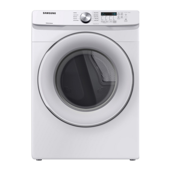
SERVICE
CLOTHES DRYER
DVE45T6005W/AC
CLOTHES DRYER
Basic Model : DV6000R
Project Name : DV6000T
Model Code : DVE45T6005W/AC
DVG45T6005W/AC DVG45T6005W
DVE45T6000W/A3
DVG45T6000W/A3
DVE45T6200W/A3
DVG45T6200W/A3
Manual
1. Safety Instructions
2. Features and Specifications
3. Disassembly and Reassembly
4. Troubleshooting
5. PCB diagram
6. Wiring diagram
7. Reference
DVE45T6005W
DVE45T6000W
DVG45T6000W
DVE45T6200W
DVG45T6200W
CONTENTS
Advertisement
Table of Contents


Need help?
Do you have a question about the DV6000R and is the answer not in the manual?
Questions and answers